2011 NISSAN LATIO diagram
[x] Cancel search: diagramPage 511 of 3787

BL-1
BODY
C
DE
F
G H
J
K L
M
SECTION BL
A
B
BL
N
O P
CONTENTS
BODY, LOCK & SECURITY SYSTEM
SERVICE INFORMATION .. ..........................4
PRECAUTIONS .............................................. .....4
Precaution for Supplemental Restraint System
(SRS) "AIR BAG" and "SEAT BELT PRE-TEN-
SIONER" ............................................................. ......
4
Precaution Necessary for Steering Wheel Rota-
tion After Battery Disconnect ............................... ......
4
Precaution for Procedure without Cowl Top Cover ......5
Precaution for Work ..................................................5
PREPARATION ...................................................6
Special Service Tool ........................................... ......6
Commercial Service Tool ..........................................6
SQUEAK AND RATTLE TROUBLE DIAG-
NOSES ................................................................
7
Work Flow ........................................................... ......7
Generic Squeak and Rattle Troubleshooting ............9
Diagnostic Worksheet .............................................11
HOOD .................................................................13
Fitting Adjustment ............................................... ....13
Removal and Installation .........................................14
Removal and Installation of Hood Lock Control .. ....15
Hood Lock Control Inspection .................................17
RADIATOR CORE SUPPORT ....................... ....19
Removal and Installation .........................................19
FRONT FENDER ................................................21
Removal and Installation .........................................21
POWER DOOR LOCK SYSTEM .................... ....22
Component Parts and Harness Connector Loca-
tion ...................................................................... ....
22
System Description .................................................23
CAN Communication System Description ...............25
Schematic ...............................................................26
Wiring Diagram - D/LOCK - .....................................27
Schematic ...............................................................31
Wiring Diagram - D/LOCK - .....................................32
Terminal and Reference Value for BCM ..................37
Work Flow ............................................................ ....41
CONSULT-III Function (BCM) .................................41
Trouble Diagnosis Symptom Chart ...................... ....43
BCM Power Supply and Ground Circuit Inspection
....
43
Door Switch Check (Hatchback) ..............................44
Door Switch Check (Sedan) ....................................47
Key Switch (Insert) Check .......................................48
Door Lock and Unlock Switch Check ......................49
Front Door Lock Assembly LH (Actuator) Check .....52
Front Door Lock Assembly RH (Actuator) Check ....53
Rear Door Lock Actuator LH/RH Check .............. ....54
Front Door Lock Assembly LH (Key Cylinder
Switch) Check ..........................................................
54
Passenger Select Unlock Relay Circuit Inspection
(With Intelligent Key) ........................................... ....
56
REMOTE KEYLESS ENTRY SYSTEM .............58
Component Parts and Harness Connector Loca-
tion ...........................................................................
58
System Description ..................................................58
CAN Communication System Description ...............60
Schematic ................................................................61
Wiring Diagram - KEYLES - ....................................62
Terminal and Reference Value for BCM ..................65
How to Perform Trouble Diagnosis ...................... ....69
Preliminary Check ...................................................69
CONSULT-III Function (BCM) .................................69
Work Flow ............................................................ ....71
Trouble Diagnosis Symptom Chart ..........................71
Keyfob Battery and Function Check ........................72
ACC Switch Circuit Check .......................................74
Door Switch Check (Hatchback) ..............................74
Door Switch Check (Sedan) ....................................76
Key Switch (Insert) Check .......................................78
Hazard Function Check ...........................................79
Horn Function Check ...............................................79
Interior Lamp and Ignition Keyhole Illumination
Function Check ........................................................
80
Remote Keyless Entry Receiver Check ...................80
Revision: May 2010 2011 Versa
Page 512 of 3787

BL-2
Keyfob Function (Lock) Check ...............................82
Keyfob Function (Unlock) Check ............................82
ID Code Entry Procedure .................................... ...83
Keyfob Battery Replacement ............................... ...85
Removal and Installation of Remote Keyless Entry
Receiver .............................................................. ...
85
INTELLIGENT KEY SYSTEM ............................86
Component Parts and Harness Connector Loca-
tion ....................................................................... ...
86
System Description .................................................88
CAN Communication System Description ..............95
Schematic ............................................................ ...96
Wiring Diagram - I/KEY - ..................................... ...98
Intelligent Key Unit Har ness Connector Terminal
Layout .................................................................. ..
108
Terminal and Reference Value for Intelligent Key
Unit ........................................................................
108
Steering Lock Solenoid Harness Connector Ter-
minal Layout ..........................................................
110
Terminal and Reference Value for Steering Lock
Solenoid .................................................................
110
Terminal and Reference Value for BCM ................111
Trouble Diagnosis Procedure ................................115
CONSULT-III Functions (INTELLIGENT KEY) ......117
CONSULT-III Application Item ............................. ..117
Trouble Diagnosis Symptom Chart ........................119
CAN Communication System Inspection ...............126
Power Supply and Ground Circuit Inspection ........126
Key Switch (Intelligent Key Unit Input) Check .......127
Key Switch (BCM Input) Check .............................128
Ignition Knob Switch Check ................................. ..129
Door Switch Check (Hatchback) ............................131
Door Switch Check (Sedan) ..................................134
Door Request Switch Check ..................................135
Back Door Request Switch Check (Hatchback) ....137
Trunk Opener Request Switch Check (Sedan) ... ..138
Unlock Sensor Check ............................................140
Intelligent Key Warning Buzzer(s) Check ..............142
Outside Key Antenna (Dri ver Side and Passenger
Side) Check ......................................................... ..
143
Outside Key Antenna (Rear Bumper) Check .........144
Inside Key Antenna Check ....................................146
Steering Lock Solenoid Check ............................ ..147
Key Interlock Solenoid (With M/T) Check ..............149
Ignition Switch Position Check ............................ ..150
Stop Lamp Switch Check (With CVT or A/T) ....... ..150
Stop Lamp Switch Check (With M/T) .....................152
CVT or A/T Shift Selector (Park Position Switch)
Check .................................................................. ..
153
"P-SHIFT" Warning Lamp (With CVT or A/T)
Check ....................................................................
154
"LOCK" Warning Lamp (With M/T) Check .............155
"KEY" Warning Lamp (RED) Check ......................155
"KEY" Warning Lamp (G REEN) Check .................155
Check Warning Chime in Combination Meter ........156
Hazard Function Check .........................................156
Horn Function Check .... .........................................157
Headlamp Function Chec k ....................................157
Intelligent Key Battery Re placement .....................158
Remote Keyless Entry Func tion ............................158
Removal and Installation of Intelligent Key Unit ... .158
DOOR ...............................................................160
Fitting Adjustment ................................................ .160
Removal and Installation .......................................163
Back Door Stay Disposal ..................................... .166
FRONT DOOR LOCK .......................................167
Component Parts Location .................................. .167
Removal and Installation .......................................167
REAR DOOR LOCK ....................................... ..170
Component Parts Location .................................. .170
Removal and Installation .......................................170
BACK DOOR LOCK ....................................... ..173
Component Parts and Harness Connector Loca-
tion ....................................................................... .
173
System Description ...............................................173
Wiring Diagram - B/DOOR - ..................................174
Terminal and Reference Value for BCM ...............176
Terminal and Reference Value for Intelligent Key
Unit ....................................................................... .
180
CONSULT-III Function (BCM) ..............................182
Work Flow .............................................................183
Trouble Diagnosis Chart by Symptom ..................183
BCM Power Supply and Ground Circuit Inspection
.
183
Check Back Door Opener Switch Circuit (Without
Intelligent Key or Power Windows) ...................... .
184
Check Back Door Opener Switch Circuit (Without
Intelligent Key, with Power Windows) .................. .
187
Check Back Door Opener Switch Circuit (With In-
telligent Key) ........................................................ .
189
Check Back Door Lock Assembly (Actuator) Cir-
cuit ........................................................................
191
Removal and Installation .......................................193
TRUNK LID ..................................................... ..195
Fitting Adjustment ................................................ .195
Trunk Lid Assembly ..............................................195
Trunk Lid Lock ......................................................196
Trunk Lid Striker ....................................................196
TRUNK LID OPENER .......................................198
Component Parts and Harness Connector Loca-
tion ....................................................................... .
198
System Description ...............................................198
Wiring Diagram - TLID - ........................................199
Terminal and Reference Value for BCM ...............201
Terminal and Reference Value for Intelligent Key
Unit ....................................................................... .
205
CONSULT-III Function (BCM) ..............................207
Work Flow .............................................................208
Trouble Diagnosis Chart by Symptom ..................208
BCM Power Supply and Ground Circuit Inspection
.
208
Revision: May 2010 2011 Versa
Page 513 of 3787

BL-3
C
DE
F
G H
J
K L
M A
B
BL
N
O P
Check Trunk Lid Opener S
witch Circuit (Without
Intelligent Key) .................................................... ..
209
Check Trunk Lid Opener Switch Circuit (With Intel-
ligent Key) ........................................................... ..
212
Check Trunk Release Solenoid Circuit .................214
FUEL FILLER LID OPENER ............................216
Removal and Installation of Fuel Filler Lid Opener ..216
VEHICLE SECURITY (THEFT WARNING)
SYSTEM ...........................................................
217
Component Parts and Harness Connector Loca-
tion ...................................................................... ..
217
System Description ...............................................218
CAN Communication System Description .............220
Schematic .............................................................221
Wiring Diagram - VEHSEC - .................................222
Terminal and Reference Value for BCM ...............226
Terminal and Reference Value for Intelligent Key
Unit ...................................................................... ..
230
CONSULT-III Function (BCM) ...............................232
Trouble Diagnosis .................................................234
Preliminary Check .................................................234
Symptom Chart .....................................................236
Diagnosis Procedure 1 ..........................................237
Diagnosis Procedure 2 ..........................................239
Diagnosis Procedure 3 ..........................................240
Diagnosis Procedure 4 ..........................................240
Diagnosis Procedure 5 ..........................................240
Diagnosis Procedure 6 ..........................................241
Diagnosis Procedure 7 ..........................................241
Diagnosis Procedure 8 ..........................................242
Diagnosis Procedure 9 ........................................ ..244
NATS (Nissan Anti-Theft System) ................246
Component Parts and Harness Connector Loca-
tion .........................................................................
246
System Description ................................................246
System Composition ..............................................247
ECM Re-communicating Function .........................247
Wiring Diagram - NATS - .......................................249
Terminal and Reference Value for BCM ................250
CONSULT-III Function ........................................ ..254
Trouble Diagnosis Procedure ................................255
Trouble Diagnosis ..................................................257
Diagnosis Procedure 1 ..........................................258
Diagnosis Procedure 2 ..........................................260
Diagnosis Procedure 3 ..........................................261
Diagnosis Procedure 4 ..........................................262
Diagnosis Procedure 5 ..........................................263
Diagnosis Procedure 6 ..........................................264
How to Replace NATS Antenna Amp ....................264
BODY REPAIR ................................................265
Body Exterior Paint Color ......................................265
Body Component Parts .........................................267
Corrosion Protection ..............................................272
Body Sealing .........................................................276
Body Construction .................................................282
Body Alignment .....................................................284
Handling Precaution for Plastics ............................301
Precaution in Repairing High Strength Steel .........305
Foam Repair ..........................................................308
Replacement Operation .........................................311
Revision: May 2010 2011 Versa
Page 537 of 3787

POWER DOOR LOCK SYSTEMBL-27
< SERVICE INFORMATION >
C
DE
F
G H
J
K L
M A
B
BL
N
O P
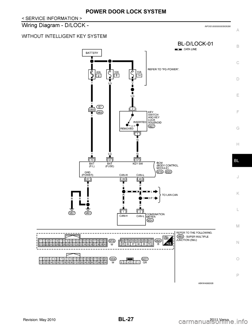
Wiring Diagram - D/LOCK -INFOID:0000000005929286
WITHOUT INTELLIGENT KEY SYSTEM
ABKWA0683GB
Revision: May 2010 2011 Versa
Page 542 of 3787

BL-32
< SERVICE INFORMATION >
POWER DOOR LOCK SYSTEM
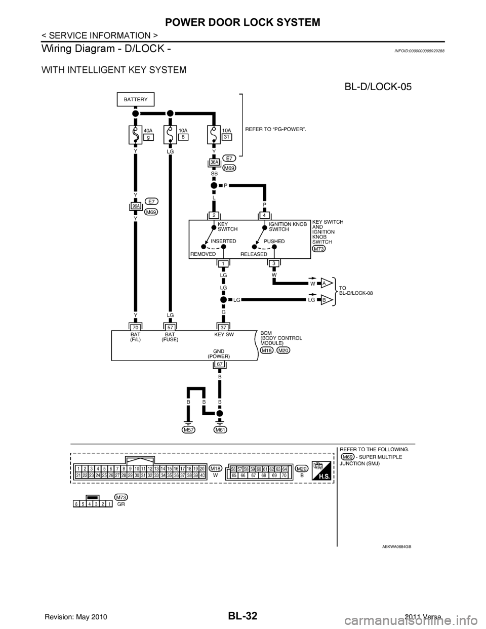
Wiring Diagram - D/LOCK -
INFOID:0000000005929288
WITH INTELLIGENT KEY SYSTEM
ABKWA0684GB
Revision: May 2010 2011 Versa
Page 572 of 3787

BL-62
< SERVICE INFORMATION >
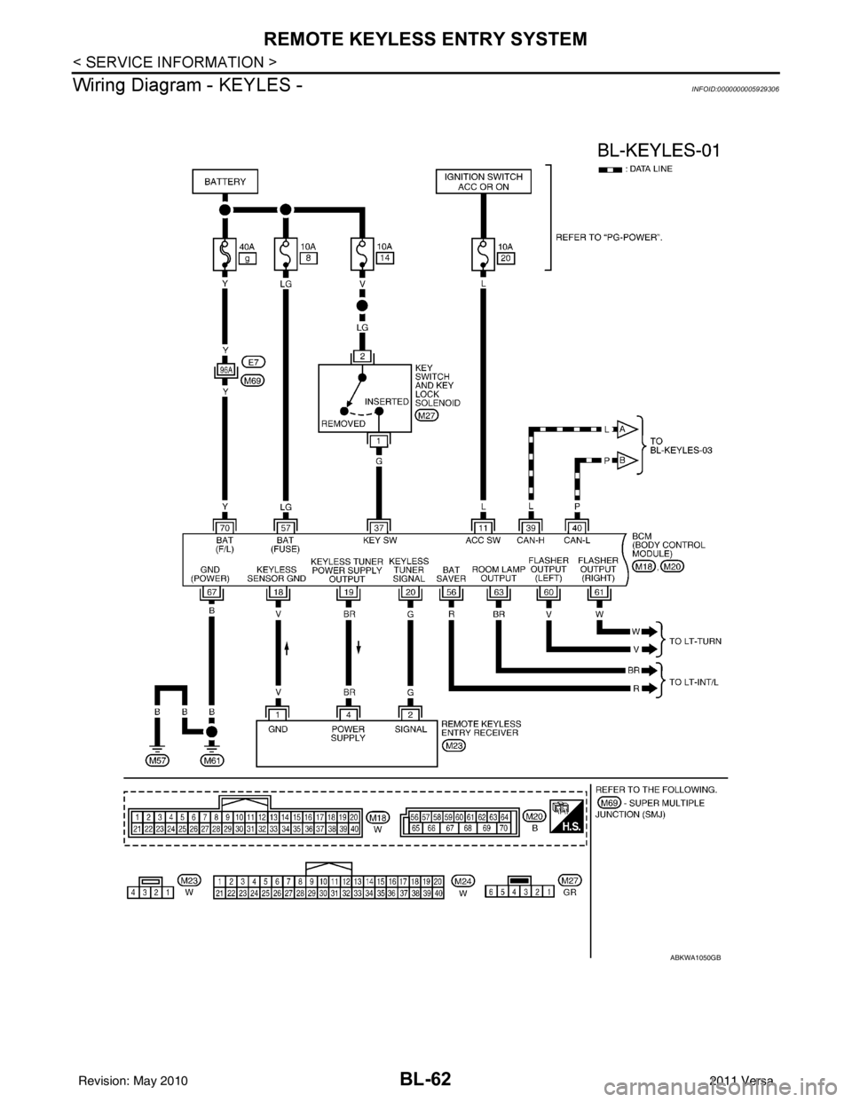
REMOTE KEYLESS ENTRY SYSTEM
Wiring Diagram - KEYLES -
INFOID:0000000005929306
ABKWA1050GB
Revision: May 2010 2011 Versa
Page 598 of 3787

BL-88
< SERVICE INFORMATION >
INTELLIGENT KEY SYSTEM
System Description
INFOID:0000000005929328
• The Intelligent Key system is a system that makes it possible to lock and unlock the door locks (door lock/
unlock function), and start the engine (engine start func tion) by carrying around the Intelligent Key (without
some key operation), which operates based on the results of electronic ID verification using two-way com-
munications between the Intelligent Key and the vehicle (Intelligent Key unit).
• Vehicles equipped with a manual transmission include a key interlock solenoid located in the steering col- umn to prevent accidental shut-off of the ignition sw itch and locking of the steering wheel during driving con-
dition when the vehicle is moving.
CAUTION:
The driver should always carry the Intelligent Key
• Operation of the remote controller buttons on the Inte lligent Key also provides the same functions as the
remote control entry system. (Remote keyless entry functions)
• If an action that does not meet the operating conditions of the Intelligent Key system is taken, the buzzer
goes off to inform the driver. (Warning chime functions)
• When a door lock is locked or unlocked with request switch or remote controller button operation, the hazard
lamps flash and the buzzer (outside vehicle) sounds (Hazard and buzzer reminder function).
• Even if the Intelligent Key battery is completely discharged, the door locks can be locked and unlocked and the engine started with the mechanical key built into the Intelligent Key.
• The settings for each function can be changed with the CONSULT-III.
• If an Intelligent Key is lost, a new Intelligent Key can be registered. A maximum of 4 Intelligent Keys can be registered.
• It has been made possible to diagnose the system and r egister an Intelligent Key with the CONSULT-III.
DOOR LOCK/UNLOCK FUNCTION
Only when pressing the request switch, it is possible to lock and unlock the door by carrying around the Intelli-
gent Key (without some key operation).
System Diagram
10. Steering lock solenoid M6
(bottom view of steering column) 11. Key switch and ignition knob switch M73
(with CVT or A/T) 12. Key switch and ignition knob switch M73
(with M/T)
13. CVT or A/T shift selector (park posi- tion switch) M38
(without M/T) 14. Intelligent key warning buzzer (front
door LH) D6
(view with front door finisher LH re-
moved) 15. Front outside antenna LH D10, RH D106
16. Front door request switch LH D5, RH D103 17. Front door lock assembly LH (door un-
lock sensor) D14 18. Front door switch LH B8, RH B108
19. Rear door switch LH B6, RH B116 20. Front console antenna B125 (view of front console without arm rest
removed)21. Front console antenna B125
(view of front console with arm rest re-
moved)
22. Rear floor antenna B126 (behind rear seat) 23. Trunk opener request switch B129
(sedan) 24. Back door request switch D406
(hatchback)
25. Back door lock assembly (back door switch) D405 (hatchback view
with back door open) 26. Rear bumper antenna B2
(view with rear fascia removed) 27. Intelligent Key warn
ing buzzer (trunk) B32
(sedan)
LIIA2926E
Revision: May 2010 2011 Versa
Page 601 of 3787

INTELLIGENT KEY SYSTEMBL-91
< SERVICE INFORMATION >
C
DE
F
G H
J
K L
M A
B
BL
N
O P
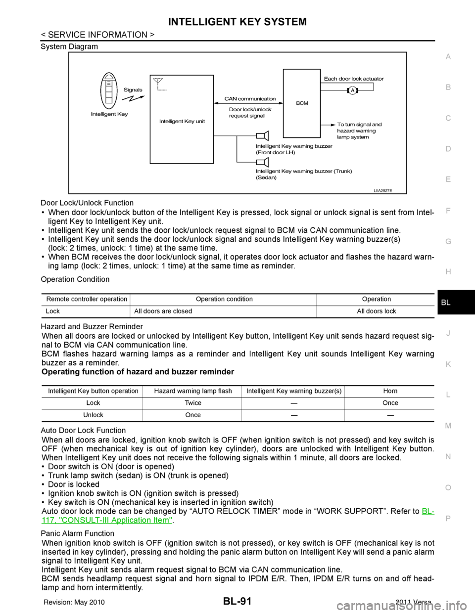
System Diagram
Door Lock/Unlock Function
• When door lock/unlock button of the Intelligent Key is pr
essed, lock signal or unlock signal is sent from Intel-
ligent Key to Intelligent Key unit.
• Intelligent Key unit sends the door lock/unlock request signal to BCM via CAN communication line.
• Intelligent Key unit sends the door lock/unlock signal and sounds Intelligent Key warning buzzer(s) (lock: 2 times, unlock: 1 time) at the same time.
• When BCM receives the door lock/unlock signal, it oper ates door lock actuator and flashes the hazard warn-
ing lamp (lock: 2 times, unlock: 1 time) at the same time as reminder.
Operation Condition
Hazard and Buzzer Reminder
When all doors are locked or unlocked by Intelligent Ke y button, Intelligent Key unit sends hazard request sig-
nal to BCM via CAN communication line.
BCM flashes hazard warning lamps as a reminder and Intelligent Key unit sounds Intelligent Key warning
buzzer as a reminder.
Operating function of hazard and buzzer reminder
Auto Door Lock Function
When all doors are locked, ignition knob switch is OFF (when ignition switch is not pressed) and key switch is
OFF (when mechanical key is out of ignition key cyli nder), doors are unlocked with Intelligent Key button.
When Intelligent Key unit does not receive the following signals within 1 minute, all doors are locked.
• Door switch is ON (door is opened)
• Trunk lamp switch (sedan) is ON (trunk is opened)
• Door is locked
• Ignition knob switch is ON (ignition switch is pressed)
• Key switch is ON (mechanical key is inserted in ignition switch)
Auto door lock mode can be changed by “AUTO RELOCK TIMER” mode in “WORK SUPPORT”. Refer to BL-
117, "CONSULT-III Application Item".
Panic Alarm Function
When ignition knob switch is OFF (ignition switch is not pressed), or key switch is OFF (mechanical key is not
inserted in key cylinder), pressing and holding the panic alarm button on Intelligent Key will send a panic alarm
signal to Intelligent Key unit.
Intelligent Key unit sends alarm request signal to BCM via CAN communication line.
BCM sends headlamp request signal and horn signal to IPDM E/R. Then, IPDM E/R turns on and off head-
lamp and horn intermittently.
LIIA2927E
Remote controller operation Operation condition Operation
Lock All doors are closed All doors lock
Intelligent Key button operation Hazard warning lamp flash Intelligent Key warning buzzer(s) Horn
Lock Twice —Once
Unlock Once ——
Revision: May 2010 2011 Versa