2011 NISSAN LATIO tires
[x] Cancel search: tiresPage 3559 of 3787
RSU-6
< SERVICE INFORMATION >
REAR SUSPENSION ASSEMBLY
REAR SUSPENSION ASSEMBLY
On-Vehicle Inspection and ServiceINFOID:0000000005931084
Make sure the mounting conditions (looseness, backlash) of each component and component conditions
(wear, damage) are within specifications.
SHOCK ABSORBER INSPECTION
Check shock absorber for oil leakage, damage and replace it if necessary.
Wheel AlignmentInspectionINFOID:0000000005931085
DESCRIPTION
Measure wheel alignment under unladen conditions.
NOTE:
“Unladen conditions” means that fuel, engine coolant, and lubricant are full. Spare tire, jack, hand tools and
mats are in designated positions.
PRELIMINARY
Check the following:
1. Tires for improper air pressure and wear.
2. Road wheels for runout. Refer to WT-6
.
3. Wheel bearing axial end play. Refer to RAX-6, "
On-Vehicle Inspection and Service" .
4. Shock absorber operation.
5. Each mounting part of suspension for looseness and deformation.
6. Rear suspension beam for cracks, deformation, and other damage.
7. Vehicle height (posture).
GENERAL INFORMATION AND RECOMMENDATIONS
1. A Four-Wheel Thrust Alignment should be performed. • This type of alignment is recommended for any NISSAN vehicle.
• The four-wheel “thrust” process helps ensure that the vehicle is properly aligned and the steering wheel
is centered.
• The alignment machine itself should be ca pable of accepting any NISSAN vehicle.
• The alignment machine should be checked to ensure that it is level.
2. Make sure the alignment machine is properly calibrated. • Your alignment machine should be regularly calibrated in order to give correct information.
• Check with the manufacturer of your specific al ignment machine for their recommended Service/Cali-
bration Schedule.
THE ALIGNMENT PROCESS
IMPORTANT: Use only the alignment specifications listed in this Service Manual. Refer to RSU-13, "Wheel
Alignment (Unladen*)" .
1. When displaying the alignment settings, many alignment machines use “indicators”: (Green/red, plus or minus, Go/No Go). Do NOT use these indicators.
• The alignment specifications programmed into your alignment machine that operate these indicators may not be correct.
• This may result in an ERROR.
2. Some newer alignment machines are equipped with an optional “Rolling Compensation” method to “com- pensate” the sensors (alignment targets or head units). Do NOT use this “Rolling Compensation”
method.
• Use the “Jacking Compensation” method. After inst alling the alignment targets or head units, raise the
vehicle and rotate the wheels 1/2 turn both ways.
• See Instructions in the alignment machine you are using for more information.
CAMBER INSPECTION
Revision: May 2010 2011 Versa
Page 3560 of 3787
REAR SUSPENSION ASSEMBLYRSU-7
< SERVICE INFORMATION >
C
DF
G H
I
J
K L
M A
B
RSU
N
O P
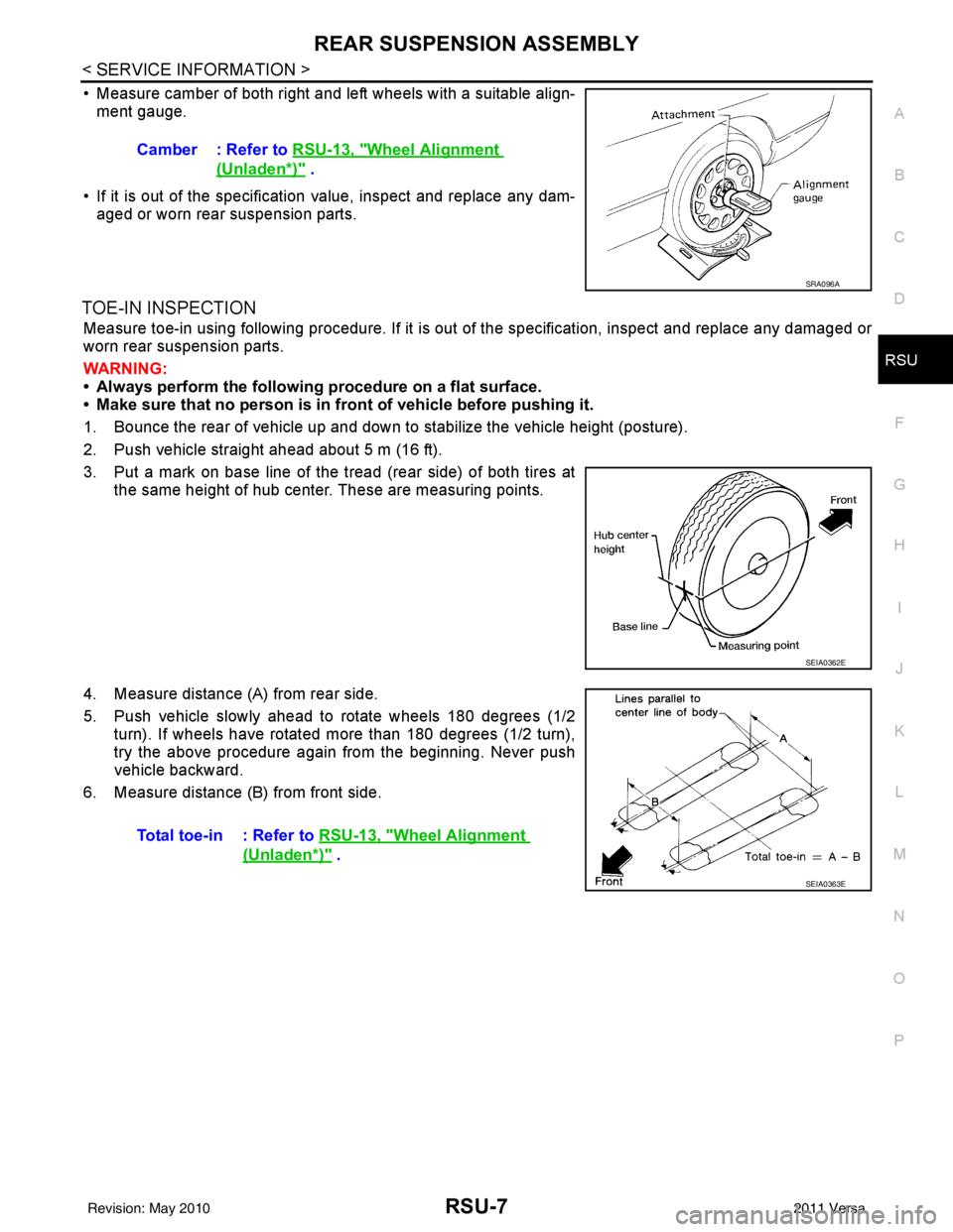
• Measure camber of both right and left wheels with a suitable align- ment gauge.
• If it is out of the specificati on value, inspect and replace any dam-
aged or worn rear suspension parts.
TOE-IN INSPECTION
Measure toe-in using following procedure. If it is out of the specification, inspect and replace any damaged or
worn rear suspension parts.
WARNING:
• Always perform the following procedure on a flat surface.
• Make sure that no person is in fron t of vehicle before pushing it.
1. Bounce the rear of vehicle up and down to stabilize the vehicle height (posture).
2. Push vehicle straight ahead about 5 m (16 ft).
3. Put a mark on base line of the tread (rear side) of both tires at the same height of hub center. These are measuring points.
4. Measure distance (A) from rear side.
5. Push vehicle slowly ahead to rotate wheels 180 degrees (1/2 turn). If wheels have rotated more than 180 degrees (1/2 turn),
try the above procedure again from the beginning. Never push
vehicle backward.
6. Measure distance (B) from front side. Camber : Refer to
RSU-13, "
Wheel Alignment
(Unladen*)" .
SRA096A
SEIA0362E
Total toe-in : Refer to RSU-13, "Wheel Alignment
(Unladen*)" .
SEIA0363E
Revision: May 2010 2011 Versa
Page 3565 of 3787
RSU-12
< SERVICE INFORMATION >
REAR SUSPENSION BEAM
REAR SUSPENSION BEAM
Removal and InstallationINFOID:0000000005931090
REMOVAL
1. Remove wheel and tire using power tool.
2. Separate parking brake rear cable from rear drum brake and rear suspension beam. Refer to PB-5, "
On-
Vehicle Service".
3. Remove wheel sensor and wheel sensor harness from wheel hub and bearing assembly and rear suspen-
sion beam. Refer to BRC-33, "
Removal and Installation".
4. Remove lock plate and separate brake tube from brake hose. Refer to BR-12, "
Rear Brake Tube and Hose".
5. Remove wheel hub and bearing assembly and back plate. Refer to RAX-6, "
On-Vehicle Inspection and Service".
6. Set jack under rear suspension beam.
7. Remove coil spring (left/right). Refer to RSU-11, "
Removal and
Installation".
8. Remove bolts between body and rear suspension beam bracket. Refer to RSU-8, "
Component".
9. Gradually lower the jack, and then remove rear suspension beam from vehicle.
10. Remove the rear suspension beam bracket bolt and nut, and then remove rear suspension beam bracket
from rear suspension beam. Refer to RSU-8, "
Component".
11. Remove brake tube protector from rear suspension beam.
INSPECTION AFTER REMOVAL
Check components for deformation, cracks, and other damage, and replace if necessary.
INSTALLATION
Installation is in the reverse order of removal.
• For tightening torque, refer to RSU-8, "
Component".
• Refill with new brake fluid and bleed air. Refer to BR-9, "
Bleeding Brake System".
• Tighten wheel nuts to specification. Refer to WT-7, "
Adjustment".
• Check the following after finishing work.
- Parking brake operation (stroke): Refer to PB-5, "
On-Vehicle Service".
- Wheel sensor harness for proper connection: Refer to BRC-33, "
Removal and Installation".
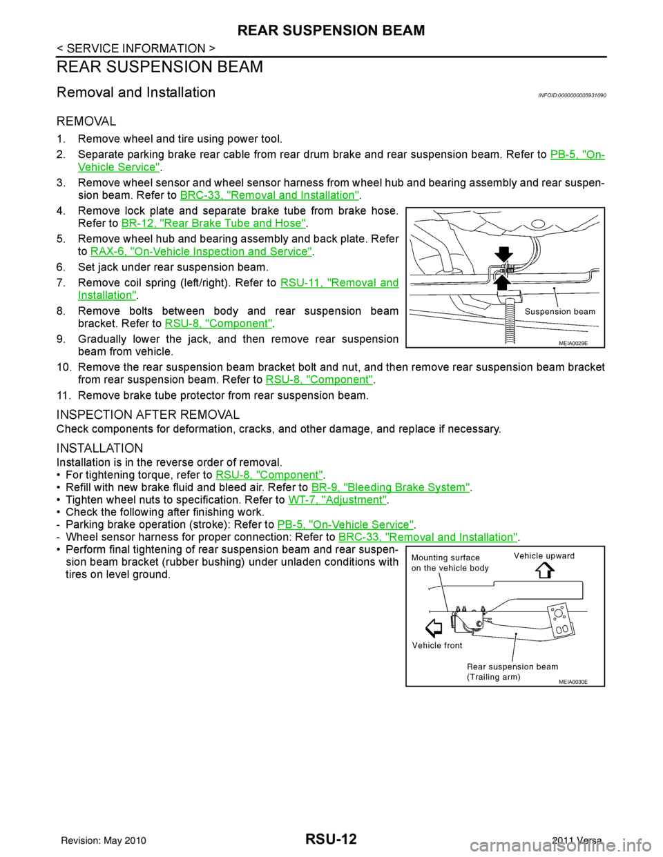
• Perform final tightening of rear suspension beam and rear suspen-
sion beam bracket (rubber bushing) under unladen conditions with
tires on level ground.
MEIA0029E
MEIA0030E
Revision: May 2010 2011 Versa
Page 3718 of 3787

PRECAUTIONSSTC-31
< PRECAUTION > [EPS]
C
D
E
F
H I
J
K L
M A
B
STC
N
O P
5. When the repair work is completed, return the ignition switch to the ″LOCK ″ position before connecting
the battery cables. (At this time, the steering lock mechanism will engage.)
6. Perform a self-diagnosis check of al l control units using CONSULT-III.
Service Notice or Precaution for EPS SystemINFOID:0000000005931271
CAUTION:
Check or confirm the following item wh en performing the trouble diagnosis.
• Check any possible causes by interviewing the symptom and it’s condition from the customer if any
malfunction, such as EPS warn ing lamp turns ON, occurs.
• Check if air pressure and size of tires are proper, the specified part is used for the steering wheel,
and control unit is genuine part.
• Check if the connection of steer ing column assembly and steering gear assembly is proper (there is
not looseness of mounting bolts, damage of rods, boots or sealants, and leakage of grease, etc).
• Check if the wheel alignment is adjusted properly.
• Check if there is any damage or modification to su spension or body resulting in increased weight or
altered ground clearance.
• Check if installation conditions of each link and suspension are proper.
• Check if the battery voltage is proper
• Check connection conditions of each connector are proper.
• Before connecting or disconnect ing the EPS control unit har-
ness connector, turn ignition switch “OFF” and disconnect
battery ground cable. Because battery voltage is applied to
EPS control unit even if igniti on switch is turned “OFF”.
• When connecting or disconnect ing pin connectors into or
from EPS control unit, take care not to damage pin terminals
(bend or break).
When connecting pin connectors, make sure that there are no
bends or breaks on EPS control unit pin terminal.
• Before replacing EPS control unit, perform EPS control unit input/output signal inspectio n and make sure whether EPS
control unit functions properly or not. Refer to STC-20, "
Ref-
erence Value".
SEF289H
SEF291H
SDIA1848E
Revision: May 2010 2011 Versa
Page 3719 of 3787
WT-1
SUSPENSION
C
DF
G H
I
J
K L
M
SECTION WT
A
B
WT
N
O PCONTENTS
ROAD WHEELS & TIRES
SERVICE INFORMATION .. ..........................2
PRECAUTIONS .............................................. .....2
Precaution for Supplemental Restraint System
(SRS) "AIR BAG" and "SEAT BELT PRE-TEN-
SIONER" ............................................................. ......
2
Precaution Necessary for Steering Wheel Rota-
tion After Battery Disconnect ............................... ......
2
PREPARATION ...................................................4
Special Service Tool ........................................... ......4
Commercial Service Tool ..........................................4
NOISE, VIBRATION AND HARSHNESS
(NVH) TROUBLESHOOTING .............................
5
NVH Troubleshooting Chart ................................ ......5
ROAD WHEEL ....................................................6
Inspection ............................................................ ......6
ROAD WHEEL TIRE ASSEMBLY ......................7
Adjustment .......................................................... ......7
TIRE PRESSURE MONITORING SYSTEM ........9
System Component ............................................. ......9
System Description ...................................................9
CAN COMMUNICATION ....................................11
System Description ............................................. ....11
TROUBLE DIAGNOSES ....................................12
Wiring Diagram- T/WARN - .....................................12
Terminal and Reference Value for BCM .................12
ID Registration Procedure .......................................13
Transmitter Wake Up Operation .............................14
CONSULT-III Function (BCM) .................................14
How to Perform Trouble Diagnosis for Quick and
Accurate Repair ................................................... ....
15
Preliminary Check ...................................................16
Self-Diagnosis (With CONSULT-III) ........................16
Self-Diagnosis (Without CONSULT-III) ...................17
TROUBLE DIAGNOSIS FOR SELF-DIAG-
NOSTIC ITEMS .................................................
20
Data from Transmitter Not Being Received .............20
Transmitter Malfunction ...........................................20
Transmitter Pressure Malfunction ............................21
Vehicle Speed Signal .......................................... ....21
Vehicle Ignition Signal .............................................22
TROUBLE DIAGNOSIS FOR SYMPTOMS ......23
Low Tire Pressure Warning Lamp Does Not Come
On When Ignition Switch Is Turned On ...................
23
Low Tire Pressure Warning Lamp Stays On When
Ignition Switch Is Turned On ............................... ....
23
Low Tire Pressure Warning Lamp Flashes When
Ignition Switch Is Turned On ...................................
24
Hazard Warning Lamps Flash When Ignition
Switch Is Turned On ................................................
25
ID Registration Cannot Be Completed ....................25
REMOVAL AND INSTALLATION .....................26
Transmitter (Pressure Sens or) ................................26
SERVICE DATA AND SPECIFICATIONS
(SDS) .................................................................
28
Road Wheel ......................................................... ....28
Tire ..........................................................................28
Revision: May 2010 2011 Versa
Page 3723 of 3787
NOISE, VIBRATION AND HARSHNESS (NVH) TROUBLESHOOTINGWT-5
< SERVICE INFORMATION >
C
DF
G H
I
J
K L
M A
B
WT
N
O P
NOISE, VIBRATION AND HARSHN ESS (NVH) TROUBLESHOOTING
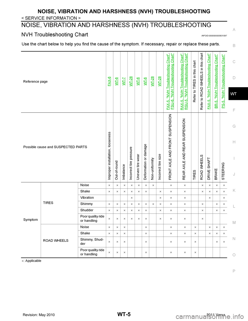
NVH Troubleshooting ChartINFOID:0000000005931097
Use the chart below to help you find t he cause of the symptom. If necessary, repair or replace these parts.
×: Applicable
Reference page
FAX-6WT-6
WT-7
WT-28WT-6
WT-6
WT-28WT-28
FAX-5, "
NVH Troubleshooting Chart
",
FSU-6, "
NVH Troubleshooting Chart
"
RAX-5, "
NVH Troubleshooting Chart
",
RSU-5, "
NVH Troubleshooting Chart
"
Refer to TIRES in this chart
Refer to ROAD WHEELS in this chart
FAX-5, "
NVH Troubleshooting Chart
"
BR-5, "
NVH Troubleshooting Chart
"
PS-5, "
NVH Troubleshooting Chart
"
Possible cause and SUSPECTED PARTS
Improper installation, looseness
Out-of-round
Imbalance
Incorrect tire pressure
Uneven tire wear
Deformation or damage
Non-uniformity
Incorrect tire size
FRONT AXLE AND FRONT SUSPENSION
REAR AXLE AND REAR SUSPENSION
TIRES
ROAD WHEELS
DRIVE SHAFT
BRAKE
STEERING
Symptom TIRES Noise
× ×××××× × × ××××
Shake × ××××× × × × ××××
Vibration ××××××
Shimmy × ××××××× × × × ××
Shudder × ××××× × × × × ××
Poor quality ride
or handling × ××××× × × × ×
ROAD WHEELS Noise
× ×× × × × × ×××
Shake × ×× × × × × ×××
Shimmy, Shud-
der ××× × × × × ××
Poor quality ride
or handling ××× × × × ×
Revision: May 2010
2011 Versa
Page 3724 of 3787

WT-6
< SERVICE INFORMATION >
ROAD WHEEL
ROAD WHEEL
InspectionINFOID:0000000005931098
ALUMINUM WHEEL
1. Check tires for wear and improper inflation.
2. Check wheels for deformation, cracks and other damage. If deformed, remove wheel and check wheel
runout.
a. Remove tire from aluminum wheel and mount on a tire balance machine.
b. Set dial indicator as shown.
STEEL WHEEL
1. Check tires for wear and improper inflation.
2. Check wheels for deformation, cracks and other dam age. If deformed, remove wheel and check wheel
runout.
a. Remove tire from steel wheel and mount on a tire balance machine.
b. Set two dial indicators as shown.
c. Set each dial indicator to 0.
d. Rotate wheel and check dial indicators at several points around the circumference of the wheel.
e. Calculate runout at each point as shown.
f. Select maximum positive runout value and the maximum nega- tive value.
Add the two values to determine total runout. In case a positive
or negative value is not available, use the maximum value (neg-
ative or positive) for total runout. If the total runout value
exceeds the limit, replace steel wheel.Wheel runout
(Dial indicator value)
: Refer to
WT-28, "
Road Wheel".
SFA975B
Radial runout = (A+B)/2
Lateral runout = (C+D)/2
Wheel runout : Refer to WT-28, "
Road Wheel".
SEIA0558E
Revision: May 2010 2011 Versa
Page 3726 of 3787
WT-8
< SERVICE INFORMATION >
ROAD WHEEL TIRE ASSEMBLY
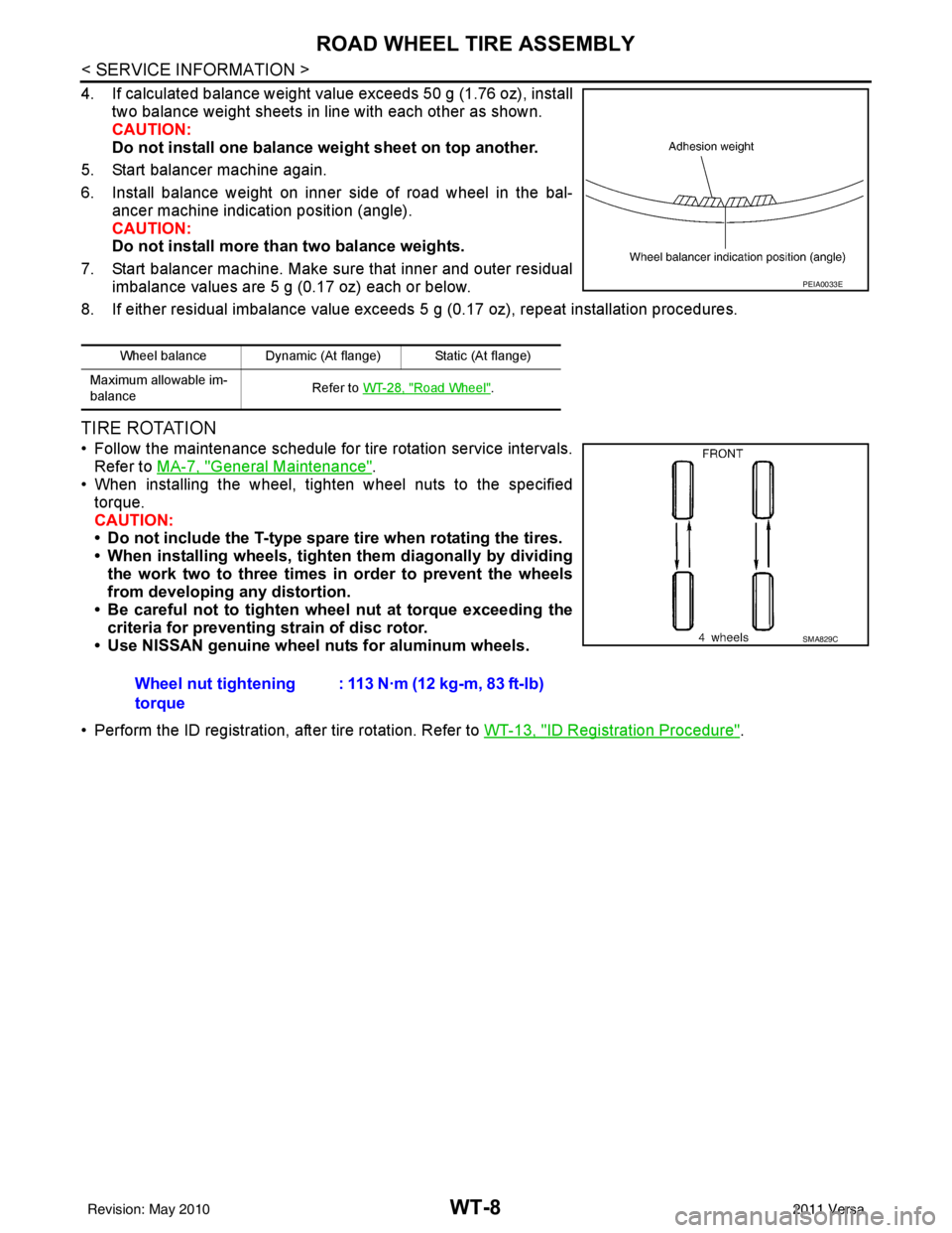
4. If calculated balance weight value exceeds 50 g (1.76 oz), installtwo balance weight sheets in line with each other as shown.
CAUTION:
Do not install one balance weight sheet on top another.
5. Start balancer machine again.
6. Install balance weight on inner side of road wheel in the bal- ancer machine indication position (angle).
CAUTION:
Do not install more than two balance weights.
7. Start balancer machine. Make sure that inner and outer residual imbalance values are 5 g (0.17 oz) each or below.
8. If either residual imbalance value exceeds 5 g (0.17 oz), repeat installation procedures.
TIRE ROTATION
• Follow the maintenance schedule for tire rotation service intervals.
Refer to MA-7, "
General Maintenance".
• When installing the wheel, tighten wheel nuts to the specified
torque.
CAUTION:
• Do not include the T-type spare tire when rotating the tires.
• When installing wheels, tighten them diagonally by dividing
the work two to three times in order to prevent the wheels
from developing any distortion.
• Be careful not to tighten wheel nut at torque exceeding the criteria for preventing strain of disc rotor.
• Use NISSAN genuine wheel nuts for aluminum wheels.
• Perform the ID registration, after tire rotation. Refer to WT-13, "
ID Registration Procedure".
Wheel balance Dynamic (At flange) Static (At flange)
Maximum allowable im-
balance Refer to
WT-28, "
Road Wheel".
PEIA0033E
Wheel nut tightening
torque : 113 N·m (12 kg-m, 83 ft-lb)
SMA829C
Revision: May 2010
2011 Versa