2011 NISSAN LATIO sensor
[x] Cancel search: sensorPage 91 of 3787
AT-74
< SERVICE INFORMATION >
TROUBLE DIAGNOSIS
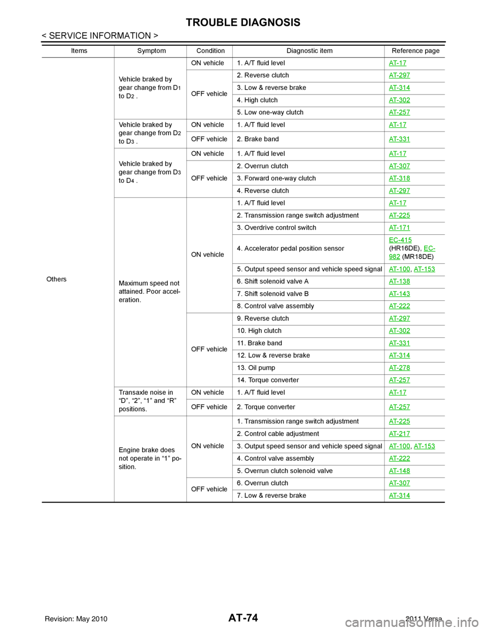
OthersVehicle braked by
gear change from D
1
to D
2 . ON vehicle 1. A/T fluid level
AT- 1 7OFF vehicle2. Reverse clutch
AT- 2 9 73. Low & reverse brakeAT- 3 1 4
4. High clutchAT- 3 0 2
5. Low one-way clutchAT- 2 5 7
Vehicle braked by
gear change from D
2
to D
3 . ON vehicle 1. A/T fluid level
AT- 1 7OFF vehicle 2. Brake bandAT- 3 3 1
Vehicle braked by
gear change from D
3
to D
4 . ON vehicle 1. A/T fluid level
AT- 1 7OFF vehicle2. Overrun clutch
AT- 3 0 73. Forward one-way clutchAT- 3 1 8
4. Reverse clutchAT- 2 9 7
Maximum speed not
attained. Poor accel-
eration.ON vehicle1. A/T fluid level
AT- 1 7
2. Transmission range switch adjustmentAT- 2 2 5
3. Overdrive control switchAT- 1 7 1
4. Accelerator pedal position sensorEC-415
(HR16DE), EC-
982 (MR18DE)
5. Output speed sensor and vehicle speed signal AT- 1 0 0
, AT- 1 5 3
6. Shift solenoid valve A AT- 1 3 8
7. Shift solenoid valve BAT- 1 4 3
8. Control valve assemblyAT- 2 2 2
OFF vehicle9. Reverse clutch
AT- 2 9 7
10. High clutchAT- 3 0 2
11. Brake bandAT- 3 3 1
12. Low & reverse brakeAT- 3 1 4
13. Oil pumpAT- 2 7 8
14. Torque converterAT- 2 5 7
Transaxle noise in
“D”, “2”, “1” and “R”
positions.ON vehicle 1. A/T fluid level
AT- 1 7
OFF vehicle 2. Torque converterAT- 2 5 7
Engine brake does
not operate in “1” po-
sition.ON vehicle1. Transmission range switch adjustment
AT- 2 2 5
2. Control cable adjustmentAT- 2 1 7
3. Output speed sensor and vehicle speed signalAT- 1 0 0, AT- 1 5 3
4. Control valve assembly AT- 2 2 2
5. Overrun clutch solenoid valveAT- 1 4 8
OFF vehicle6. Overrun clutch
AT- 3 0 77. Low & reverse brakeAT- 3 1 4
ItemsSymptom Condition Diagnostic itemReference page
Revision: May 2010 2011 Versa
Page 92 of 3787
TROUBLE DIAGNOSISAT-75
< SERVICE INFORMATION >
DE
F
G H
I
J
K L
M A
B
AT
N
O P
TCM Terminal and Reference ValueINFOID:0000000005928104
TCM HARNESS CONNECTOR TERMINAL LAYOUT
Terminals and Reference Values for TCM
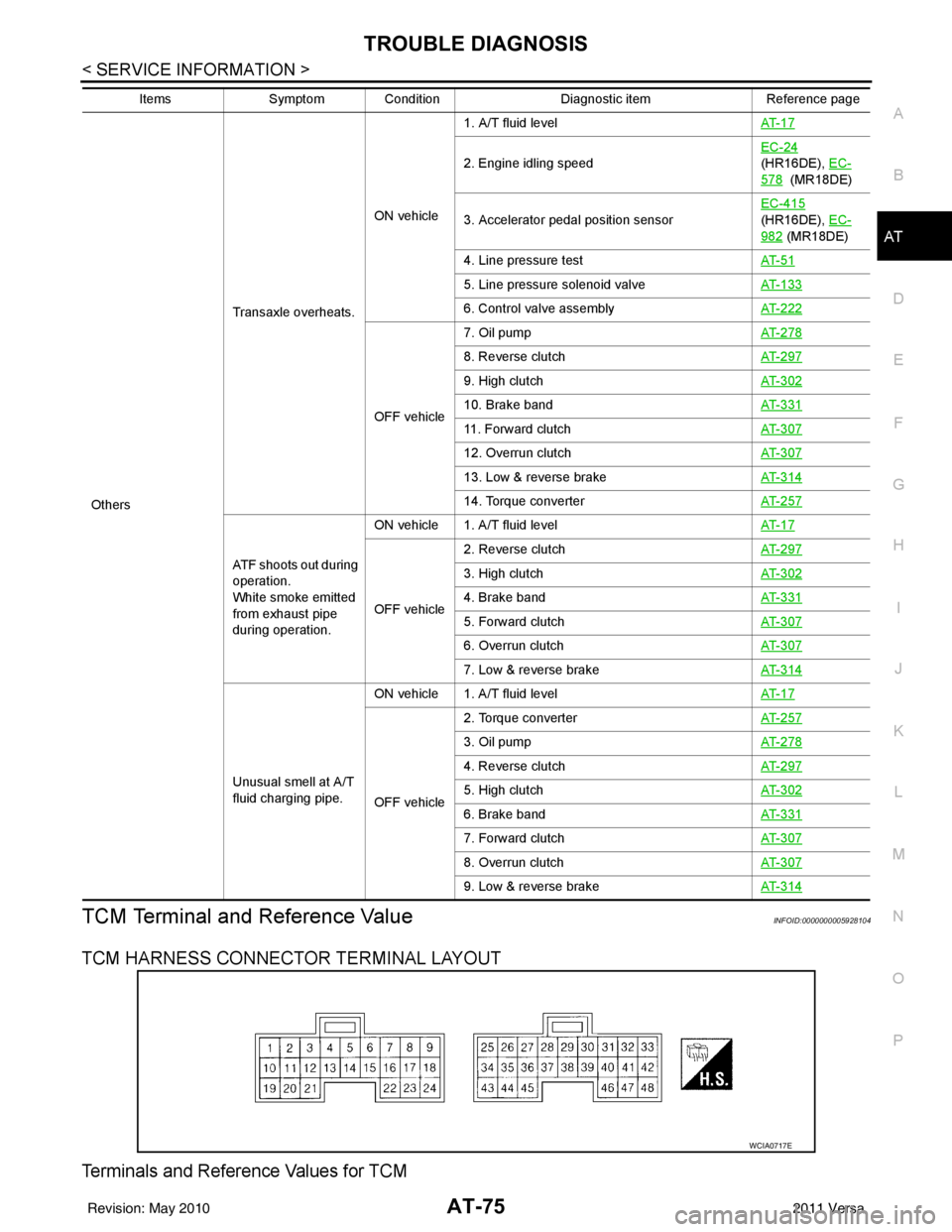
Others Transaxle overheats.
ON vehicle
1. A/T fluid level
AT- 1 7
2. Engine idling speedEC-24
(HR16DE), EC-
578 (MR18DE)
3. Accelerator pedal position sensor EC-415
(HR16DE), EC-
982 (MR18DE)
4. Line pressure test AT- 5 1
5. Line pressure solenoid valveAT- 1 3 3
6. Control valve assemblyAT- 2 2 2
OFF vehicle7. Oil pump
AT- 2 7 8
8. Reverse clutchAT- 2 9 7
9. High clutchAT- 3 0 2
10. Brake bandAT- 3 3 1
11. Forward clutchAT- 3 0 7
12. Overrun clutchAT- 3 0 7
13. Low & reverse brakeAT- 3 1 4
14. Torque converterAT- 2 5 7
ATF shoots out during
operation.
White smoke emitted
from exhaust pipe
during operation.ON vehicle 1. A/T fluid level
AT- 1 7
OFF vehicle2. Reverse clutch
AT- 2 9 7
3. High clutchAT- 3 0 2
4. Brake bandAT- 3 3 1
5. Forward clutchAT- 3 0 7
6. Overrun clutchAT- 3 0 7
7. Low & reverse brakeAT- 3 1 4
Unusual smell at A/T
fluid charging pipe.ON vehicle 1. A/T fluid level
AT- 1 7
OFF vehicle2. Torque converter
AT- 2 5 7
3. Oil pumpAT- 2 7 8
4. Reverse clutchAT- 2 9 7
5. High clutchAT- 3 0 2
6. Brake bandAT- 3 3 1
7. Forward clutchAT- 3 0 7
8. Overrun clutchAT- 3 0 7
9. Low & reverse brakeAT- 3 1 4
ItemsSymptom Condition Diagnostic itemReference page
WCIA0717E
Revision: May 2010 2011 Versa
Page 93 of 3787
AT-76
< SERVICE INFORMATION >
TROUBLE DIAGNOSIS
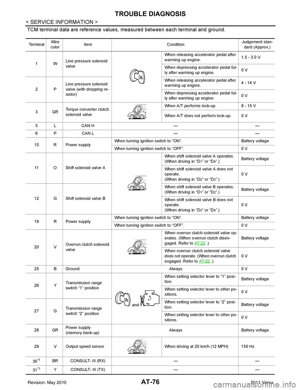
TCM terminal data are reference values, measured between each terminal and ground.
Te r m i n a lWire
color Item
ConditionJudgement stan-
dard (Approx.)
1W Line pressure solenoid
valve When releasing accelerator pedal after
warming up engine.
1.5 - 3.0 V
When depressing accelerator pedal ful-
ly after warming up engine. 0 V
2P Line pressure solenoid
valve (with dropping re-
sistor) When releasing accelerator pedal after
warming up engine.
4 - 14 V
When depressing accelerator pedal ful-
ly after warming up engine. 0 V
3GR Torque converter clutch
solenoid valve When A/T performs lock-up.
8 - 15 V
When A/T does not perform lock-up. 0 V
5 L CAN H ——
6 P CAN L ——
10 R Power supply When turning ignition switch to “ON”.
Battery voltage
When turning ignition switch to “OFF”. 0 V
11 O Shift solenoid valve A When shift solenoid valve A operates.
(When driving in “D
1” or “D4”.)
Battery voltage
When shift solenoid valve A does not
operate.
(When driving in “D
2” or “D3”.) 0 V
12 G Shift solenoid valve B When shift solenoid valve B operates.
(When driving in “D
1” or “D2”.)
Battery voltage
When shift solenoid valve B does not
operate.
(When driving in “D
3” or “D4”.) 0 V
19 R Power supply When turning ignition switch to “ON”.
Battery voltage
When turning ignition switch to “OFF”. 0 V
20 V Overrun clutch solenoid
valve When overrun clutch solenoid valve op-
erates. (When overrun clutch disen-
gaged. Refer to
AT- 2 2
.) Battery voltage
When overrun clutch solenoid valve
does not operate. (When overrun clutch
engaged. Refer to AT- 2 2
.)0 V
25 B Ground Always0 V
26 Y Transmission range
switch “1” position
and When setting selector lever to “1” posi-
tion.
Battery voltage
When setting selector lever to other po-
sitions. 0 V
27 G Transmission range
switch “2” position When setting selector lever to “2” posi-
tion.
Battery voltage
When setting selector lever to other po-
sitions. 0 V
28 GR Power supply
(memory back-up) Always
Battery voltage
29 V Output speed sensor When driving at 20 km/h (12 MPH) 150 Hz
30
*1BR CONSULT- III (RX) ——
31
*1Y CONSULT- III (TX) ——
Revision: May 2010 2011 Versa
Page 94 of 3787
TROUBLE DIAGNOSISAT-77
< SERVICE INFORMATION >
DE
F
G H
I
J
K L
M A
B
AT
N
O P
*1: These terminals are connected to the data link connector.
*2: These terminals are connected to the ECM.
CONSULT-III Function (TRANSMISSION)INFOID:0000000005928105
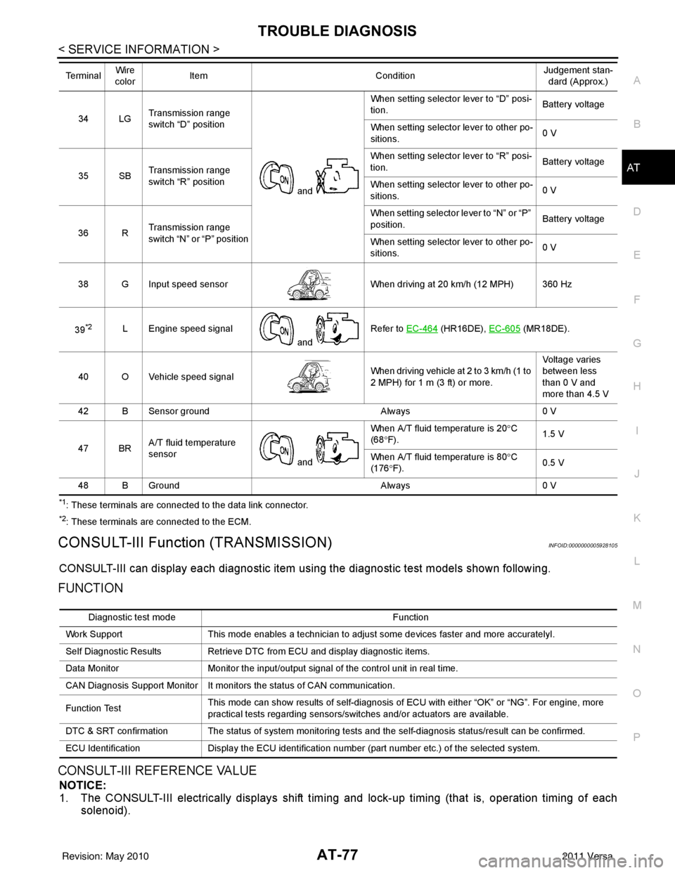
CONSULT-III can display each diagnostic item using the diagnostic test models shown following.
FUNCTION
CONSULT-III REFERENCE VALUE
NOTICE:
1. The CONSULT-III electrically displays shift timi ng and lock-up timing (that is, operation timing of each
solenoid).
34 LG Transmission range
switch “D” position
and When setting selector lever to “D” posi-
tion.
Battery voltage
When setting selector lever to other po-
sitions. 0 V
35 SB Transmission range
switch “R” position When setting selector lever to “R” posi-
tion.
Battery voltage
When setting selector lever to other po-
sitions. 0 V
36 R Transmission range
switch “N” or “P” position When setting selector
lever to “N” or “P”
position. Battery voltage
When setting selector lever to other po-
sitions. 0 V
38 G Input speed sensor When driving at 20 km/h (12 MPH) 360 Hz
39
*2L Engine speed signal and Refer to EC-464 (HR16DE),
EC-605 (MR18DE).
40 O Vehicle speed signal When driving vehicle at 2 to 3 km/h (1 to
2 MPH) for 1 m (3 ft) or more.Voltage varies
between less
than 0 V and
more than 4.5 V
42 B Sensor ground Always0 V
47 BR A/T fluid temperature
sensor
and When A/T fluid temperature is 20°
C
(68 °F). 1.5 V
When A/T fluid temperature is 80° C
(176 °F). 0.5 V
48 B Ground Always0 V
Te r m i n a l
Wire
color Item
ConditionJudgement stan-
dard (Approx.)
Diagnostic test mode Function
Work Support This mode enables a technician to adjust some devices faster and more accuratelyI.
Self Diagnostic Results Retrieve DTC from ECU and display diagnostic items.
Data Monitor Monitor the input/output signal of the control unit in real time.
CAN Diagnosis Support Monitor It monitors the status of CAN communication.
Function Test This mode can show results of self-diagnosis of ECU with either “OK” or “NG”. For engine, more
practical tests regarding sensors/switches and/or actuators are available.
DTC & SRT confirmation The status of system monitoring tests and the self-diagnosis status/result can be confirmed.
ECU Identification Display the ECU identification number (part number etc.) of the selected system.
Revision: May 2010 2011 Versa
Page 96 of 3787
TROUBLE DIAGNOSISAT-79
< SERVICE INFORMATION >
DE
F
G H
I
J
K L
M A
B
AT
N
O P
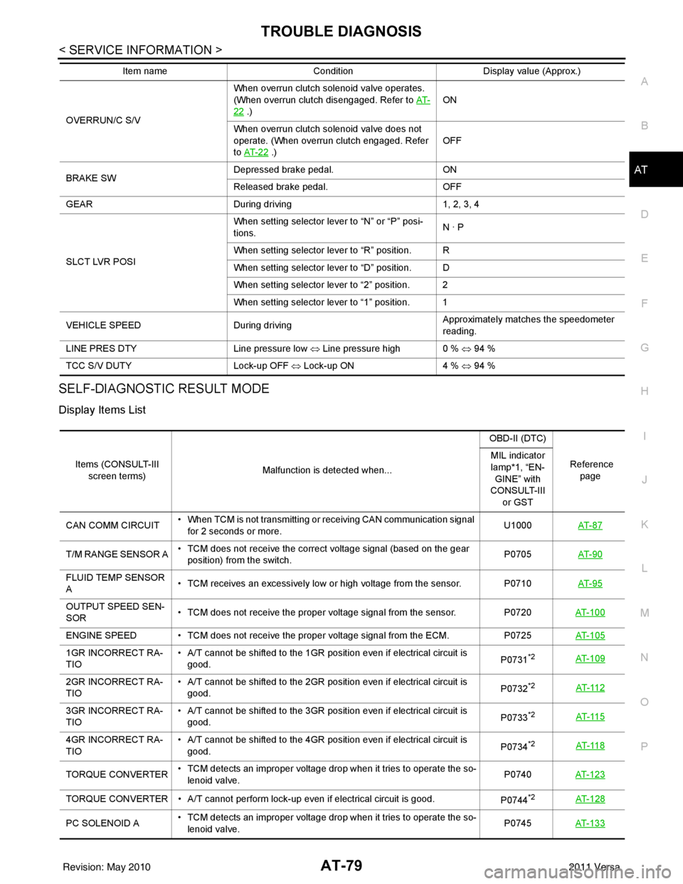
SELF-DIAGNOSTIC RESULT MODE
Display Items List
OVERRUN/C S/V When overrun clutch solenoid valve operates.
(When overrun clutch disengaged. Refer to
AT-22 .) ON
When overrun clutch solenoid valve does not
operate. (When overrun clutch engaged. Refer
to AT- 2 2
.) OFF
BRAKE SW Depressed brake pedal.
ON
Released brake pedal. OFF
GEAR During driving 1, 2, 3, 4
SLCT LVR POSI When setting selector lever to “N” or “P” posi-
tions.
N · P
When setting selector lever to “R” position. R
When setting selector lever to “D” position. D
When setting selector lever to “2” position. 2
When setting selector lever to “1” position. 1
VEHICLE SPEED During driving Approximately matches the speedometer
reading.
LINE PRES DTY Line pressure low ⇔ Line pressure high 0 % ⇔ 94 %
TCC S/V DUTY Lock-up OFF ⇔ Lock-up ON 4 % ⇔ 94 %
Item name
Condition Display value (Approx.)
Items (CONSULT-III
screen terms) Malfunction is detected when... OBD-II (DTC)
Reference page
MIL indicator
lamp*1, “EN-
GINE” with
CONSULT-III
or GST
CAN COMM CIRCUIT • When TCM is not transmitting or receiving CAN communication signal
for 2 seconds or more. U1000
AT- 8 7
T/M RANGE SENSOR A • TCM does not receive the correct voltage signal (based on the gear
position) from the switch. P0705
AT- 9 0
FLUID TEMP SENSOR
A • TCM receives an excessively low or high voltage from the sensor. P0710
AT- 9 5
OUTPUT SPEED SEN-
SOR• TCM does not receive the proper voltage signal from the sensor.
P0720AT- 1 0 0
ENGINE SPEED • TCM does not re ceive the proper voltage signal from the ECM. P0725AT- 1 0 5
1GR INCORRECT RA-
TIO • A/T cannot be shifted to the 1GR position even if electrical circuit is
good. P0731*2AT- 1 0 9
2GR INCORRECT RA-
TIO• A/T cannot be shifted to the 2GR position even if electrical circuit is
good. P0732*2AT- 11 2
3GR INCORRECT RA-
TIO• A/T cannot be shifted to the 3GR position even if electrical circuit is
good. P0733*2AT- 11 5
4GR INCORRECT RA-
TIO• A/T cannot be shifted to the 4GR position even if electrical circuit is
good. P0734*2AT- 11 8
TORQUE CONVERTER• TCM detects an improper voltage drop when it tries to operate the so-
lenoid valve. P0740
AT- 1 2 3
TORQUE CONVERTER • A/T cannot perform lock-up even if electrical circuit is good.
P0744*2AT- 1 2 8
PC SOLENOID A• TCM detects an improper voltage drop when it tries to operate the so-
lenoid valve. P0745
AT- 1 3 3
Revision: May 2010 2011 Versa
Page 97 of 3787

AT-80
< SERVICE INFORMATION >
TROUBLE DIAGNOSIS
*1: Refer to AT- 4 1 , "Malfunction Indicator Lamp (MIL)" .
*2: These malfunctions cannot be displayed MIL if another malfunction is assigned to MIL.
DATA MONITOR MODE
Display Items List
X: Standard, —: Not applicable, : Option
SHIFT SOLENOID A • TCM detects an improper voltage drop when it tries to operate the so-
lenoid valve. P0750
AT- 1 3 8
SHIFT SOLENOID B • TCM detects an improper voltage drop when it tries to operate the so-
lenoid valve. P0755
AT- 1 4 3
OVER CLUTCH SOLE-
NOID • TCM detects an improper voltage drop when it tries to operate the so-
lenoid valve. P1760
AT- 1 4 8
VHCL SPEED SEN-
MTR • TCM does not receive the proper voltage signal from the sensor.
—AT- 1 5 3
BATT/FLUID TEMP
SEN • TCM receives an excessively low or high voltage from the sensor.
—AT- 1 5 6
INPUT SPEED SEN-
SOR A • TCM does not receive proper voltage signal from sensor.
—AT- 1 6 2
CONTROL UNIT (RAM) • TCM memory (RAM) is malfunctioning. —AT- 1 6 7
CONTROL UNIT (ROM) • TCM memory (ROM) is malfunctioning. —AT- 1 6 7
No failure
(NO SELF DIAGNOS-
TIC FAILURE INDICAT-
ED FURTHER
TESTING MAY BE RE-
QUIRED) • No failure has been detected.
——
Items (CONSULT-III
screen terms) Malfunction is detected when... OBD-II (DTC)
Reference page
MIL indicator
lamp*1, “EN-
GINE” with
CONSULT-III or GST
Monitored item (Unit) Monitor Item Selection
Remarks
TCM INPUT
SIGNALS MAIN SIG-
NALS SELEC-
TION FROM MENU
VHCL/S SE-A/T (km/h) X— Output speed sensor
VHCL/S SE-MTR (km/h) X— Vehicle speed display may not be accu-
rate under approx. 10 km/h (6 mph). It
may not indicate 0 km/h (0 mph) when
vehicle is stationary.
THRTL POS SEN (V) X—
FLUID TEMP SE (V) X—
BATTERY VOLT (V) X—
ENGINE SPEED (rpm) XX
INPUT SPEED (rpm) X—
OVERDRIVE SW (ON/OFF) X—
PN POSI SW (ON/OFF) X—
R POSITION SW (ON/OFF) X—
D POSITION SW (ON/OFF) X—
Revision: May 2010 2011 Versa
Page 101 of 3787

AT-84
< SERVICE INFORMATION >
TROUBLE DIAGNOSIS
OD OFF indicator lamp
All judgement flickers are the same.
All circuits that can be confirmed by self-diagnosis are OK. 1st judgement flicker is longer than others.
Output speed sensor circuit is short-circuited or disconnected.
⇒ Go to
AT- 1 0 0
.
2nd judgement flicker is longer than others.
Vehicle speed signal circuit is short-circuited or disconnected.
⇒ Go to AT- 1 5 3
. 4th judgement flicker is longer than others.
Shift solenoid valve A circuit is short-circuited or disconnected.
⇒ Go to
AT- 1 3 8 .
5th judgement flicker is longer than others.
Shift solenoid valve B circuit is short-circuited or disconnected.
⇒ Go to AT- 1 4 3
. 6th judgement flicker is longer than others.
Overrun clutch solenoid valve circuit is short-circuited or discon-
nected.
⇒ Go to
AT- 1 4 8
.
SCIA7161ESCIA5591E
SCIA5592ESCIA5594E
SCIA5595ESCIA5596E
Revision: May 2010 2011 Versa
Page 102 of 3787

TROUBLE DIAGNOSISAT-85
< SERVICE INFORMATION >
DE
F
G H
I
J
K L
M A
B
AT
N
O P
7th judgement flicker is longer than others.
Torque converter clutch solenoid valve circuit is short-circuited or
disconnected.
⇒ Go to AT- 1 2 3
. 8th judgement flicker is longer than others.
A/T fluid temperature sensor is disconnected or TCM power supply
circuit is damaged.
⇒ Go to
AT- 1 5 6 .
9th judgement flicker is longer than others.
Engine speed signal circuit is short-circuited or disconnected.
⇒ Go to AT- 1 0 5
. 10th judgement flicker is longer than others.
Input speed sensor circuit is short-circuited or disconnected.
⇒ Go to
AT- 1 6 2 .
OD OFF indicator lamp
SCIA5597ESCIA5598E
SCIA5599ESCIA7082E
Revision: May 2010
2011 Versa