2011 NISSAN LATIO wheel torque
[x] Cancel search: wheel torquePage 2697 of 3787
FSU-12
< SERVICE INFORMATION >
COIL SPRING AND STRUT
COIL SPRING AND STRUT
Removal and InstallationINFOID:0000000005930902
REMOVAL
1. Remove cowl top panel. Refer to EI-24, "Removal and Installation".
2. Remove front tires using power tool.
3. Remove harness of wheel sensor from strut assembly. Refer to BRC-33, "
Removal and Installation".
CAUTION:
Do not pull on wheel sensor harness.
4. Remove brake hose lock plate. Refer to BR-12, "
Rear Brake Tube and Hose".
5. Remove the nut on the upper side of stabilizer connecting rod using power tool, and then remove stabi- lizer connecting rod from strut assembly.
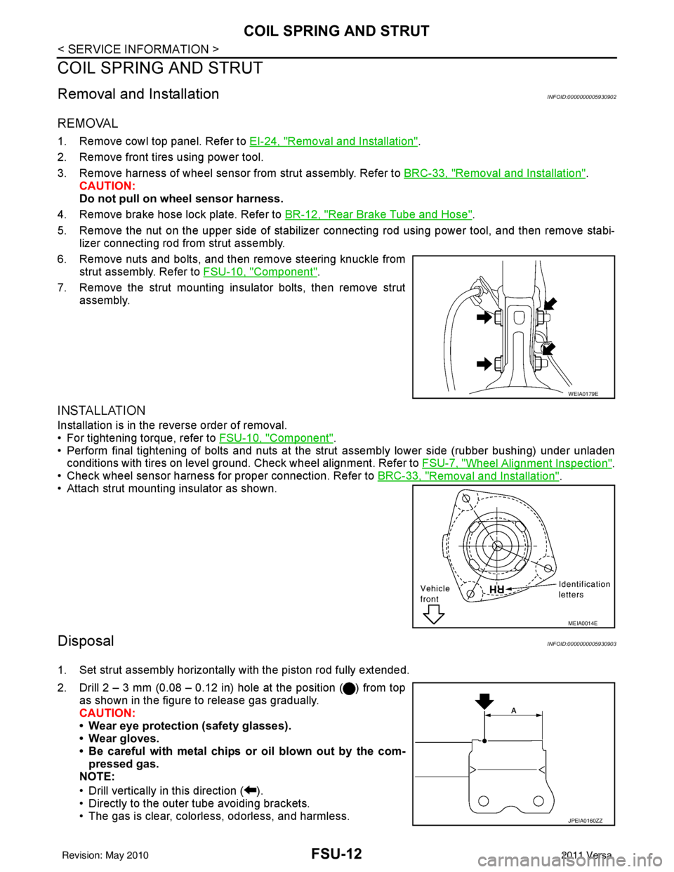
6. Remove nuts and bolts, and then remove steering knuckle from strut assembly. Refer to FSU-10, "
Component".
7. Remove the strut mounting insulator bolts, then remove strut assembly.
INSTALLATION
Installation is in the reverse order of removal.
• For tightening torque, refer to FSU-10, "
Component".
• Perform final tightening of bolts and nuts at the strut assembly lower side (rubber bushing) under unladen
conditions with tires on level ground. Check wheel alignment. Refer to FSU-7, "
Wheel Alignment Inspection".
• Check wheel sensor harness for proper connection. Refer to BRC-33, "
Removal and Installation".
• Attach strut mounting insulator as shown.
DisposalINFOID:0000000005930903
1. Set strut assembly horizontally with the piston rod fully extended.
2. Drill 2 – 3 mm (0.08 – 0.12 in) hole at the position ( ) from top
as shown in the figure to release gas gradually.
CAUTION:
• Wear eye protection (safety glasses).
• Wear gloves.
• Be careful with metal chips or oil blown out by the com-pressed gas.
NOTE:
• Drill vertically in this direction ( ).
• Directly to the outer tube avoiding brackets.
• The gas is clear, colorless, odorless, and harmless.
WEIA0179E
MEIA0014E
JPEIA0160ZZ
Revision: May 2010 2011 Versa
Page 2700 of 3787
TRANSVERSE LINKFSU-15
< SERVICE INFORMATION >
C
DF
G H
I
J
K L
M A
B
FSU
N
O P
TRANSVERSE LINK
Removal and InstallationINFOID:0000000006414956
REMOVAL
1. Remove wheel and tire. Refer to WT-7, "Adjustment".
2. Remove transverse link ball joint nut and bolt. Then, remove transverse link from steering knuckle.
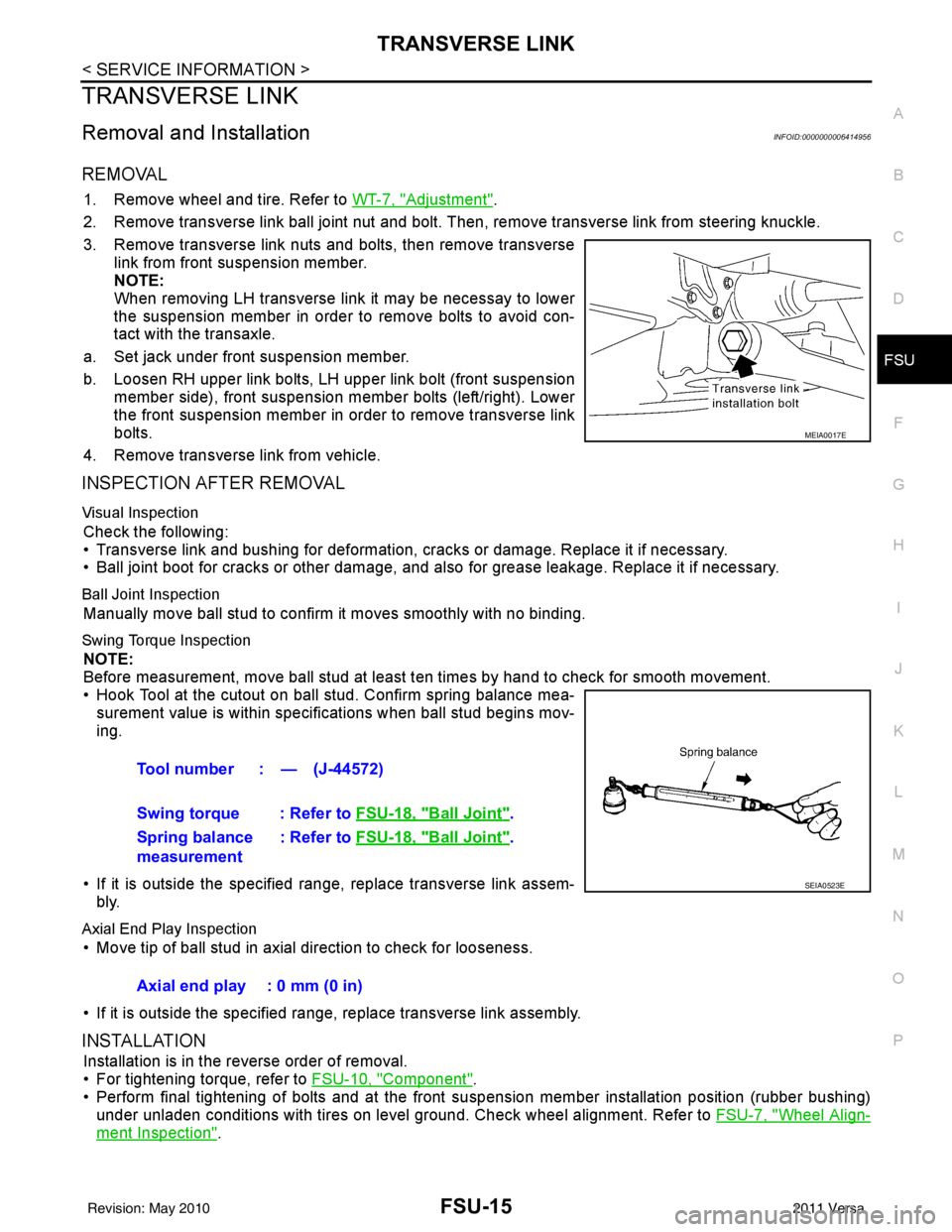
3. Remove transverse link nuts and bolts, then remove transverse link from front suspension member.
NOTE:
When removing LH transverse link it may be necessay to lower
the suspension member in order to remove bolts to avoid con-
tact with the transaxle.
a. Set jack under front suspension member.
b. Loosen RH upper link bolts, LH upper link bolt (front suspension member side), front suspension member bolts (left/right). Lower
the front suspension member in order to remove transverse link
bolts.
4. Remove transverse link from vehicle.
INSPECTION AFTER REMOVAL
Visual Inspection
Check the following:
• Transverse link and bushing for deformation, cracks or damage. Replace it if necessary.
• Ball joint boot for cracks or other damage, and also for grease leakage. Replace it if necessary.
Ball Joint Inspection
Manually move ball stud to confirm it moves smoothly with no binding.
Swing Torque Inspection
NOTE:
Before measurement, move ball stud at least ten times by hand to check for smooth movement.
• Hook Tool at the cutout on ball stud. Confirm spring balance mea- surement value is within specifications when ball stud begins mov-
ing.
• If it is outside the specified range, replace transverse link assem- bly.
Axial End Play Inspection
• Move tip of ball stud in axial direction to check for looseness.
• If it is outside the specified range, replace transverse link assembly.
INSTALLATION
Installation is in the reverse order of removal.
• For tightening torque, refer to FSU-10, "
Component".
• Perform final tightening of bolts and at the front suspension member installation position (rubber bushing)
under unladen conditions with tires on level ground. Check wheel alignment. Refer to FSU-7, "
Wheel Align-
ment Inspection".
MEIA0017E
Tool number : — (J-44572)
Swing torque : Refer to FSU-18, "
Ball Joint".
Spring balance
measurement : Refer to
FSU-18, "
Ball Joint".
SEIA0523E
Axial end play : 0 mm (0 in)
Revision: May 2010 2011 Versa
Page 2705 of 3787

GI-1
GENERAL INFORMATION
C
DE
F
G H
I
J
K L
M B
GI
SECTION GI
N
O P
CONTENTS
GENERAL INFORMATION
SERVICE INFORMATION .. ..........................2
PRECAUTIONS .............................................. .....2
Description .......................................................... ......2
Precaution for Supplemental Restraint System
(SRS) "AIR BAG" and "SEAT BELT PRE-TEN-
SIONER" ...................................................................
2
Precaution Necessary for Steering Wheel Rota-
tion After Battery Disconnect ............................... ......
2
General Precaution ...................................................3
Precaution for Three Way Catalyst ...........................4
Precaution for Fuel (Unleaded Regular Gasoline
Recommended) .........................................................
4
Precaution for Multiport Fuel Injection System or
Engine Control System .............................................
5
Precaution for Hoses .................................................5
Precaution for Engine Oils ........................................6
Precaution for Air Conditioning .................................6
HOW TO USE THIS MANUAL ............................7
Description .......................................................... ......7
Terms ........................................................................7
Units ..........................................................................7
Contents ....................................................................7
Relation between Illustrations and Descriptions .......8
Component ................................................................8
How to Follow Trouble Diagnosis ..............................9
How to Read Wiring Diagram ..................................13
Abbreviations ...................................................... ....20
SERVICE INFORMATION FOR ELECTRICAL
INCIDENT ...........................................................
22
How to Check Terminal ...........................................22
How to Perform Efficient Diagnosis for an Electri-
cal Incident .......................................................... ....
25
Control Units and Electrical Parts ............................32
CONSULT-III CHECKING SYSTEM .................35
Description ...............................................................35
Function and System Application ............................35
CONSULT-III Data Link Connector (DLC) Circuit ....36
LIFTING POINT .................................................38
Special Service Tool ................................................38
Garage Jack and Safety Stand and 2-Pole Lift .......38
Board-On Lift ...........................................................39
TOW TRUCK TOWING .....................................40
Tow Truck Towing ...................................................40
Vehicle Recovery (Freeing a Stuck Vehicle) ...........40
TIGHTENING TORQUE OF STANDARD
BOLTS ...............................................................
41
Tightening Torque Table .........................................41
RECOMMENDED CHEMICAL PRODUCTS
AND SEALANTS ...............................................
42
Recommended Chemical Product and Sealant .......42
IDENTIFICATION INFORMATION ....................43
Model Variation ........................................................43
Dimensions ..............................................................46
Wheels & Tires ........................................................46
TERMINOLOGY ................................................47
SAE J1930 Terminology List ...................................47
Revision: May 2010 2011 Versa
Page 3214 of 3787
CHASSIS AND BODY MAINTENANCEMA-43
< SERVICE INFORMATION >
C
DE
F
G H
I
J
K
M A
B
MA
N
O P
Do not overfill.
4. Drive vehicle for approximately 5 minutes.
5. Re-check A/T fluid level at A/T fluid temperatures of 50° to 80 °C (122° to 176°F) using “HOT” range on A/
T fluid level gauge.
CAUTION:
• When wiping the A/T fluid level gauge, always use lint-free cloth.
• Firmly fix the A/T fluid level ga uge to the A/T fluid charging pipe using the stopper attached.
6. Check A/T fluid condition and make any necessary repairs. Refer to AT-51, "
Inspections Before Trouble
Diagnosis". If the A/T fluid contains frictional material (clutches, bands, etc.), or if the A/T is repaired, over-
hauled, or replaced, inspect and clean the A/T fluid cooler mounted in the radiator. Refer to AT-18, "
A/T
Fluid Cooler Cleaning".
7. Install the removed A/T fluid level gauge into the A/T fluid charging pipe. CAUTION:
Firmly fix the A/T fluid level gaug e to the A/T fluid charging pipe using the stopper attached.
A/T FLUID : Changing A/T FluidINFOID:0000000005931176
1. Warm up A/T fluid.
2. Stop engine.
3. Drain A/T fluid by removing the drain plug. Re install the drain plug to the specified torque.
CAUTION:
Do not reuse drain plug gasket.
4. Refill the transaxle with new specified A/T fluid through the A/T fluid charging pipe. Always refill the tran- saxle with the same volume of A/T fluid that was drained out.
5. Run engine at idle speed for 5 minutes.
6. Check A/T fluid level and condition. Refer to MA-42, "
A/T FLUID : Checking A/T Fluid".
WHEELS
WHEELS : AdjustmentINFOID:0000000006413331
BALANCING WHEELS (ADHESIVE WEIGHT TYPE)
Preparation Before Adjustment
Remove inner and outer balance weights from the r oad wheel using releasing agent, remove double-faced
adhesive tape from the road wheel.
CAUTION:
• Be careful not scratch the road wheel during removal.
• After removing double-faced adhesive tape, wipe clean traces of releasing agent from the road
wheel.
Wheel Balance Adjustment
• If a balancer machine has an adhesive weight mode setting, select the adhesive weight mode setting and skip Step 2. below. If a balancer machine only has the clip-on (rim flange) weight mode setting, follow Step 2.
to calculate the correct size adhesive weight.
1. Set road wheel on balancer machine using the cent er hole as a guide. Start the balancer machine.
2. For tire balance machines that only have a clip-on (ri m flange) weight mode setting, follow this step to cal-
culate the correct size adhesive weight to use. When inner and outer imbalance values are shown on the
balancer machine indicator, multiply outer imbalance value by 5/3 (1.67) to determine balance weight that
should be used. Select the outer balance weight with a value closest to the calculated value above and
install in to the designated outer position of, or at the designated angle in relation to the road wheel.
Drain plug: Refer to
AT-237, "
Component".
Fluid grade and capacity: Refer to MA-14
.
Revision: May 2010 2011 Versa
Page 3216 of 3787
CHASSIS AND BODY MAINTENANCEMA-45
< SERVICE INFORMATION >
C
DE
F
G H
I
J
K
M A
B
MA
N
O P
• Follow the maintenance schedule for tire rotation service intervals. Refer to MA-7, "
General Maintenance".
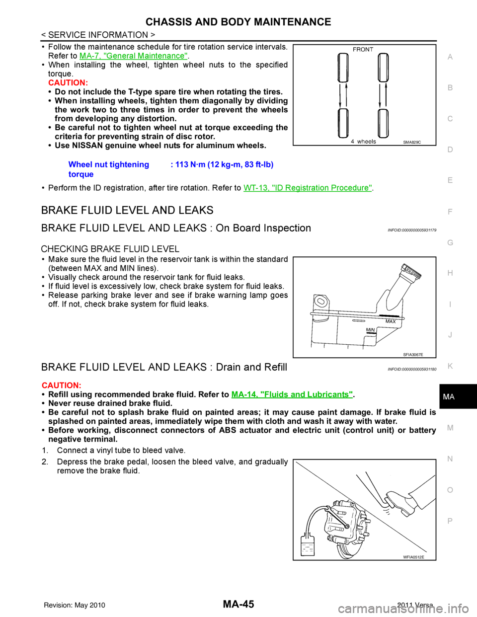
• When installing the wheel, tighten wheel nuts to the specified
torque.
CAUTION:
• Do not include the T-type spare tire when rotating the tires.
• When installing wheels, tighte n them diagonally by dividing
the work two to three times in order to prevent the wheels
from developing any distortion.
• Be careful not to tighten wh eel nut at torque exceeding the
criteria for preventing strain of disc rotor.
• Use NISSAN genuine wheel nuts for aluminum wheels.
• Perform the ID registration, after tire rotation. Refer to WT-13, "
ID Registration Procedure".
BRAKE FLUID LEVEL AND LEAKS
BRAKE FLUID LEVEL AND LEAKS : On Board InspectionINFOID:0000000005931179
CHECKING BRAKE FLUID LEVEL
• Make sure the fluid level in the reservoir tank is within the standard
(between MAX and MIN lines).
• Visually check around the reservoir tank for fluid leaks.
• If fluid level is excessively low, check brake system for fluid leaks.
• Release parking brake lever and see if brake warning lamp goes off. If not, check brake system for fluid leaks.
BRAKE FLUID LEVEL AND LEAKS : Drain and RefillINFOID:0000000005931180
CAUTION:
• Refill using recommended brake fluid. Refer to MA-14, "
Fluids and Lubricants".
• Never reuse drained brake fluid.
• Be careful not to splash brake fluid on painted areas; it may cause paint damage. If brake fluid is
splashed on painted areas, immediately wipe th em with cloth and wash it away with water.
• Before working, disconnect connect ors of ABS actuator and electric unit (control unit) or battery
negative terminal.
1. Connect a vinyl tube to bleed valve.
2. Depress the brake pedal, loosen the bleed valve, and gradually remove the brake fluid.Wheel nut tightening
torque
: 113 N·m (12 kg-m, 83 ft-lb)
SMA829C
SFIA3067E
WFIA0512E
Revision: May 2010
2011 Versa
Page 3498 of 3787
PS-4
< SERVICE INFORMATION >
PREPARATION
PREPARATION
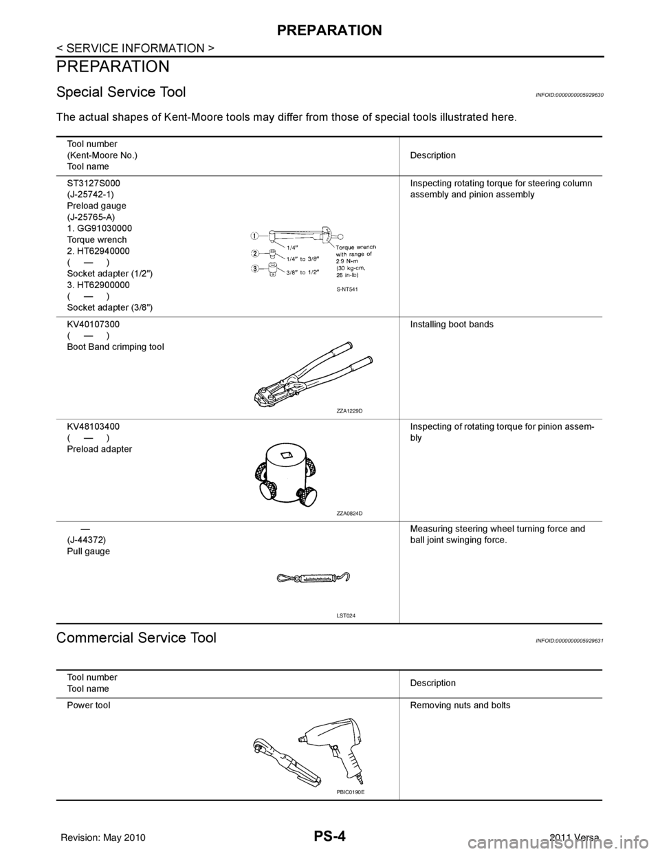
Special Service ToolINFOID:0000000005929630
The actual shapes of Kent-Moore tools may differ from thos e of special tools illustrated here.
Commercial Service ToolINFOID:0000000005929631
Tool number
(Kent-Moore No.)
Tool name Description
ST3127S000
(J-25742-1)
Preload gauge
(J-25765-A)
1. GG91030000
Torque wrench
2. HT62940000
(—)
Socket adapter (1/2")
3. HT62900000
(—)
Socket adapter (3/8") Inspecting rotating torque for steering column
assembly and pinion assembly
KV40107300
(—)
Boot Band crimping tool Installing boot bands
KV48103400
(—)
Preload adapter Inspecting of rotating torque for pinion assem-
bly
—
(J-44372)
Pull gauge Measuring steering wheel turning force and
ball joint swinging force.
S-NT541
ZZA1229D
ZZA0824D
LST024
Tool number
Tool name
Description
Power tool Removing nuts and bolts
PBIC0190E
Revision: May 2010 2011 Versa
Page 3499 of 3787
NOISE, VIBRATION AND HARSHNESS (NVH) TROUBLESHOOTINGPS-5
< SERVICE INFORMATION >
C
DE
F
H I
J
K L
M A
B
PS
N
O P
NOISE, VIBRATION AND HARSHN ESS (NVH) TROUBLESHOOTING
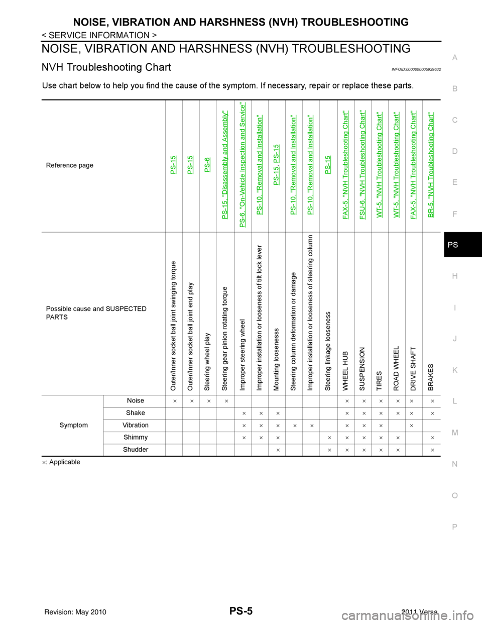
NVH Troubleshooting ChartINFOID:0000000005929632
Use chart below to help you find the cause of the symptom. If necessary, repair or replace these parts.
×: ApplicableReference page
PS-15PS-15PS-6
PS-15, "
Disassembly and Assembly
"
PS-6, "
On-Vehicle Inspection and Service
"
PS-10, "
Removal and Installation
"
PS-15
,
PS-15
PS-10, "
Removal and Installation
"
PS-10, "
Removal and Installation
"
PS-15
FAX-5, "
NVH Troubleshooting Chart
"
FSU-6, "
NVH Troubleshooting Chart
"
WT-5, "
NVH Troubleshooting Chart
"
WT-5, "
NVH Troubleshooting Chart
"
FAX-5, "
NVH Troubleshooting Chart
"
BR-5, "
NVH Troubleshooting Chart
"
Possible cause and SUSPECTED
PA R T S
Outer/Inner socket ball joint swinging torque
Outer/Inner socket ball joint end play
Steering wheel play
Steering gear pinion rotating torque
Improper steering wheel
Improper installation or looseness of tilt lock lever
Mounting loosenesss
Steering column deformation or damage
Improper installation or looseness of steering column
Steering linkage looseness
WHEEL HUB
SUSPENSION
TIRES
ROAD WHEEL
DRIVE SHAFT
BRAKES
Symptom Noise
××× × ××××× ×
Shake ×××××××× ×
Vibration ××××× ××× ×
Shimmy ×××× ×××× ×
Shudder ×× ×××× ×
Revision: May 2010 2011 Versa
Page 3505 of 3787
STEERING COLUMNPS-11
< SERVICE INFORMATION >
C
DE
F
H I
J
K L
M A
B
PS
N
O P
7. Disconnect each switch connector installed to steering column assembly, and then disconnect harness from steering column assembly.
8. Remove bolt of intermediate shaft (upper side), and then remove intermediate shaft from steering column assembly.
9. Remove steering column assembly nuts, and then remove steering column assembly from vehicle.
10. Remove screws of bracket and EPS control unit, and then remove bracket and EPS control unit from
steering column assembly.
INSPECTION AFTER REMOVAL
• Check each part of steering column assembly, EPS control unit and intermediate shaft for damage and.
replace as necessary.
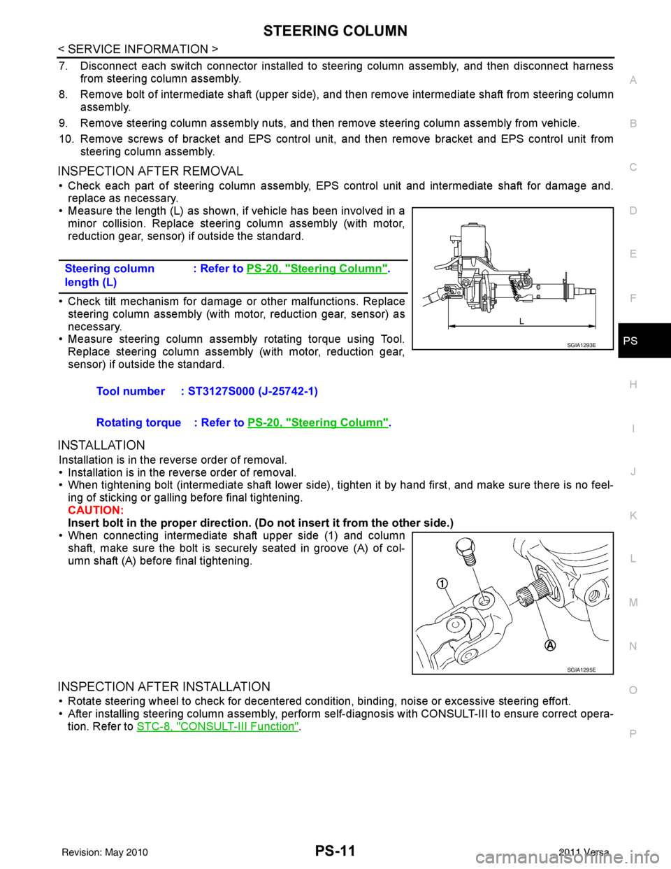
• Measure the length (L) as shown, if vehicle has been involved in a minor collision. Replace steering column assembly (with motor,
reduction gear, sensor) if outside the standard.
• Check tilt mechanism for damage or other malfunctions. Replace steering column assembly (with motor, reduction gear, sensor) as
necessary.
• Measure steering column assembly rotating torque using Tool.
Replace steering column assembly (with motor, reduction gear,
sensor) if outside the standard.
INSTALLATION
Installation is in the reverse order of removal.
• Installation is in the reverse order of removal.
• When tightening bolt (intermediate shaft lower side), tight en it by hand first, and make sure there is no feel-
ing of sticking or galling before final tightening.
CAUTION:
Insert bolt in the proper direction. (D o not insert it from the other side.)
• When connecting intermediate shaft upper side (1) and column shaft, make sure the bolt is securely seated in groove (A) of col-
umn shaft (A) before final tightening.
INSPECTION AFTER INSTALLATION
• Rotate steering wheel to check for decentered condition, binding, noise or excessive steering effort.
• After installing steering column assembly, perform self-diagnosis with CONSULT-III to ensure correct opera-
tion. Refer to STC-8, "
CONSULT-III Function".
Steering column
length (L)
: Refer to
PS-20, "
Steering Column".
Tool number : ST3127S000 (J-25742-1)
Rotating torque : Refer to PS-20, "
Steering Column".
SGIA1293E
SGIA1295E
Revision: May 2010 2011 Versa