2011 NISSAN LATIO glove box
[x] Cancel search: glove boxPage 3082 of 3787
LT-50
< SERVICE INFORMATION >
TURN SIGNAL AND HAZARD WARNING LAMPS
TURN SIGNAL AND HAZARD WARNING LAMPS
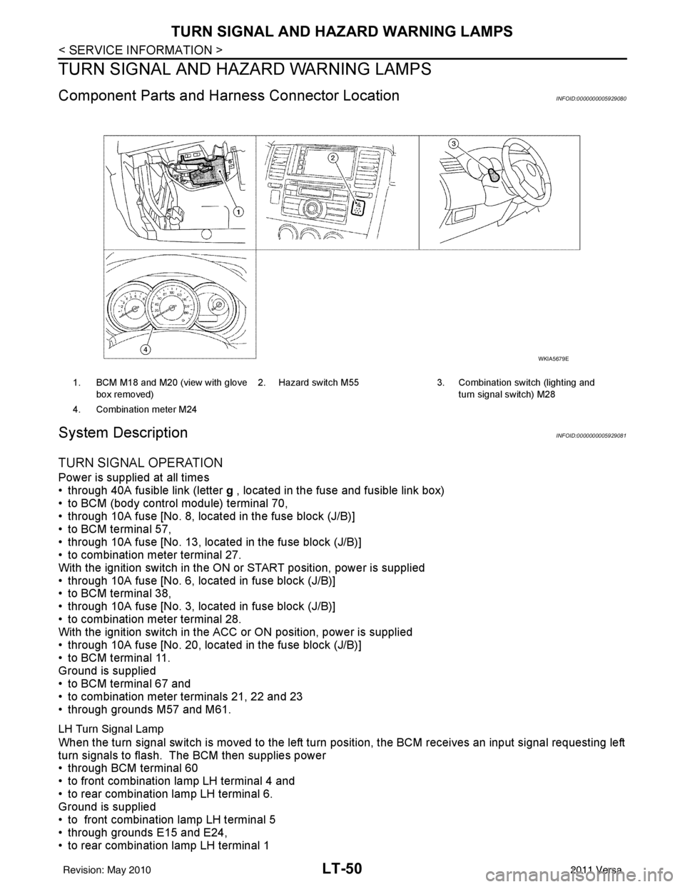
Component Parts and Harn ess Connector LocationINFOID:0000000005929080
System DescriptionINFOID:0000000005929081
TURN SIGNAL OPERATION
Power is supplied at all times
• through 40A fusible link (letter g , located in the fuse and fusible link box)
• to BCM (body control module) terminal 70,
• through 10A fuse [No. 8, located in the fuse block (J/B)]
• to BCM terminal 57,
• through 10A fuse [No. 13, located in the fuse block (J/B)]
• to combination meter terminal 27.
With the ignition switch in the ON or START position, power is supplied
• through 10A fuse [No. 6, located in fuse block (J/B)]
• to BCM terminal 38,
• through 10A fuse [No. 3, located in fuse block (J/B)]
• to combination meter terminal 28.
With the ignition switch in the ACC or ON position, power is supplied
• through 10A fuse [No. 20, located in the fuse block (J/B)]
• to BCM terminal 11.
Ground is supplied
• to BCM terminal 67 and
• to combination meter terminals 21, 22 and 23
• through grounds M57 and M61.
LH Turn Signal Lamp
When the turn signal switch is moved to the left turn position, the BCM receives an input signal requesting left
turn signals to flash. The BCM then supplies power
• through BCM terminal 60
• to front combination lamp LH terminal 4 and
• to rear combination lamp LH terminal 6.
Ground is supplied
• to front combination lamp LH terminal 5
• through grounds E15 and E24,
• to rear combination lamp LH terminal 1
1. BCM M18 and M20 (view with glove
box removed) 2. Hazard switch M55 3. Combination switch (lighting and
turn signal switch) M28
4. Combination meter M24
WKIA5679E
Revision: May 2010 2011 Versa
Page 3106 of 3787
LT-74
< SERVICE INFORMATION >
PARKING, LICENSE PLATE AND TAIL LAMPS
PARKING, LICENSE PLATE AND TAIL LAMPS
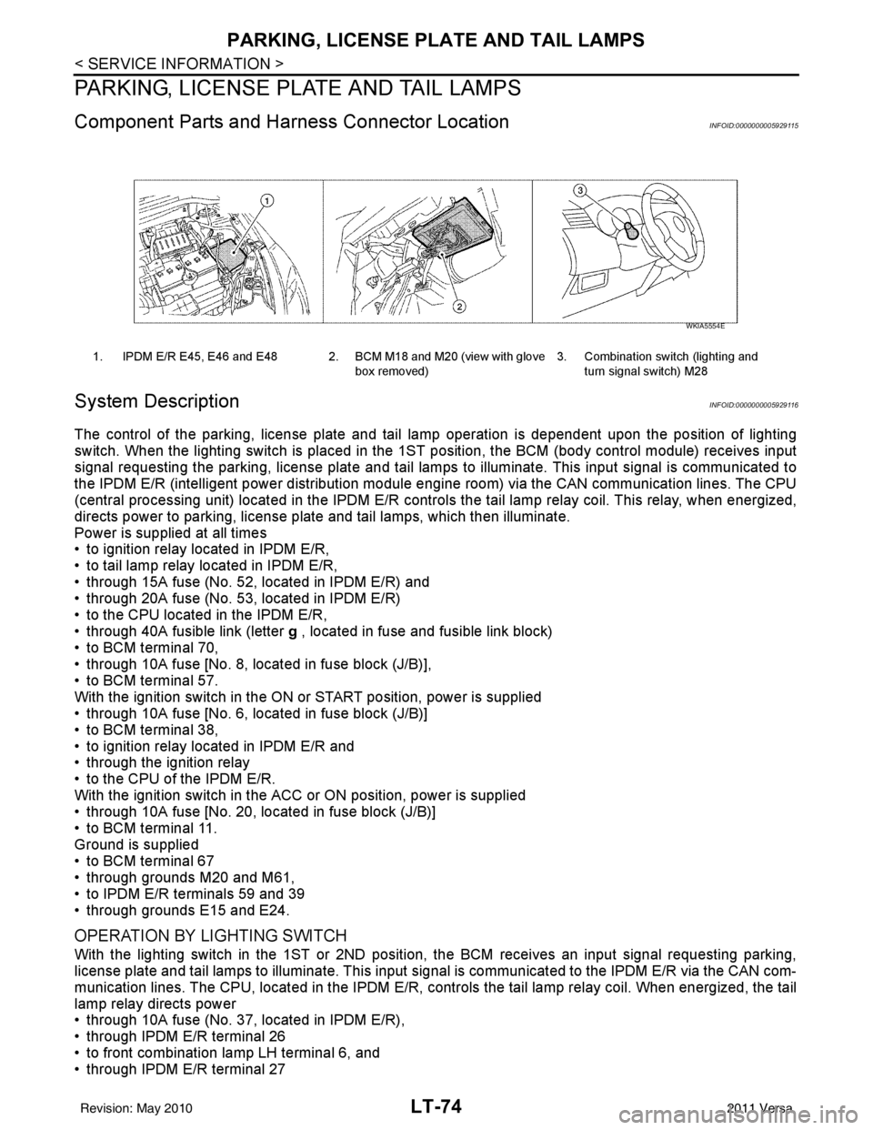
Component Parts and Harness Connector LocationINFOID:0000000005929115
System DescriptionINFOID:0000000005929116
The control of the parking, license plate and tail lamp operation is dependent upon the position of lighting
switch. When the lighting switch is placed in the 1ST position, the BCM (body cont rol module) receives input
signal requesting the parking, license plate and tail lamps to illuminate. This input signal is communicated to
the IPDM E/R (intelligent power distribution module engine room) via the CAN communication lines. The CPU
(central processing unit) located in the IPDM E/R contro ls the tail lamp relay coil. This relay, when energized,
directs power to parking, license plate and tail lamps, which then illuminate.
Power is supplied at all times
• to ignition relay located in IPDM E/R,
• to tail lamp relay located in IPDM E/R,
• through 15A fuse (No. 52, located in IPDM E/R) and
• through 20A fuse (No. 53, located in IPDM E/R)
• to the CPU located in the IPDM E/R,
• through 40A fusible link (letter g , located in fuse and fusible link block)
• to BCM terminal 70,
• through 10A fuse [No. 8, located in fuse block (J/B)],
• to BCM terminal 57.
With the ignition switch in the ON or START position, power is supplied
• through 10A fuse [No. 6, located in fuse block (J/B)]
• to BCM terminal 38,
• to ignition relay located in IPDM E/R and
• through the ignition relay
• to the CPU of the IPDM E/R.
With the ignition switch in the ACC or ON position, power is supplied
• through 10A fuse [No. 20, located in fuse block (J/B)]
• to BCM terminal 11.
Ground is supplied
• to BCM terminal 67
• through grounds M20 and M61,
• to IPDM E/R terminals 59 and 39
• through grounds E15 and E24.
OPERATION BY LIGHTING SWITCH
With the lighting switch in the 1ST or 2ND position, the BCM receives an input signal requesting parking,
license plate and tail lamps to illuminate. This input signal is communicated to the IPDM E/R via the CAN com-
munication lines. The CPU, located in the IPDM E/R, controls the tail lamp relay coil. When energized, the tail
lamp relay directs power
• through 10A fuse (No. 37, located in IPDM E/R),
• through IPDM E/R terminal 26
• to front combination lamp LH terminal 6, and
• through IPDM E/R terminal 27
1. IPDM E/R E45, E46 and E48 2. BCM M18 and M20 (view with glove
box removed)3. Combination switch (lighting and
turn signal switch) M28
WKIA5554E
Revision: May 2010 2011 Versa
Page 3125 of 3787
INTERIOR ROOM LAMPLT-93
< SERVICE INFORMATION >
C
DE
F
G H
I
J
L
M A
B
LT
N
O P
INTERIOR ROOM LAMP
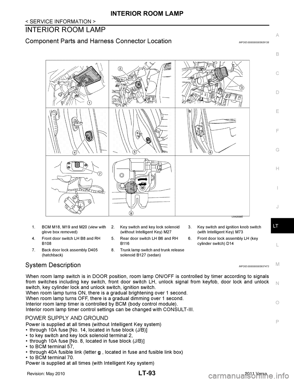
Component Parts and Har ness Connector LocationINFOID:0000000005929138
System DescriptionINFOID:0000000005937473
When room lamp switch is in DOOR position, room la mp ON/OFF is controlled by timer according to signals
from switches including key switch, front door switch LH, unlock signal from keyfob, door lock and unlock
switch, key cylinder lock and unlock switch, ignition switch.
When room lamp turns ON, there is a gradual brightening over 1 second.
When room lamp turns OFF, there is a gradual dimming over 1 second.
Interior room lamp timer is controlled by BCM (body control module).
Interior room lamp timer control settings can be changed with CONSULT-III.
POWER SUPPLY AND GROUND
Power is supplied at all times (without Intelligent Key system)
• through 10A fuse [No. 14, located in fuse block (J/B)]
• to key switch and key lock solenoid terminal 2,
• through 10A fuse [No. 8, located in fuse block (J/B)]
• to BCM terminal 57,
• through 40A fusible link (letter g , located in fuse and fusible link box)
• to BCM terminal 70.
Power is supplied at all times (with Intelligent Key system)
1. BCM M18, M19 and M20 (view with
glove box removed) 2. Key switch and key lock solenoid
(without Intelligent Key) M27 3. Key switch and ignition knob switch
(with Intelligent Key) M73
4. Front door switch LH B8 and RH B108 5. Rear door switch LH B6 and RH
B116 6. Front door lock assembly LH (key
cylinder switch) D14
7. Back door lock assembly D405 (hatchback) 8. Trunk lamp switch and trunk release
solenoid B127 (sedan)
LIIA2936E
Revision: May 2010 2011 Versa
Page 3372 of 3787
MTC-56
< SERVICE INFORMATION >
CONTROLLER
CONTROLLER
Removal and InstallationINFOID:0000000005930857
REMOVAL
1. Remove instrument finisher E. Refer to IP-11, "Component Parts" .
2. Remove instrument finisher D. Refer to IP-11, "
Component Parts" .
3. Remove cluster lid C. Refer to IP-11, "
Component Parts" .
4. Remove intake door lever knob. Refer to MTC-57, "
Disassembly and Assembly" .
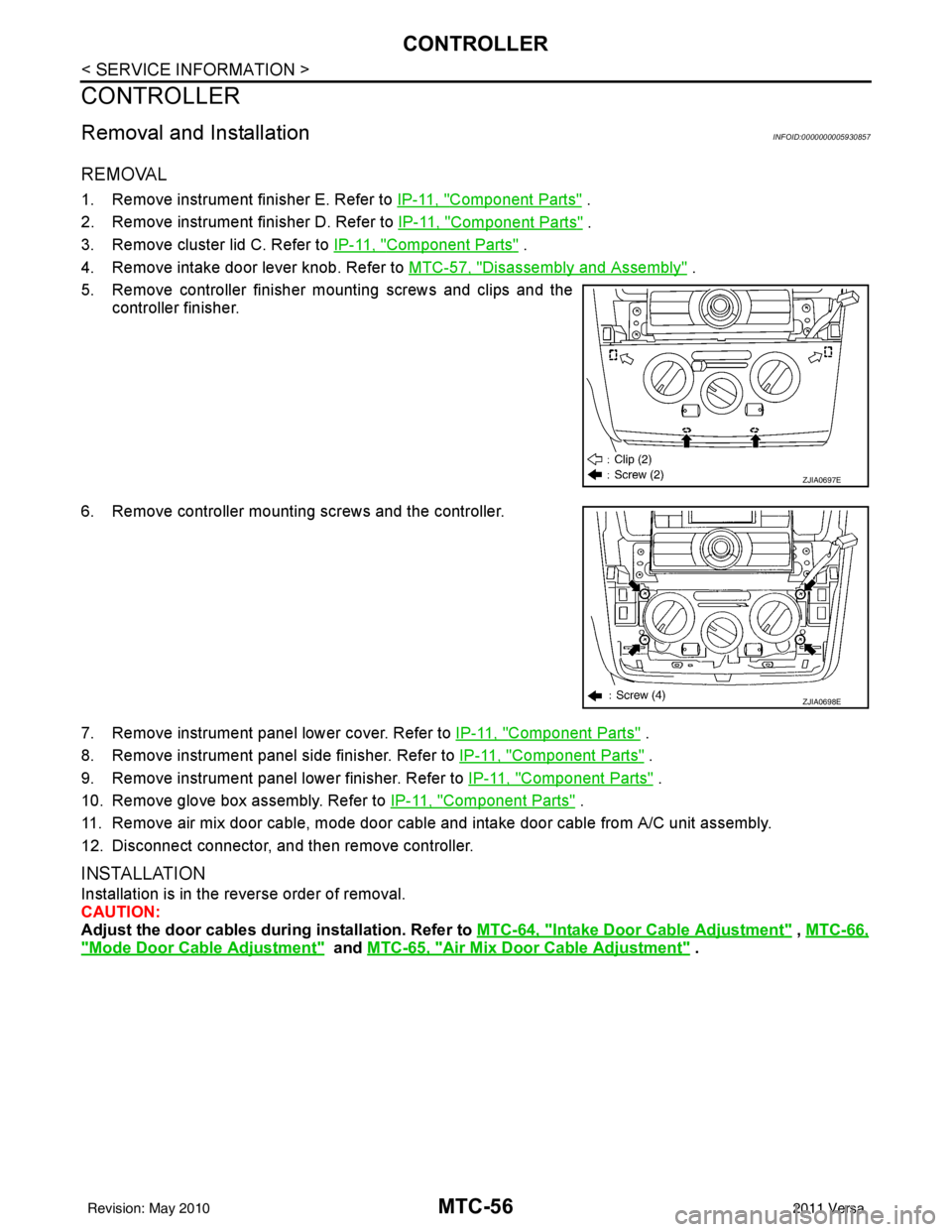
5. Remove controller finisher mounting screws and clips and the controller finisher.
6. Remove controller mounting screws and the controller.
7. Remove instrument panel lower cover. Refer to IP-11, "
Component Parts" .
8. Remove instrument panel side finisher. Refer to IP-11, "
Component Parts" .
9. Remove instrument panel lower finisher. Refer to IP-11, "
Component Parts" .
10. Remove glove box assembly. Refer to IP-11, "
Component Parts" .
11. Remove air mix door cable, mode door cable and intake door cable from A/C unit assembly.
12. Disconnect connector, and then remove controller.
INSTALLATION
Installation is in the reverse order of removal.
CAUTION:
Adjust the door cables duri ng installation. Refer to MTC-64, "
Intake Door Cable Adjustment" , MTC-66,
"Mode Door Cable Adjustment" and MTC-65, "Air Mix Door Cable Adjustment" .
ZJIA0697E
ZJIA0698E
Revision: May 2010 2011 Versa
Page 3382 of 3787
MTC-66
< SERVICE INFORMATION >
MODE DOOR
MODE DOOR
Mode Door Cable AdjustmentINFOID:0000000005930865
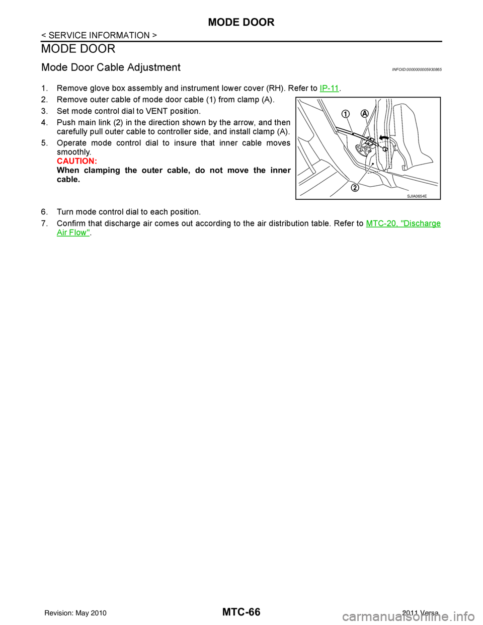
1. Remove glove box assembly and instrument lower cover (RH). Refer to IP-11.
2. Remove outer cable of mode door cable (1) from clamp (A).
3. Set mode control dial to VENT position.
4. Push main link (2) in the direction shown by the arrow, and then carefully pull outer cable to controller side, and install clamp (A).
5. Operate mode control dial to insure that inner cable moves smoothly.
CAUTION:
When clamping the outer cable, do not move the inner
cable.
6. Turn mode control dial to each position.
7. Confirm that discharge air comes out according to the air distribution table. Refer to MTC-20, "
Discharge
Air Flow".
SJIA0654E
Revision: May 2010 2011 Versa
Page 3534 of 3787
TROUBLE DIAGNOSISRF-11
< FUNCTION DIAGNOSIS >
C
DE
F
G H
J
K L
M A
B
RF
N
O P
FUNCTION DIAGNOSIS
TROUBLE DIAGNOSIS
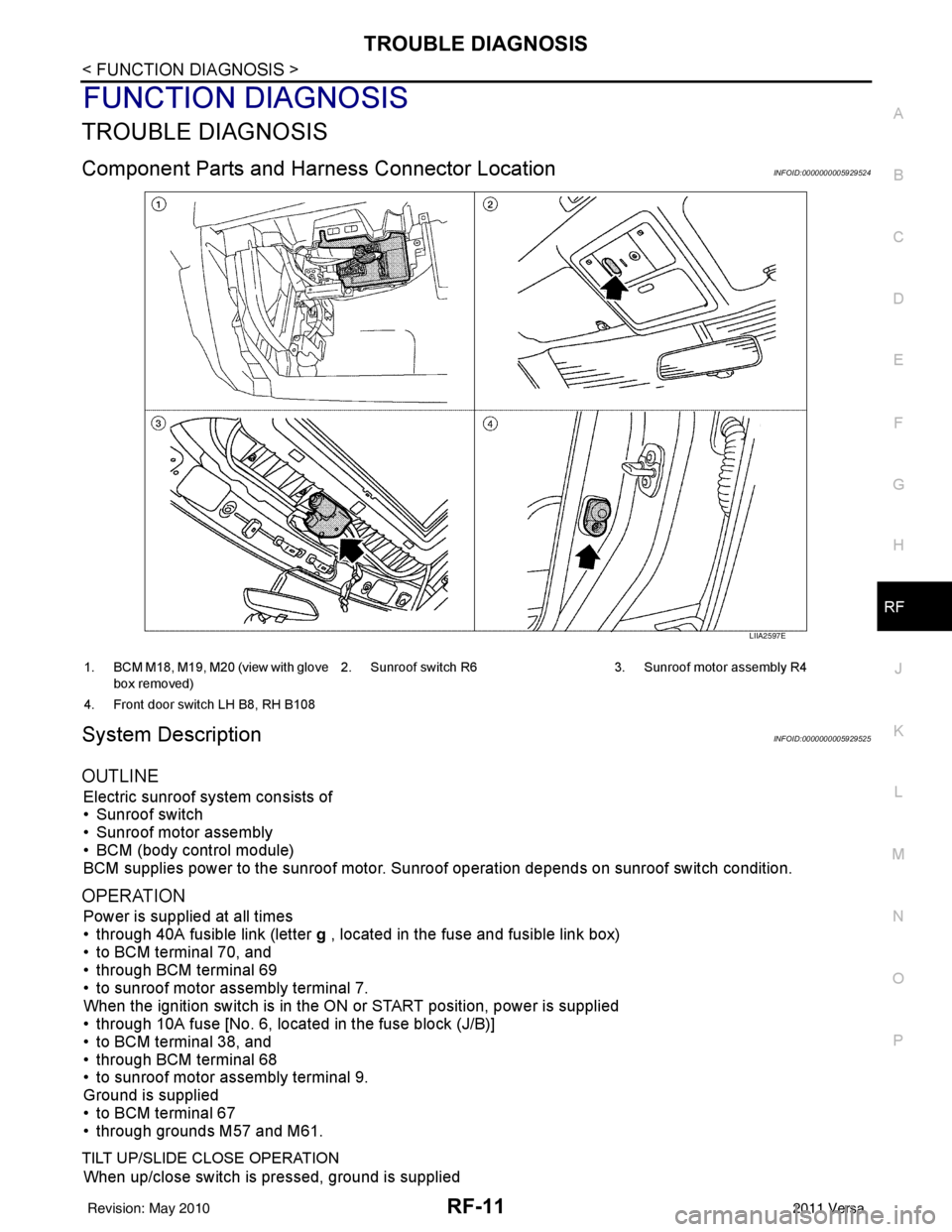
Component Parts and Har ness Connector LocationINFOID:0000000005929524
System DescriptionINFOID:0000000005929525
OUTLINE
Electric sunroof system consists of
• Sunroof switch
• Sunroof motor assembly
• BCM (body control module)
BCM supplies power to the sunroof motor. S unroof operation depends on sunroof switch condition.
OPERATION
Power is supplied at all times
• through 40A fusible link (letter g , located in the fuse and fusible link box)
• to BCM terminal 70, and
• through BCM terminal 69
• to sunroof motor assembly terminal 7.
When the ignition switch is in the ON or START position, power is supplied
• through 10A fuse [No. 6, located in the fuse block (J/B)]
• to BCM terminal 38, and
• through BCM terminal 68
• to sunroof motor assembly terminal 9.
Ground is supplied
• to BCM terminal 67
• through grounds M57 and M61.
TILT UP/SLIDE CLOSE OPERATION
When up/close switch is pressed, ground is supplied
LIIA2597E
1. BCM M18, M19, M20 (view with glove
box removed) 2. Sunroof switch R6 3. Sunroof motor assembly R4
4. Front door switch LH B8, RH B108
Revision: May 2010 2011 Versa
Page 3727 of 3787
TIRE PRESSURE MONITORING SYSTEMWT-9
< SERVICE INFORMATION >
C
DF
G H
I
J
K L
M A
B
WT
N
O P
TIRE PRESSURE MO NITORING SYSTEM
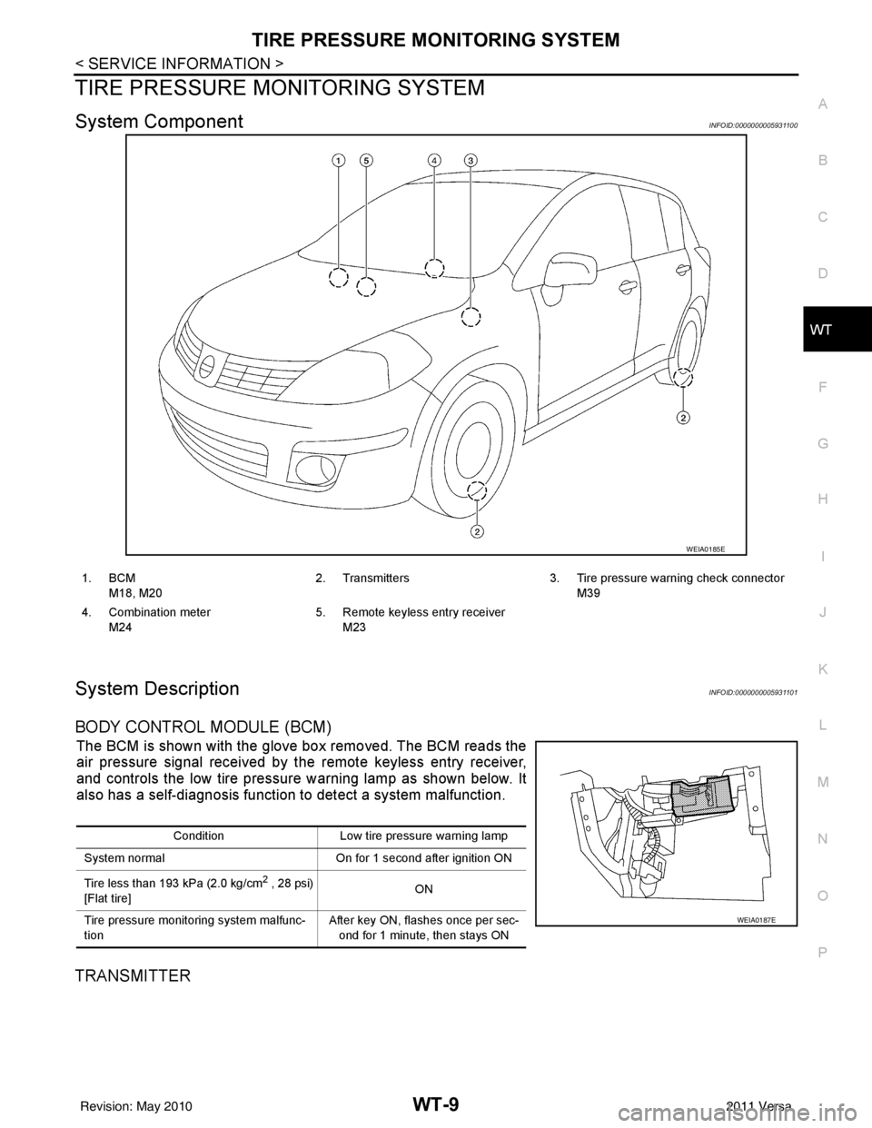
System ComponentINFOID:0000000005931100
System DescriptionINFOID:0000000005931101
BODY CONTROL MODULE (BCM)
The BCM is shown with the glove box removed. The BCM reads the
air pressure signal received by the remote keyless entry receiver,
and controls the low tire pressure warning lamp as shown below. It
also has a self-diagnosis function to detect a system malfunction.
TRANSMITTER
WEIA0185E
1. BCM
M18, M20 2. Transmitters 3. Tire pressure warning check connector
M39
4. Combination meter M24 5. Remote keyless entry receiver
M23
Condition Low tire pressure warning lamp
System normal On for 1 second after ignition ON
Tire less than 193 kPa (2.0 kg/cm
2 , 28 psi)
[Flat tire] ON
Tire pressure monitoring system malfunc-
tion After key ON, flashes once per sec-
ond for 1 minute, then stays ON
WEIA0187E
Revision: May 2010 2011 Versa
Page 3728 of 3787
WT-10
< SERVICE INFORMATION >
TIRE PRESSURE MONITORING SYSTEM
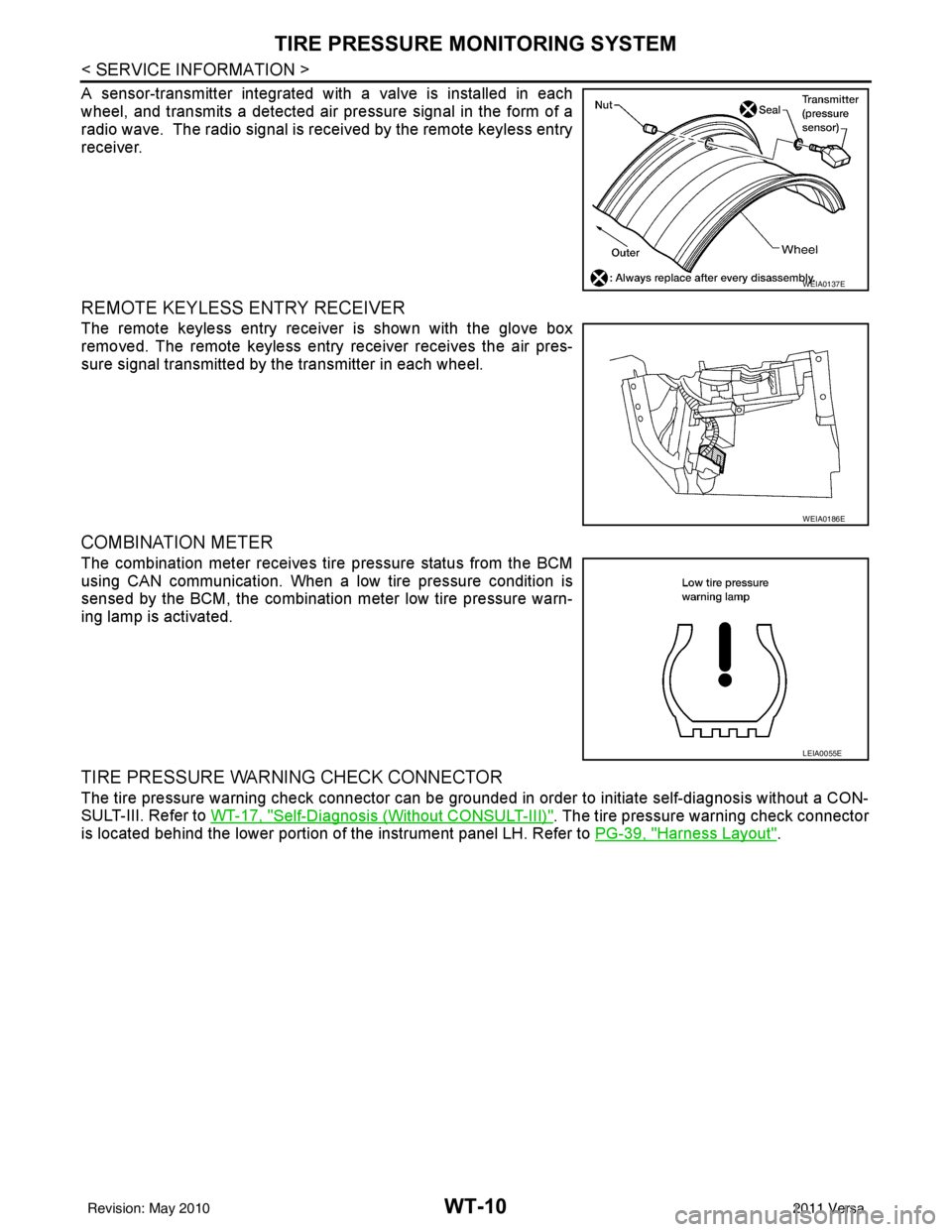
A sensor-transmitter integrated with a valve is installed in each
wheel, and transmits a detected air pressure signal in the form of a
radio wave. The radio signal is received by the remote keyless entry
receiver.
REMOTE KEYLESS ENTRY RECEIVER
The remote keyless entry receiver is shown with the glove box
removed. The remote keyless entry receiver receives the air pres-
sure signal transmitted by the transmitter in each wheel.
COMBINATION METER
The combination meter receives tire pressure status from the BCM
using CAN communication. When a low tire pressure condition is
sensed by the BCM, the combination meter low tire pressure warn-
ing lamp is activated.
TIRE PRESSURE WARNING CHECK CONNECTOR
The tire pressure warning check connector can be grounded in order to initiate self-diagnosis without a CON-
SULT-III. Refer to WT-17, "
Self-Diagnosis (Without CONSULT-III)". The tire pressure warning check connector
is located behind the lower portion of the instrument panel LH. Refer to PG-39, "
Harness Layout".
WEIA0137E
WEIA0186E
LEIA0055E
Revision: May 2010 2011 Versa