2011 NISSAN LATIO clutch
[x] Cancel search: clutchPage 3399 of 3787
REFRIGERANT LINESMTC-83
< SERVICE INFORMATION >
C
DE
F
G H
I
K L
M A
B
MTC
N
O P
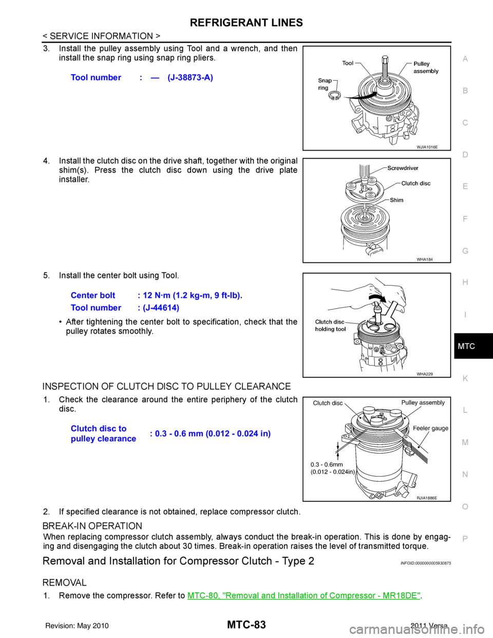
3. Install the pulley assembly using Tool and a wrench, and then install the snap ring using snap ring pliers.
4. Install the clutch disc on the drive shaft, together with the original shim(s). Press the clutch disc down using the drive plate
installer.
5. Install the center bolt using Tool. • After tightening the center bolt to specification, check that thepulley rotates smoothly.
INSPECTION OF CLUTCH DISC TO PULLEY CLEARANCE
1. Check the clearance around the entire periphery of the clutch
disc.
2. If specified clearance is not obt ained, replace compressor clutch.
BREAK-IN OPERATION
When replacing compressor clutch assembly, always conduct the break-in operation. This is done by engag-
ing and disengaging the clutch about 30 times. Break-in operation raises the level of transmitted torque.
Removal and Installation for Compressor Clutch - Type 2INFOID:0000000005930875
REMOVAL
1. Remove the compressor. Refer to MTC-80, "Removal and Installation of Compressor - MR18DE".
Tool number : — (J-38873-A)
WJIA1016E
WHA184
Center bolt : 12 N·m (1.2 kg-m, 9 ft-lb).
Tool number : (J-44614)
WHA229
Clutch disc to
pulley clearance
: 0.3 - 0.6 mm (0.012 - 0.024 in)
RJIA1886E
Revision: May 2010
2011 Versa
Page 3400 of 3787
MTC-84
< SERVICE INFORMATION >
REFRIGERANT LINES
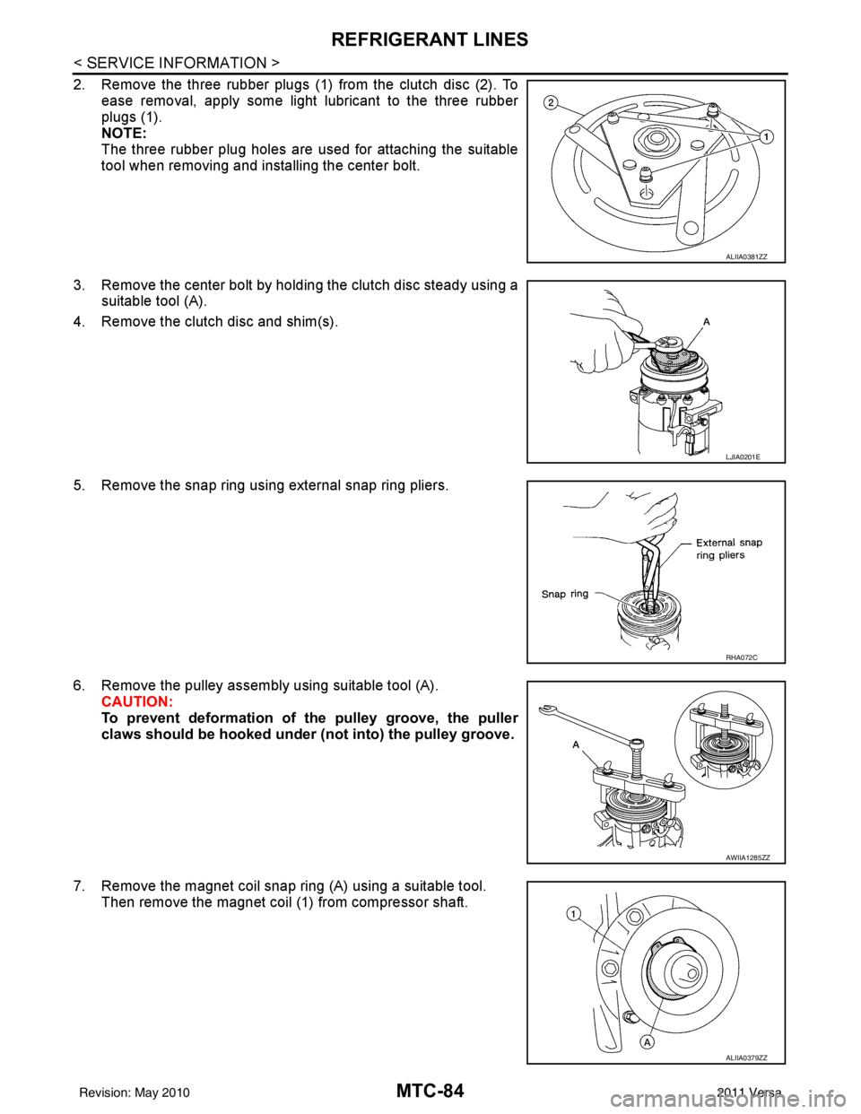
2. Remove the three rubber plugs (1) from the clutch disc (2). Toease removal, apply some light lubricant to the three rubber
plugs (1).
NOTE:
The three rubber plug holes are used for attaching the suitable
tool when removing and installing the center bolt.
3. Remove the center bolt by holding the clutch disc steady using a suitable tool (A).
4. Remove the clutch disc and shim(s).
5. Remove the snap ring using external snap ring pliers.
6. Remove the pulley assembly using suitable tool (A). CAUTION:
To prevent deformation of th e pulley groove, the puller
claws should be ho oked under (not into) the pulley groove.
7. Remove the magnet coil snap ring (A) using a suitable tool. Then remove the magnet coil (1) from compressor shaft.
ALIIA0381ZZ
LJIA0201E
RHA072C
AWIIA1285ZZ
ALIIA0379ZZ
Revision: May 2010 2011 Versa
Page 3401 of 3787
REFRIGERANT LINESMTC-85
< SERVICE INFORMATION >
C
DE
F
G H
I
K L
M A
B
MTC
N
O P
INSPECTION AFTER REMOVAL
Clutch Disc
If the contact surface shows signs of damage due to excessive heat, replace clutch disc and pulley.
Pulley
Check the appearance of the pulley assembly. If the cont act surface of the pulley shows signs of excessive
grooving, replace the clutch disc and pulley. The c ontact surfaces of the pulley assembly should be cleaned
with a suitable solvent before installation.
Coil
Check the magnet coil for a loose connection or cracked insulation.
INSTALLATION
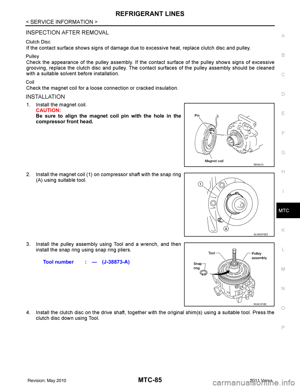
1. Install the magnet coil. CAUTION:
Be sure to align the magnet coil pin with the hole in the
compressor front head.
2. Install the magnet coil (1) on compressor shaft with the snap ring (A) using suitable tool.
3. Install the pulley assembly using Tool and a wrench, and then install the snap ring using snap ring pliers.
4. Install the clutch disc on the drive shaft, together with the original shim(s) using a suitable tool. Press the
clutch disc down using Tool.
WHA213
ALIIA0379ZZ
Tool number : — (J-38873-A)
WJIA1016E
Revision: May 2010 2011 Versa
Page 3402 of 3787
MTC-86
< SERVICE INFORMATION >
REFRIGERANT LINES
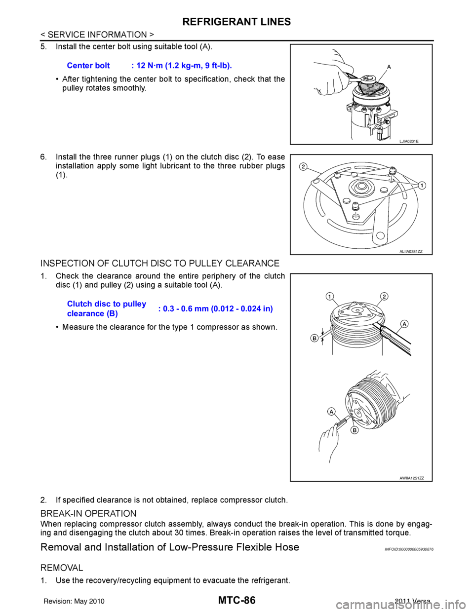
5. Install the center bolt using suitable tool (A).• After tightening the center bolt to specification, check that the
pulley rotates smoothly.
6. Install the three runner plugs (1) on the clutch disc (2). To ease installation apply some light lubricant to the three rubber plugs
(1).
INSPECTION OF CLUTCH DISC TO PULLEY CLEARANCE
1. Check the clearance around the entire periphery of the clutchdisc (1) and pulley (2) using a suitable tool (A).
• Measure the clearance for the type 1 compressor as shown.
2. If specified clearance is not obtained, replace compressor clutch.
BREAK-IN OPERATION
When replacing compressor clutch assembly, always conduct the break-in operation. This is done by engag-
ing and disengaging the clutch about 30 times. Break-in operation raises the level of transmitted torque.
Removal and Installation of Low-Pressure Flexible HoseINFOID:0000000005930876
REMOVAL
1. Use the recovery/recycling equipment to evacuate the refrigerant.Center bolt : 12 N·m (1.2 kg-m, 9 ft-lb).
LJIA0201E
ALIIA0381ZZ
Clutch disc to pulley
clearance (B)
: 0.3 - 0.6 mm (0.012 - 0.024 in)
AWIIA1251ZZ
Revision: May 2010
2011 Versa
Page 3437 of 3787

IPDM E/R (INTELLIGENT POWER DISTRIBUTION MODULE ENGINE ROOM)
PG-17
< SERVICE INFORMATION >
C
D E
F
G H
I
J
L
M A
B
PG
N
O P
IPDM E/R (INTELLIGENT POWER DISTRIBUTION MODULE ENGINE
ROOM)
System DescriptionINFOID:0000000005928343
• IPDM E/R (Intelligent Power Distribution Module Engi ne Room) integrates the relay box and fuse block
which were originally placed in engine compartment. It controls integrated relays via IPDM E/R control cir-
cuits.
• IPDM E/R-integrated control circuits perform ON-OFF operation of relays, CAN communication control, oil pressure switch signal reception, etc.
• It controls operation of each electrical co mponent via ECM, BCM and CAN communication lines.
CAUTION:
None of the IPDM E/R integr ated relays can be removed.
SYSTEMS CONTROLLED BY IPDM E/R
1. Lamp control
Using CAN communication lines, it receives signals from the BCM and controls the following lamps:
• Headlamps (High, Low)
• Parking lamps
• Tail and license plate lamps
• Front fog lamps
2. Wiper control Using CAN communication lines, it receives signals from the BCM and controls the front wipers.
3. Rear window defogger relay control Using CAN communication lines, it receives signals from the BCM and controls the rear window defogger
relay.
4. A/C compressor control Using CAN communication lines, it receives signal s from the ECM and controls the A/C compressor
(magnet clutch).
5. Starter control Using CAN communication lines, it receives signals from the BCM and controls the starter relay.
6. Cooling fan control Using CAN communication lines, it receives signals from the ECM and controls the cooling fan relays.
7. Horn control Using CAN communication lines, it receives signals from the BCM and controls the horn relay.
8. Daytime light system control (Canada only) Using CAN communication lines, it receives signals from the BCM and controls the daytime light relay.
CAN COMMUNICATION LINE CONTROL
With CAN communication, by connecting each control unit using two communication lines (CAN L-line, CAN
H-line), it is possible to transmit a maximum amount of information with minimum wiring. Each control unit can
transmit and receive data, and reads necessary information only.
1. Fail-safe control • When CAN communication with other control units is impossible, IPDM E/R performs fail-safe control.
After CAN communication returns to normal operation, it also returns to normal control.
• Operation of control parts by IPDM E/ R during fail-safe mode is as follows:
Controlled system Fail-safe mode
Headlamp • With the ignition switch ON, headlamp low relay is ON, headlamp high relays are OFF, and
daytime light system (Canada only) is OFF.
• With the ignition switch OFF, the headlamp relays are OFF.
Tail, license plate and parking lamps • With the ignition switch ON, the tail lamp relay is ON. • With the ignition switch OFF, the tail lamp relay is OFF.
Cooling fan • With the ignition switch ON, cooling fan relay-1, relay-2, and relay-3 are ON.
• With the ignition switch OFF, all cooling fan relays are OFF.
Front wiper Until the ignition switch is turned off, the front wiper relays remain in the same status they
were in just before fail
−safe control was initiated.
Revision: May 2010 2011 Versa
Page 3440 of 3787

PG-20
< SERVICE INFORMATION >
IPDM E/R (INTELLIGENT POWER DISTRIBUTION MODULE ENGINE ROOM)
*1 Perform monitoring of IPDM E/R data with the ignition switch ON. When the ignition switch is in ACC position, display may no t be cor-
rect.
*2 This item is displayed, but does not function.
CAN DIAG SUPPORT MNTR
Refer to LAN-9, "Description" .
ACTIVE TEST
Display Item List
Auto Active TestINFOID:0000000005928347
DESCRIPTION
• In auto active test mode, operation inspection can be performed when IPDM E/R sends a drive signal to the
following systems:
- Rear window defogger
- Front wipers
- Tail, license and parking lamps
- Daytime lamp system (Canada only)
- Front fog lamps
- Headlamps (High, Low)
- A/C compressor (magnet clutch)
- Cooling fan
OPERATION PROCEDURE
1. Close hood and front door RH, and lift wiper arms away from windshield (to prevent glass damage by wiper operation).
NOTE:
When auto active test is performed with hood opened, sprinkle water on windshield beforehand.
2. Turn ignition switch OFF.
3. Turn ignition switch ON and, within 20 seconds, pres s front door switch LH 10 times. Then turn ignition
switch OFF.
4. Turn ignition switch ON within 10 seconds after ignition switch OFF.
5. When auto active test mode is actuated, horn chirps once.
6. After a series of operations is repeated three times, auto active test is completed.
Theft warning
horn request THFT HRN REQ ON/OFF
XX Signal status input from BCM
Horn chirp HORN CHIRP ON/OFF XX Output status of IPDM E/R
Daytime light re-
quest DTRL REQ ON/OFF
XX Signal status input from BCM
Item name
CONSULT-III
screen display Display or unit Monitor item selection
Description
ALL
SIGNALS MAIN
SIGNALS SELECTION
FROM MENU
Test name CONSULT-III screen display Description
Head, tail, fog lamp output EXTERNAL LAMPS With a certain ON-OFF operation (OFF, TAIL, LO, HI, FOG), the front
fog lamp, headlamp low, headlamp high RH, headlamp high LH, and
tail lamp relays can be operated.
Rear defogger output REAR DEFOGGER With a certain ON-OFF operation, the rear defogger relay can be oper-
ated.
Front wiper (HI, LO) output FRONT WIPER With a certain operation (OFF, HI ON, LO ON), the front wiper relays
(Lo, Hi) can be operated.
Cooling fan output MOTOR FAN With a certain operation (1, 2, 3, 4), the cooling fan relays can be oper-
ated.
Horn output HORN With a certain ON-OFF operation, the horn relay can be operated.
Revision: May 2010 2011 Versa
Page 3441 of 3787
IPDM E/R (INTELLIGENT POWER DISTRIBUTION MODULE ENGINE ROOM)
PG-21
< SERVICE INFORMATION >
C
D E
F
G H
I
J
L
M A
B
PG
N
O P
NOTE:
When auto active test mode has to be cancelled halfway, turn ignition switch OFF.
CAUTION:
Be sure to perform BL-44, "
Door Switch Check (Hatchback)" or BL-47, "Door Switch Check
(Sedan)" when the auto active test cannot be performed.
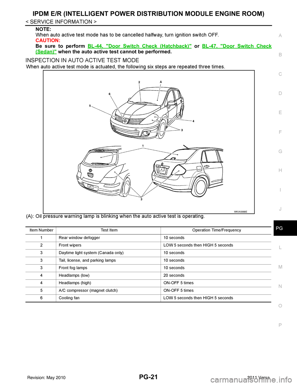
INSPECTION IN AUTO ACTIVE TEST MODE
When auto active test mode is actuated, the following six steps are repeated three times.
(A): Oil pressure warning lamp is blinking when the auto active test is operating.
WKIA5988E
Item Number Test Item Operation Time/Frequency
1 Rear window defogger 10 seconds
2 Front wipers LOW 5 seconds then HIGH 5 seconds
3 Daytime light system (Canada only) 10 seconds
3 Tail, license, and parking lamps 10 seconds
3 Front fog lamps 10 seconds
4 Headlamps (low) 20 seconds
4 Headlamps (high) ON-OFF 5 times
5 A/C compressor (magnet clutch) ON-OFF 5 times
6 Cooling fan LOW 5 seconds then HIGH 5 seconds
Revision: May 2010 2011 Versa
Page 3442 of 3787
PG-22
< SERVICE INFORMATION >
IPDM E/R (INTELLIGENT POWER DISTRIBUTION MODULE ENGINE ROOM)
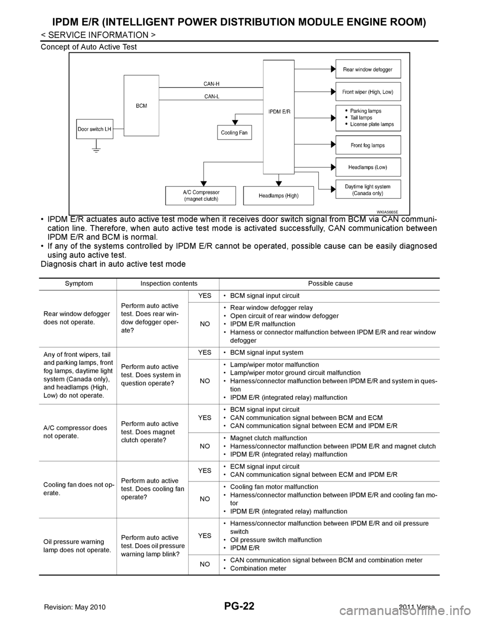
Concept of Auto Active Test
• IPDM E/R actuates auto active test mode when it re ceives door switch signal from BCM via CAN communi-
cation line. Therefore, when auto active test mode is activated successfully, CAN communication between
IPDM E/R and BCM is normal.
• If any of the systems controll ed by IPDM E/R cannot be operated, possible cause can be easily diagnosed
using auto active test.
Diagnosis chart in auto active test mode
WKIA5665E
Symptom Inspection contents Possible cause
Rear window defogger
does not operate. Perform auto active
test. Does rear win-
dow defogger oper-
ate?YES • BCM signal input circuit
NO • Rear window defogger relay
• Open circuit of rear window defogger
•IPDM E/R malfunction
• Harness or connector malfunction between IPDM E/R and rear window
defogger
Any of front wipers, tail
and parking lamps, front
fog lamps, daytime light
system (Canada only),
and headlamps (High,
Low) do not operate. Perform auto active
test. Does system in
question operate?YES • BCM signal input system
NO • Lamp/wiper motor malfunction
• Lamp/wiper motor ground circuit malfunction
• Harness/connector malfunction between IPDM E/R and system in ques-
tion
• IPDM E/R (integrated relay) malfunction
A/C compressor does
not operate. Perform auto active
test. Does magnet
clutch operate?YES
• BCM signal input circuit
• CAN communication signal between BCM and ECM
• CAN communication signal between ECM and IPDM E/R
NO • Magnet clutch malfunction
• Harness/connector malfunction between IPDM E/R and magnet clutch
• IPDM E/R (integrated relay) malfunction
Cooling fan does not op-
erate. Perform auto active
test. Does cooling fan
operate?YES
• ECM signal input circuit
• CAN communication signal between ECM and IPDM E/R
NO • Cooling fan motor malfunction
• Harness/connector malfunction between IPDM E/R and cooling fan mo-
tor
• IPDM E/R (integrated relay) malfunction
Oil pressure warning
lamp does not operate. Perform auto active
test. Does oil pressure
warning lamp blink?YES
• Harness/connector malfunction between IPDM E/R and oil pressure
switch
• Oil pressure switch malfunction
•IPDM E/R
NO • CAN communication signal between BCM and combination meter
• Combination meter
Revision: May 2010
2011 Versa