2011 NISSAN LATIO service interval
[x] Cancel search: service intervalPage 3210 of 3787
![NISSAN LATIO 2011 Service Repair Manual CHASSIS AND BODY MAINTENANCEMA-39
< SERVICE INFORMATION >
C
DE
F
G H
I
J
K
M A
B
MA
N
O P
• : Vehicle front
• Radiator (2)
• CVT fluid cooler hose [inlet side (3)]
• Transaxle assembly (4)
2. NISSAN LATIO 2011 Service Repair Manual CHASSIS AND BODY MAINTENANCEMA-39
< SERVICE INFORMATION >
C
DE
F
G H
I
J
K
M A
B
MA
N
O P
• : Vehicle front
• Radiator (2)
• CVT fluid cooler hose [inlet side (3)]
• Transaxle assembly (4)
2.](/manual-img/5/57357/w960_57357-3209.png)
CHASSIS AND BODY MAINTENANCEMA-39
< SERVICE INFORMATION >
C
DE
F
G H
I
J
K
M A
B
MA
N
O P
• : Vehicle front
• Radiator (2)
• CVT fluid cooler hose [inlet side (3)]
• Transaxle assembly (4)
2. Drain CVT fluid from CVT fluid cooler hose [outlet side (1)] and refill with new specified NISSAN CVT fluid in the CVT fluid
charging pipe with the engine running at idle speed.
CAUTION:
Only use the specifi ed NISSAN CVT fluid.
3. Refill until new CVT fluid comes out from CVT fluid cooler hose [outlet side (1)]. NOTE:
About 30 to 50% extra fluid will be required for this procedure.
4. Check fluid level and condition. Refer to MA-37, "
CVT FLUID : Checking CVT Fluid".
CAUTION:
Delete CVT fluid deterioration date with CONSULT-III after changing CVT fluid. Refer to CVT-48,
"CONSULT-III Function (TRANSMISSION)".
CLUTCH FLUID
CLUTCH FLUID : Air Bleeding ProcedureINFOID:0000000005931169
CAUTION:
Do not spill clutch fluid onto painted surfaces. If it spills, wipe up immediately and wash the affected
area with water.
NOTE:
• Do not use a vacuum assist or any other type of power bleeder on this system. Use of a vacuum assist or power bleeder will not purge all the air from the system.
• Carefully monitor fluid level in reservoir tank during bleeding operation.
1. Fill master cylinder reservoir tank with new clutch fluid.
2. Connect a transparent vinyl tube and container to the bleeding connector (1) on the CSC.
3. Depress and release the clutch pedal slowly and fully 15 times at an interval of two to three seconds and release the clutch
pedal.
4. Push in the lock pin (1) of the bleeding connector (2), and maintain the position. • RS5F91R transaxle models
CAUTION:
Hold the lock pin in to preven t the bleeding connector from
separating when fluid pressure is applied.
Fluid capacity and grade: Refer to
MA-14, "
Fluids
and Lubricants".SCIA6088E
PCIB1494E
PCIB1495E
Revision: May 2010 2011 Versa
Page 3216 of 3787

CHASSIS AND BODY MAINTENANCEMA-45
< SERVICE INFORMATION >
C
DE
F
G H
I
J
K
M A
B
MA
N
O P
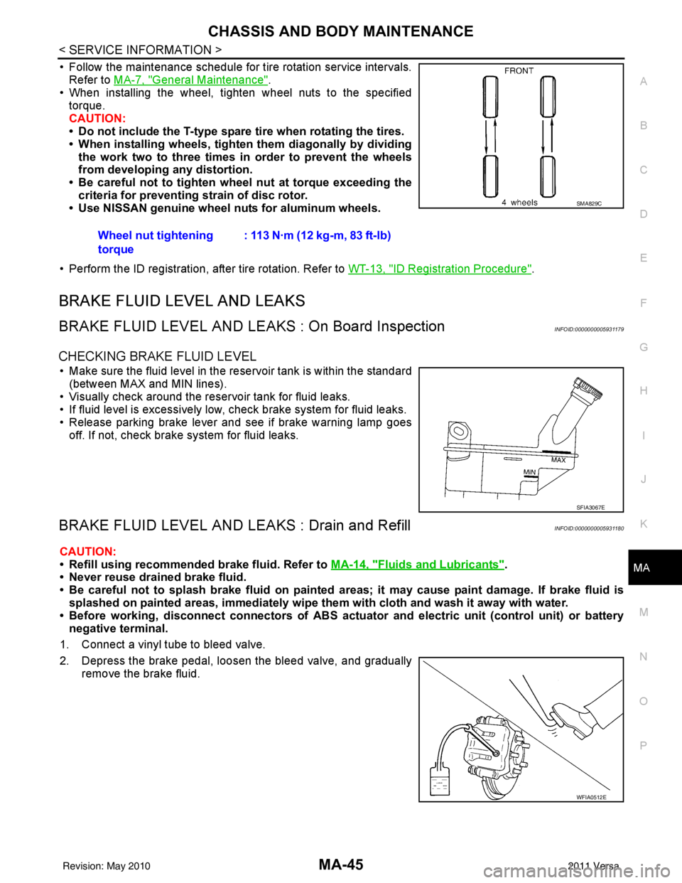
• Follow the maintenance schedule for tire rotation service intervals. Refer to MA-7, "
General Maintenance".
• When installing the wheel, tighten wheel nuts to the specified
torque.
CAUTION:
• Do not include the T-type spare tire when rotating the tires.
• When installing wheels, tighte n them diagonally by dividing
the work two to three times in order to prevent the wheels
from developing any distortion.
• Be careful not to tighten wh eel nut at torque exceeding the
criteria for preventing strain of disc rotor.
• Use NISSAN genuine wheel nuts for aluminum wheels.
• Perform the ID registration, after tire rotation. Refer to WT-13, "
ID Registration Procedure".
BRAKE FLUID LEVEL AND LEAKS
BRAKE FLUID LEVEL AND LEAKS : On Board InspectionINFOID:0000000005931179
CHECKING BRAKE FLUID LEVEL
• Make sure the fluid level in the reservoir tank is within the standard
(between MAX and MIN lines).
• Visually check around the reservoir tank for fluid leaks.
• If fluid level is excessively low, check brake system for fluid leaks.
• Release parking brake lever and see if brake warning lamp goes off. If not, check brake system for fluid leaks.
BRAKE FLUID LEVEL AND LEAKS : Drain and RefillINFOID:0000000005931180
CAUTION:
• Refill using recommended brake fluid. Refer to MA-14, "
Fluids and Lubricants".
• Never reuse drained brake fluid.
• Be careful not to splash brake fluid on painted areas; it may cause paint damage. If brake fluid is
splashed on painted areas, immediately wipe th em with cloth and wash it away with water.
• Before working, disconnect connect ors of ABS actuator and electric unit (control unit) or battery
negative terminal.
1. Connect a vinyl tube to bleed valve.
2. Depress the brake pedal, loosen the bleed valve, and gradually remove the brake fluid.Wheel nut tightening
torque
: 113 N·m (12 kg-m, 83 ft-lb)
SMA829C
SFIA3067E
WFIA0512E
Revision: May 2010
2011 Versa
Page 3726 of 3787

WT-8
< SERVICE INFORMATION >
ROAD WHEEL TIRE ASSEMBLY
4. If calculated balance weight value exceeds 50 g (1.76 oz), installtwo balance weight sheets in line with each other as shown.
CAUTION:
Do not install one balance weight sheet on top another.
5. Start balancer machine again.
6. Install balance weight on inner side of road wheel in the bal- ancer machine indication position (angle).
CAUTION:
Do not install more than two balance weights.
7. Start balancer machine. Make sure that inner and outer residual imbalance values are 5 g (0.17 oz) each or below.
8. If either residual imbalance value exceeds 5 g (0.17 oz), repeat installation procedures.
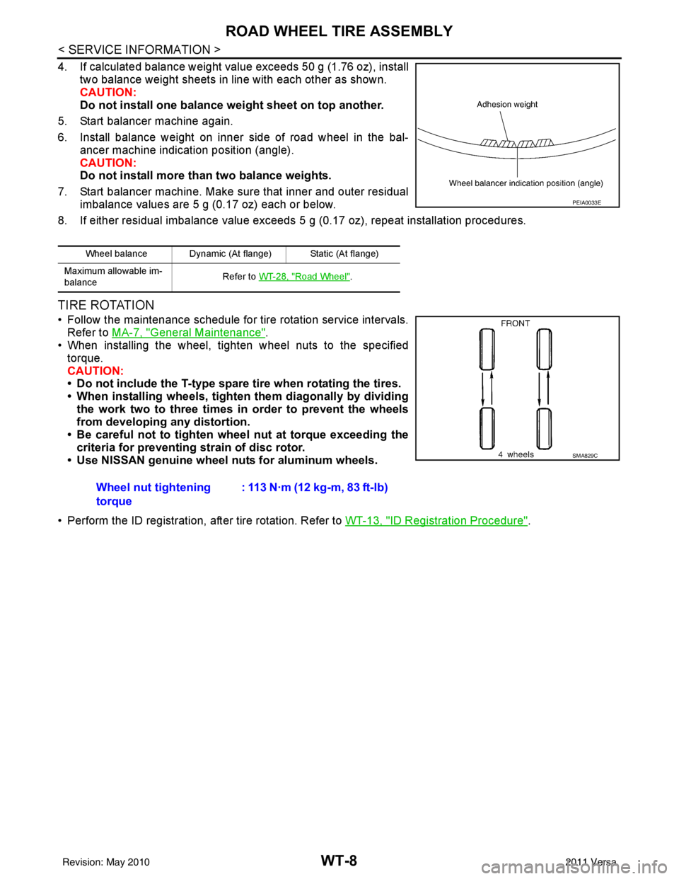
TIRE ROTATION
• Follow the maintenance schedule for tire rotation service intervals.
Refer to MA-7, "
General Maintenance".
• When installing the wheel, tighten wheel nuts to the specified
torque.
CAUTION:
• Do not include the T-type spare tire when rotating the tires.
• When installing wheels, tighten them diagonally by dividing
the work two to three times in order to prevent the wheels
from developing any distortion.
• Be careful not to tighten wheel nut at torque exceeding the criteria for preventing strain of disc rotor.
• Use NISSAN genuine wheel nuts for aluminum wheels.
• Perform the ID registration, after tire rotation. Refer to WT-13, "
ID Registration Procedure".
Wheel balance Dynamic (At flange) Static (At flange)
Maximum allowable im-
balance Refer to
WT-28, "
Road Wheel".
PEIA0033E
Wheel nut tightening
torque : 113 N·m (12 kg-m, 83 ft-lb)
SMA829C
Revision: May 2010
2011 Versa
Page 3752 of 3787

WW-6
< SERVICE INFORMATION >
FRONT WIPER AND WASHER SYSTEM
• to front wiper high relay (located in IPDM E/R), and
• to CPU (located in IPDM E/R),
• through 10A fuse [No. 6, located in fuse block (J/B)]
• to BCM terminal 38,
• through 15A fuse [No. 4, located in fuse block (J/B)]
• to combination switch (wiper switch) terminal 14.
Ground is supplied
• to IPDM E/R terminals 39 and 59, and
• to front wiper motor terminal 2
• through grounds E15 and E24
• to BCM terminal 67, and
• to combination switch (wiper switch) terminal 12
• through grounds M57 and M61.
LOW SPEED WIPER OPERATION
When the front combination switch (wiper switch) is in LO position, the BCM detects the low speed wiper ON
signal by means of the BCM combination switch (wiper switch) reading function.
The BCM sends a front wiper request signal (LO) through the CAN communication line
• from BCM terminals 39 and 40
• to IPDM E/R terminals 40 and 41.
When the IPDM E/R receives front wiper request signal (LO) , it turns ON front wiper relay, located in IPDM E/
R, power is supplied
• through IPDM E/R terminal 33 and front wiper high relay and front wiper relay
• to front wiper motor terminal 3.
Ground is supplied
• to front wiper motor terminal 2
• through grounds E15 and E24.
With power and ground is supplied, front wiper motor operates at low speed.
HIGH SPEED WIPER OPERATION
When the front combination switch (wiper switch) is in HI position, the BCM detects a high speed wiper ON
signal by means of the BCM combination switch (wiper switch) reading function.
The BCM sends a front wiper request signal (HI) through the CAN communication line
• from BCM terminals 39 and 40
• to IPDM E/R terminals 40 and 41.
When the IPDM E/R receives front wiper request signal (HI), it turns ON front wiper relay and front wiper high
relay, located in IPDM E/R, power is supplied
• through IPDM E/R terminal 32
• to front wiper motor terminal 5.
Ground is supplied
• to front wiper motor terminal 2
• through grounds E15 and E24.
With power and ground is supplied, front wiper motor operates at high speed.
INTERMITTENT OPERATION
Wiper intermittent operation delay interval is determined from the intermittent wiper dial position inputs. During
each intermittent operation delay interval, the BCM s ends a front wiper request signal to the IPDM E/R to
operate the wipers.
When the ignition switch is in the ON or START positi on, and the front combination switch (wiper switch) is
turned to the intermittent position, the BCM detects a fr ont wiper (intermittent) ON signal by means of the BCM
combination switch (wiper switch) reading function.
BCM then sends front wiper (intermittent) request signal through the CAN communication lines
• from BCM terminals 39 and 40
• to IPDM E/R terminals 40 and 41.
When BCM determines that combination switch (wiper swit ch) status is front wiper intermittent ON, it performs
the following operations.
• BCM detects ON/OFF status of intermittent wiper dial position
• BCM calculates operation interval from wiper dial position.
• BCM sends a front wiper request signal (INT) to IPDM E/R at calculated operation interval.
When IPDM E/R receives the front wiper request signal (INT), it supplies ground to energize the front wiper
relay. It then sends auto-stop signal to the BCM and conducts intermittent front wiper motor operation.
Revision: May 2010 2011 Versa