2011 NISSAN LATIO clutch
[x] Cancel search: clutchPage 2761 of 3787
SQUEAK AND RATTLE TROUBLE DIAGNOSESGW-7
< SERVICE INFORMATION >
C
DE
F
G H
J
K L
M A
B
GW
N
O P
If the noise can be duplicated easily during the test drive, to help identify the source of the noise, try to dupli-
cate the noise with the vehicle stopped by doing one or all of the following:
1) Close a door.
2) Tap or push/pull around the area where the noise appears to be coming from.
3) Rev the engine.
4) Use a floor jack to recreate vehicle “twist”.
5) At idle, apply engine load (electrical load, half- clutch on M/T model, drive position on A/T model).
6) Raise the vehicle on a hoist and hit a tire with a rubber hammer.
• Drive the vehicle and attempt to duplicate the conditions the customer states exist when the noise occurs.
• If it is difficult to duplicate the noise, drive the vehicle slowly on an undulating or rough road to stress the vehicle body.
CHECK RELATED SERVICE BULLETINS
After verifying the customer concern or symptom, check ASIST for Technical Service Bulletins (TSBs) related
to that concern or symptom.
If a TSB relates to the symptom, follow the procedure to repair the noise.
LOCATE THE NOISE AND IDENTIFY THE ROOT CAUSE
1. Narrow down the noise to a general area.To help pinpoint the source of the noise, use a listening tool (Chassis Ear: J-39570, Engine Ear: J-39565 and mechanic's stethoscope).
2. Narrow down the noise to a more specific area and identify the cause of the noise by:
• removing the components in the area that you suspect the noise is coming from. Do not use too much force when removing clips and fasteners, otherwise clips and fasteners can be broken
or lost during the repair, resulting in the creation of new noise.
• tapping or pushing/pulling the component that you suspect is causing the noise.
Do not tap or push/pull the component with excessive force, otherwise the noise will be eliminated only tem-
porarily.
• feeling for a vibration with your hand by touching the component(s) that you suspect is (are) causing the
noise.
• placing a piece of paper between components that you suspect are causing the noise.
• looking for loose components and contact marks. Refer to GW-8, "
Generic Squeak and Rattle Troubleshooting".
REPAIR THE CAUSE
• If the cause is a loose component, tighten the component securely.
• If the cause is insufficient clearance between components:
- separate components by repositioning or loos ening and retightening the component, if possible.
- insulate components with a suitable insulator such as urethane pads, foam blocks, felt cloth tape or urethane tape. A NISSAN Squeak and Rattle Kit (J-43980) is available through your authorized NISSAN Parts Depart-
ment.
CAUTION:
Do not use excessive force as many components are constructed of plastic and may be damaged.
Always check with the Parts Department for the latest parts information.
The following materials are contained in the NISSAN Squeak and Rattle Kit (J-43980). Each item can be
ordered separately as needed.
URETHANE PADS [1.5 mm (0.059 in) thick]
Insulates connectors, harness, etc.
76268-9E005: 100 ×135 mm (3.94 ×5.31 in)/76884-71L01: 60 ×85 mm (2.36× 3.35 in)/76884-71L02: 15× 25
mm (0.59 ×0.98 in)
INSULATOR (Foam blocks)
Insulates components from contact. Can be used to fill space behind a panel.
73982-9E000: 45 mm (1.77 in) thick, 50× 50 mm (1.97×1.97 in)/73982-50Y00: 10 mm (0.39 in) thick,
50× 50 mm (1.97 ×1.97 in)
INSULATOR (Light foam block)
80845-71L00: 30 mm (1.18 in) thick, 30 ×50 mm (1.18 ×1.97 in)
FELT CLOTH TAPE
Used to insulate where movement does not occu r. Ideal for instrument panel applications.
68370-4B000: 15 ×25 mm (0.59 ×0.98 in) pad/68239-13E00: 5 mm (0.20 in) wide tape roll. The following
materials not found in the kit can also be used to repair squeaks and rattles.
UHMW (TEFLON) TAPE
Insulates where slight movement is present. Ideal for instrument panel applications.
Revision: May 2010 2011 Versa
Page 2827 of 3787
IP-6
< SYMPTOM DIAGNOSIS >
SQUEAK AND RATTLE TROUBLE DIAGNOSES
If possible, drive the vehicle with the customer until the noise is duplicated. Note any additional information on
the Diagnostic Worksheet regarding the conditions or lo cation of the noise. This information can be used to
duplicate the same conditions when you confirm the repair.
If the noise can be duplicated easily during the test drive, to help identify the source of the noise, try to dupli-
cate the noise with the vehicle stopped by doing one or all of the following:
1. Close a door.
2. Tap or push/pull around the area where the noise appears to be coming from.
3. Rev the engine.
4. Use a floor jack to recreate vehicle “twist”.
5. At idle, apply engine load (electrical load, half-clutch on M/T model, drive position on CVT and A/T mod-
els).
6. Raise the vehicle on a hoist and hit a tire with a rubber hammer.
• Drive the vehicle and attempt to duplicate the conditions the customer states exist when the noise occurs.
• If it is difficult to duplicate the noise, drive the v ehicle slowly on an undulating or rough road to stress the
vehicle body.
CHECK RELATED SERVICE BULLETINS
After verifying the customer concern or symptom, chec k ASIST for Technical Service Bulletins (TSBs) related
to that concern or symptom.
If a TSB relates to the symptom, follo w the procedure to repair the noise.
LOCATE THE NOISE AND IDENTIFY THE ROOT CAUSE
1. Narrow down the noise to a general area. To help pi npoint the source of the noise, use a listening tool
(Chassis Ear: J-39570, Engine Ear: J-39565, and mechanics stethoscope).
2. Narrow down the noise to a more specific area and identify the cause of the noise by: • Removing the components in the area that you suspect the noise is coming from.
Do not use too much force when removing clip s and fasteners, otherwise clips and fasteners
can be broken or lost during the repair , resulting in the creation of new noise.
• Tapping or pushing/pulling the component that you suspect is causing the noise.
Do not tap or push/pull the component with excessive force, otherwise the noise will be elimi-
nated only temporarily.
• Feeling for a vibration with your hand by touching the component(s) that you suspect is (are) causing
the noise.
• Placing a piece of paper between components that you suspect are causing the noise.
• Looking for loose components and contact marks.
Refer to IP-7, "
Generic Squeak and Rattle Troubleshooting".
REPAIR THE CAUSE
• If the cause is a loose component, tighten the component securely.
• If the cause is insufficient clearance between components:
- Separate components by repositioning or loosening and retightening the component, if possible.
- Insulate components with a suitable insulator such as urethane pads, foam blocks, felt cloth tape or ure-
thane tape. A NISSAN Squeak and Rattle Kit (J-43980) is available through your authorized NISSAN Parts
Department.
CAUTION:
Do not use excessive force as many components are constructed of plastic and may be damaged.
Always check with the Parts Department for the latest parts information.
The following materials are contained in the NISSAN Squeak and Rattle Kit (J-43980). Each item can be
ordered separately as needed.
URETHANE PADS [1.5 mm (0.059 in) thick]
Insulates connectors, harness, etc.
76268-9E005: 100 x 135 mm (3.94 x 5.31 in)/76884-71L01: 60 x 85 mm (2.36 x 3.35 in)/76884-71L02: 15 x 25
mm (0.59 x 0.98 in)
INSULATOR (Foam blocks)
Insulates components from contact. Can be used to fill space behind a panel.
73982-9E000: 45 mm (1.77 in) thick, 50 x 50 mm (1.97 x 1.97 in)/73982-50Y00: 10 mm (0.39 in) thick, 50 x 50
mm (1.97 x 1.97 in)
INSULATOR (Light foam block)
80845-71L00: 30 mm (1.18 in) thick, 30 x 50 mm (1.18 x 1.97 in)
FELT CLOTH TAPE
Used to insulate where movement does not occu r. Ideal for instrument panel applications.
Revision: May 2010 2011 Versa
Page 3173 of 3787

MA-2
OIL FILTER : Removal and Installation ..................33
SPARK PLUG ........................................................ ...34
SPARK PLUG : Component ...................................34
SPARK PLUG : Removal and Installation ..............35
EVAP VAPOR LINES ............................................. ...36
EVAP VAPOR LINES : Checking EVAP Vapor
Line .........................................................................
36
CHASSIS AND BODY MAINTENANCE ............37
EXHAUST SYSTEM ............................................... ...37
EXHAUST SYSTEM : Checking Exhaust System
HR16DE .............................................................. ...
37
EXHAUST SYSTEM : Checking Exhaust System
MR18DE .............................................................. ...
37
CVT FLUID ............................................................. ...37
CVT FLUID : Checking CVT Fluid ..........................37
CVT FLUID : Changing CVT Fluid ..........................38
CLUTCH FLUID ..................................................... ...39
CLUTCH FLUID : Air Bleeding Procedure ..............39
M/T OIL ................................................................... ...40
M/T OIL : Draining (RS5F91R) ...............................40
M/T OIL : Refilling (RS5F91R) ................................41
M/T OIL : Inspection (RS5F91R) ............................41
M/T OIL : Changing M/T Oil (RS6F94R) .................41
M/T OIL : Checking M/T Oil (RS6FF94R) ...............42
A/T FLUID .............................................................. ...42
A/T FLUID : Checking A/T Fluid .............................42
A/T FLUID : Changing A/T Fluid .............................43
WHEELS ................................................................. ...43
WHEELS : Adjustment ............................................43
BRAKE FLUID LEVEL AND LEAKS ..................... ...45
BRAKE FLUID LEVEL AND LEAKS : On Board In-
spection ...................................................................
45
BRAKE FLUID LEVEL AND LEAKS : Drain and
Refill ........................................................................
45
BRAKE LINES AND CABLES ............................... ...46
BRAKE LINES AND CABLES : Checking Brake
Line and Cables ................................................... ...
46
DISC BRAKE .......................................................... ...46
DISC BRAKE : On Board Inspection ......................46
DRUM BRAKE ....................................................... ...46
DRUM BRAKE : Inspection .....................................46
AXLE AND SUSPENSION PARTS ........................ ...47
AXLE AND SUSPENSION PARTS : Axle and
Suspension Parts ................................................. ...
47
DRIVE SHAFT ........................................................ ...48
DRIVE SHAFT : Drive Shaft ...................................48
LOCKS, HINGES AND HOOD LATCH .................. ...48
LOCKS, HINGES AND HOOD LATCH : Lubricat-
ing Locks, Hinges and Hood Latch .........................
49
SEAT BELT, BUCKLES, RETRACTORS, AN-
CHORS AND ADJUSTERS ................................... ...
49
SEAT BELT, BUCKLES, RETRACTORS, AN-
CHORS AND ADJUSTERS : Checking Seat
Belts, Buckles, Retractors, Anchors and Adjusters
...
49
Revision: May 2010 2011 Versa
Page 3179 of 3787
MA-8
< SERVICE INFORMATION >
GENERAL MAINTENANCE
UNDER THE HOOD AND VEHICLE
The maintenance items listed here should be checked periodically (e.g. each time you check the engine oil or refuel).
Seat beltsCheck that all parts of the seat belt system (e.g. buckles, anchors, adjusters and
retractors) operate properly and smoothly and are installed securely. Check the
belt webbing for cuts, fraying, wear or damage. MA-49
Accelerator pedal
Check the pedal for smooth operation and make sure the pedal does not catch
or require uneven effort. Keep the floor mats away from the pedal. —
Clutch pedal Make sure the pedal operates smoothly and check that it has the proper free play. CL-6
BrakesCheck that the brake does not pull the vehicle to one side when applied. —
Brake pedal and
booster Check the pedal for smooth operation and make sure it has the proper distance
under it when depressed fully. Check the brake booster function. Be sure to keep
floor mats away from the pedal. BR-6
and
BR-20
Parking brake Check that the lever has the proper travel and make sure that the vehicle is held
securely on a fairly steep hill when only the parking brake is applied. PB-5
Automatic transaxle
“Park” mechanismCheck that the lock release button on the selector lever operates properly and
smoothly. On a fairly steep hill check that the vehicle is held securely with the se-
lector lever in the “P” position without applying any brakes. —
CVT P (Park) position
mechanism On a fairly steep hill check that the vehicle is held securely with the selector lever
in the “P” position without applying any brakes.
—
Item
Reference page
ItemReference page
Windshield wash-
er fluid Check that there is adequate fluid in the tank.
—
Engine coolant
level Check the coolant level when the engine is cold. CO-11
(HR)
CO-36
(MR)
Radiator and hos-
es Check the front of the radiator and clean off any dirt, insects, leaves, etc., that may
have accumulated. Make sure the radiator hoses have no cracks, deformation, de-
terioration or loose connections.
—
Brake and clutch
fluid levels Make sure that the brake and clutch fluid levels are between the “MAX” and “MIN”
lines on the reservoirs.
BR-9
Battery
Check the fluid level in each cell. It should be between the “MAX” and “MIN” lines.
Vehicles operated in high temperatures or under severe conditions require frequent
checks of the battery fluid level. —
Engine drive belts Make sure that no belt is frayed, worn, cracked or oily. EM-13
(HR)
EM-132
(MR)
Engine oil level Check the level on the dipstick after parking the vehicle on a level spot and turning
off the engine. MA-20
(HR)
MA-30
(MR)
CVT and Automat-
ic transaxle fluid
level Check the level on the dipstick after putting the selector lever in “P” with the engine
idling.
MA-37
MA-42
Exhaust system
Make sure there are no loose supports, cracks or holes. If the sound of the exhaust
seems unusual or there is a smell of exhaust fumes, immediately locate the trouble
and correct it. MA-37, "EXHAUST SYS-
TEM : Checking Exhaust
System HR16DE", MA-37,
"EXHAUST SYSTEM :
Checking Exhaust System
MR18DE"
Underbody
The underbody is frequently exposed to corrosive substances such as those used
on icy roads or to control dust. It is very important to remove these substances, oth-
erwise rust will form on the floor pan, frame, fuel lines and around the exhaust sys-
tem. At the end of winter, the underbody should be thoroughly flushed with plain
water, being careful to clean those areas where mud and dirt can easily accumu-
late. —
Fluid leaks Check under the vehicle for fuel, oil, water or other fluid leaks after the vehicle has
been parked for a while. Water dripping from the air conditioner after use is normal.
If you should notice any leaks or gasoline fumes are evident, check for the cause
and correct it immediately. —
Revision: May 2010
2011 Versa
Page 3185 of 3787

MA-14
< SERVICE INFORMATION >
RECOMMENDED FLUIDS AND LUBRICANTS
RECOMMENDED FLUIDS AND LUBRICANTS
Fluids and LubricantsINFOID:0000000005931134
*1: For further details, see “Engine Oil Recommendation”.
*2: If Genuine NISSAN gear oil is not available, API GL-4, Viscosity SAE 75W-85 may also be used as a temporary replacement. How-
ever, use Genuine NISSAN gear oil as soon as it is available.
*3: If Genuine NISSAN ge ar oil is not available, API GL-4, Viscosity SAE 75W-80 may be used as a temporary replacement. However
use Genuine NISSAN gear oil as soon as it is available.
*4: If Genuine NISSAN Matic S ATF is not available, Genuine NISSIAN Matic D ATF may also be used. Using automatic transmission
other than Genuine NISSAN Matic S or Genuine NISSIAN Matic D ATF will cause deteri oration in driveability and automatic transmis-
sion durability, and may damage the automatic transmission, which is not covered by th e NISSAN new vehicle limited warranty.
*5: Use only Genuine NISSAN CVT Fluid NS-2. Using transmission fluid other than Genuine NISSAN CVT Fluid NS-2 will dam-
age the CVT, which is not covered by the NISSAN new vehicle limited warranty.
*6: Available in mainland U.S.A. through a NISSAN dealer.
*7: For further details, see “Air conditioner specification label”. Description
Capacity (Approximate)
Recommended Fluids/Lubricants
Liter US measure Imp measure
Fuel 50.0 13 1/4 gal 11 galUnleaded gasoline with an octane
rating of at least 87 AKI (RON 91)
Engine oil
Drain and refill With oil filter
change
HR16DE 3.0 3 1/8 qt 2 5/8 qt
• Engine oil with API Certification Mark *1
• Viscosity SAE 5W-30
MR18DE 4.1 4 3/8 qt 3 5/8 qt
Without oil
filter change HR16DE 2.8
3 qt 2 1/2 qt
MR18DE 3.9 4 1/8 qt 3 3/8 qt
Dry engine (engine overhaul) HR16DE 3.5 3 3/4 qt 3 1/8 qt
MR18DE 4.9 5 1/8 qt 4 3/8 qt
Cooling system
(with reservoir at max level) HR16DE 6.3 6 5/8 qt 5 1/2 qt Genuine NISSAN Long Life Anti-
freeze / Coolant (blue) or equivalent
MR18DE 6.8 7 1/4 qt 6 qt
Manual transaxle fluid (MTF) 5MT
2.6 5 1/2 pt 4 5/8 pt Genuine NISSAN Manual Transmis-
sion Fluid (MTF) HQ Multi 75W-85 or
equivalent*2
6MT 2.0 4 1/4 pt 3 1/2 pt Genuine NISSAN gear oil (Chevron
Texaco ETL8997B) 75W-80, or
equivalent *3
Automatic transaxle fluid (ATF) HR16DE 7.7 8 1/8 qt 6 3/4 qt
Genuine NISSAN Matic S ATF*4
MR18DE 7.9 8 3/8 qt 7 qt
CVT fluid RE0F08B 6.9 7 1/4 qt 6 1/8 qt Genuine NISSAN CVT Fluid NS-2 *5
Brake and clutch fluid ———Genuine NISSAN Super Heavy Duty
Brake Fluid*6 or equivalent DOT 3
(US FMVSS No. 116)
Multi-purpose grease ——— NLGI No. 2 (Lithium soap base)
Windshield washer fluid 4.5 4 3/4 qt 4 qtGenuine NISSAN Windshield Wash-
er Concentrate Cleaner & Anti-
Freeze or equivalent
Air conditioning system refrigerant 0.45 ± 0.05 kg 0.99 ± 0.11 lb 0.99 ± 0.11 lb HFC-134a (R-134a) *7
Air conditioning system oil MR18DE -
Typ e 1
and
HR16DE
120 m
4.1 fl oz 4.2 fl oz A/C System Oil Type R (DH-PR) *7
MR18DE -
Typ e 2 100 m
3.4 fl oz 3.5 fl oz A/C System Oil Type S (DH-PS)*7
Revision: May 2010
2011 Versa
Page 3209 of 3787
MA-38
< SERVICE INFORMATION >
CHASSIS AND BODY MAINTENANCE
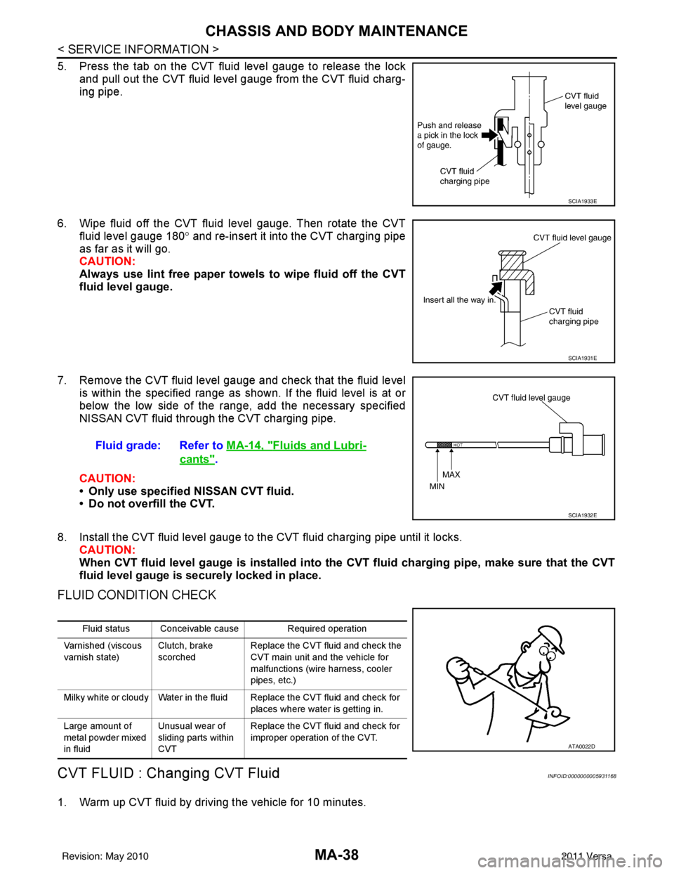
5. Press the tab on the CVT fluid level gauge to release the lockand pull out the CVT fluid level gauge from the CVT fluid charg-
ing pipe.
6. Wipe fluid off the CVT fluid level gauge. Then rotate the CVT fluid level gauge 180 ° and re-insert it into the CVT charging pipe
as far as it will go.
CAUTION:
Always use lint free paper towels to wipe fluid off the CVT
fluid level gauge.
7. Remove the CVT fluid level gauge and check that the fluid level is within the specified range as shown. If the fluid level is at or
below the low side of the range, add the necessary specified
NISSAN CVT fluid through the CVT charging pipe.
CAUTION:
• Only use specified NISSAN CVT fluid.
• Do not overfill the CVT.
8. Install the CVT fluid level gauge to the CVT fluid charging pipe until it locks. CAUTION:
When CVT fluid level gauge is in stalled into the CVT fluid charging pipe, make sure that the CVT
fluid level gauge is securely locked in place.
FLUID CONDITION CHECK
CVT FLUID : Chan ging CVT FluidINFOID:0000000005931168
1. Warm up CVT fluid by driving the vehicle for 10 minutes.
SCIA1933E
SCIA1931E
Fluid grade: Refer to MA-14, "Fluids and Lubri-
cants".
SCIA1932E
Fluid status Conceivable cause Required operation
Varnished (viscous
varnish state) Clutch, brake
scorchedReplace the CVT fluid and check the
CVT main unit and the vehicle for
malfunctions (wire harness, cooler
pipes, etc.)
Milky white or cloudy Water in the fluid Replace the CVT fluid and check for places where water is getting in.
Large amount of
metal powder mixed
in fluid Unusual wear of
sliding parts within
CVTReplace the CVT fluid and check for
improper operation of the CVT.
ATA0022D
Revision: May 2010
2011 Versa
Page 3210 of 3787
![NISSAN LATIO 2011 Service Repair Manual CHASSIS AND BODY MAINTENANCEMA-39
< SERVICE INFORMATION >
C
DE
F
G H
I
J
K
M A
B
MA
N
O P
• : Vehicle front
• Radiator (2)
• CVT fluid cooler hose [inlet side (3)]
• Transaxle assembly (4)
2. NISSAN LATIO 2011 Service Repair Manual CHASSIS AND BODY MAINTENANCEMA-39
< SERVICE INFORMATION >
C
DE
F
G H
I
J
K
M A
B
MA
N
O P
• : Vehicle front
• Radiator (2)
• CVT fluid cooler hose [inlet side (3)]
• Transaxle assembly (4)
2.](/manual-img/5/57357/w960_57357-3209.png)
CHASSIS AND BODY MAINTENANCEMA-39
< SERVICE INFORMATION >
C
DE
F
G H
I
J
K
M A
B
MA
N
O P
• : Vehicle front
• Radiator (2)
• CVT fluid cooler hose [inlet side (3)]
• Transaxle assembly (4)
2. Drain CVT fluid from CVT fluid cooler hose [outlet side (1)] and refill with new specified NISSAN CVT fluid in the CVT fluid
charging pipe with the engine running at idle speed.
CAUTION:
Only use the specifi ed NISSAN CVT fluid.
3. Refill until new CVT fluid comes out from CVT fluid cooler hose [outlet side (1)]. NOTE:
About 30 to 50% extra fluid will be required for this procedure.
4. Check fluid level and condition. Refer to MA-37, "
CVT FLUID : Checking CVT Fluid".
CAUTION:
Delete CVT fluid deterioration date with CONSULT-III after changing CVT fluid. Refer to CVT-48,
"CONSULT-III Function (TRANSMISSION)".
CLUTCH FLUID
CLUTCH FLUID : Air Bleeding ProcedureINFOID:0000000005931169
CAUTION:
Do not spill clutch fluid onto painted surfaces. If it spills, wipe up immediately and wash the affected
area with water.
NOTE:
• Do not use a vacuum assist or any other type of power bleeder on this system. Use of a vacuum assist or power bleeder will not purge all the air from the system.
• Carefully monitor fluid level in reservoir tank during bleeding operation.
1. Fill master cylinder reservoir tank with new clutch fluid.
2. Connect a transparent vinyl tube and container to the bleeding connector (1) on the CSC.
3. Depress and release the clutch pedal slowly and fully 15 times at an interval of two to three seconds and release the clutch
pedal.
4. Push in the lock pin (1) of the bleeding connector (2), and maintain the position. • RS5F91R transaxle models
CAUTION:
Hold the lock pin in to preven t the bleeding connector from
separating when fluid pressure is applied.
Fluid capacity and grade: Refer to
MA-14, "
Fluids
and Lubricants".SCIA6088E
PCIB1494E
PCIB1495E
Revision: May 2010 2011 Versa
Page 3211 of 3787
MA-40
< SERVICE INFORMATION >
CHASSIS AND BODY MAINTENANCE
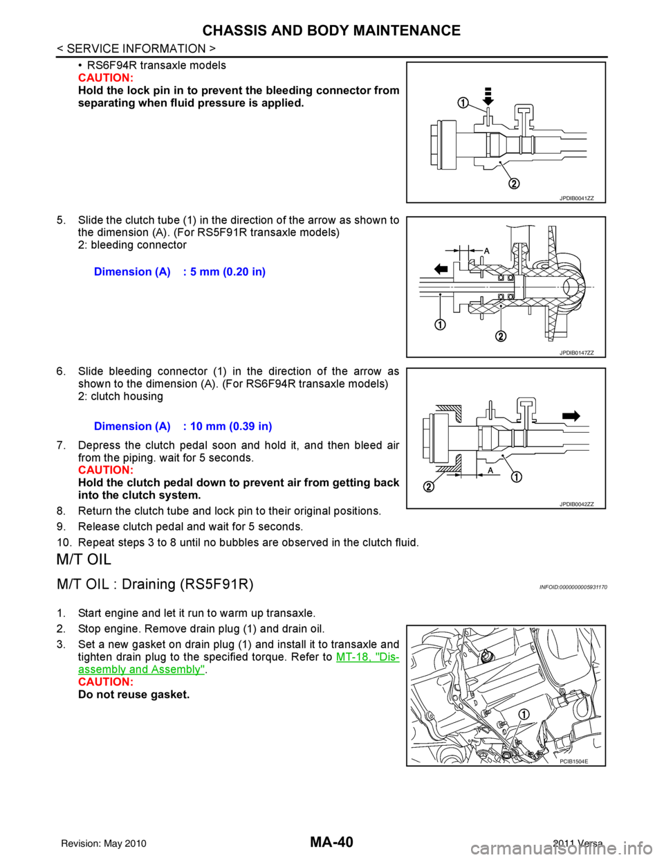
• RS6F94R transaxle models
CAUTION:
Hold the lock pin in to prevent the bleeding connector from
separating when fluid pressure is applied.
5. Slide the clutch tube (1) in the direction of the arrow as shown to the dimension (A). (For RS5F91R transaxle models)
2: bleeding connector
6. Slide bleeding connector (1) in the direction of the arrow as shown to the dimension (A). (For RS6F94R transaxle models)
2: clutch housing
7. Depress the clutch pedal soon and hold it, and then bleed air from the piping. wait for 5 seconds.
CAUTION:
Hold the clutch pedal down to prevent air from getting back
into the clutch system.
8. Return the clutch tube and lock pin to their original positions.
9. Release clutch pedal and wait for 5 seconds.
10. Repeat steps 3 to 8 until no bubbles are observed in the clutch fluid.
M/T OIL
M/T OIL : Draining (RS5F91R)INFOID:0000000005931170
1. Start engine and let it run to warm up transaxle.
2. Stop engine. Remove drain plug (1) and drain oil.
3. Set a new gasket on drain plug (1) and install it to transaxle and tighten drain plug to the specified torque. Refer to MT-18, "
Dis-
assembly and Assembly".
CAUTION:
Do not reuse gasket.
JPDIB0041ZZ
Dimension (A) : 5 mm (0.20 in)
JPDIB0147ZZ
Dimension (A) : 10 mm (0.39 in)
JPDIB0042ZZ
PCIB1504E
Revision: May 2010 2011 Versa