2011 NISSAN LATIO key fob battery
[x] Cancel search: key fob batteryPage 582 of 3787

BL-72
< SERVICE INFORMATION >
REMOTE KEYLESS ENTRY SYSTEM
Keyfob Battery and Function Check
INFOID:0000000005929313
1.CHECK KEYFOB FUNCTION
With CONSULT-III
Check keyfob function in “DATA MONITOR” mode with CONSULT-III. When pushing each button of keyfob,
the corresponding monitor item should be turned as follows.
Without CONSULT-III
Door lock does not function with keyfob.
(Power door lock system is “OK”.) 1. Check keyfob function. (Lock)
NOTE:
If the result of keyfob function check with CONSULT-III is OK, key-
fob is not malfunctioning.
BL-822. Replace keyfob. Refer to ID Code Entry Procedure.
BL-83
3. Check door switch (hatchback).BL-74
4. Check door switch (sedan).BL-76
5. Replace BCM.BCS-19
Door unlock does not function with keyfob
(Power door lock system is “OK”)1. Check keyfob function. (Unlock)
BL-82
2. Replace keyfob. Refer to ID Code Entry Procedure.
NOTE:
If the result of keyfob function check with CONSULT-III is OK, key-
fob is not malfunctioning.BL-83
3. Replace BCM.
BCS-19
Hazard reminder does not activate properly when
pressing lock or unlock button of keyfob.1. Check hazard reminder mode.*
*: Hazard reminder mode can be changed.
First check the hazard reminder setting.
BL-69
2. Check hazard function.
BL-79
3. Replace BCM.BCS-19
Panic alarm does not activate when panic alarm but-
ton is continuously pressed.1. Check panic alarm mode.*
*: Panic alarm mode can be changed.
First check the panic alarm setting.
BL-69
2. Check keyfob battery and function.
NOTE:
If the result of keyfob function check with CONSULT-III is OK, key-
fob is not malfunctioning.BL-72
3. Check horn function.
BL-79
4. Check key switch.BL-78
5. Replace keyfob. Refer to ID Code Entry Procedure.BL-83
6. Replace BCM.BCS-19
Auto door lock operation does not activate properly.
(All other remote keyless entry system functions are
OK.)1. Check auto door lock operation mode.*
*: Auto door lock operation mode can be changed.
First check the auto door lock operation setting.
BL-69
2. Replace BCM.
BCS-19
Interior lamp operation does not activate properly.1. Check interior lamp operation.
BL-802. Replace BCM.BCS-19
SymptomDiagnoses/service procedureReference
page
Condition Monitor item
Pushing LOCK KEYLESS LOCK: ON
Pushing UNLOCK KEYLESS UNLOCK: ON
Pushing PANIC KEYLESS PANIC: ON
Revision: May 2010 2011 Versa
Page 583 of 3787
REMOTE KEYLESS ENTRY SYSTEMBL-73
< SERVICE INFORMATION >
C
DE
F
G H
J
K L
M A
B
BL
N
O P
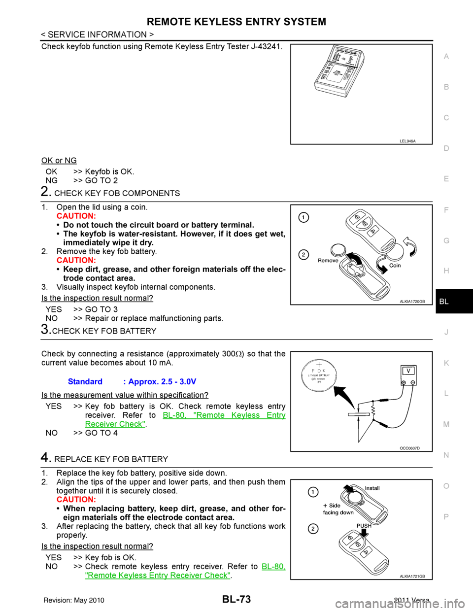
Check keyfob function using Remote Keyless Entry Tester J-43241.
OK or NG
OK >> Keyfob is OK.
NG >> GO TO 2
2. CHECK KEY FOB COMPONENTS
1. Open the lid using a coin. CAUTION:
• Do not touch the circuit board or battery terminal.
• The keyfob is water-resistant. However, if it does get wet,immediately wipe it dry.
2. Remove the key fob battery. CAUTION:
• Keep dirt, grease, and other fo reign materials off the elec-
trode contact area.
3. Visually inspect keyfob internal components.
Is the inspection result normal?
YES >> GO TO 3
NO >> Repair or replace malfunctioning parts.
3.CHECK KEY FOB BATTERY
Check by connecting a resistance (approximately 300 Ω) so that the
current value becomes about 10 mA.
Is the measurement val ue within specification?
YES >> Key fob battery is OK. Check remote keyless entry
receiver. Refer to BL-80, "
Remote Keyless Entry
Receiver Check".
NO >> GO TO 4
4. REPLACE KEY FOB BATTERY
1. Replace the key fob battery, positive side down.
2. Align the tips of the upper and lower parts, and then push them together until it is securely closed.
CAUTION:
• When replacing battery, keep dirt, grease, and other for-eign materials off the electrode contact area.
3. After replacing the battery, check that all key fob functions work properly.
Is the inspection result normal?
YES >> Key fob is OK.
NO >> Check remote keyless entry receiver. Refer to BL-80,
"Remote Keyless Entry Receiver Check".
LEL946A
ALKIA1720GB
Standard : Approx. 2.5 - 3.0V
OCC0607D
ALKIA1721GB
Revision: May 2010 2011 Versa
Page 595 of 3787
REMOTE KEYLESS ENTRY SYSTEMBL-85
< SERVICE INFORMATION >
C
DE
F
G H
J
K L
M A
B
BL
N
O P
• When registering an additional keyfob, the existing ID codes in memory may or may not be erased. If five ID
codes are stored in memory, when an additional code is registered, only the oldest code is erased. If less
than five ID codes are stored in memory, when an additional ID code is registered, the new ID code is added
and no ID codes are erased.
• If you need to activate more than two additional new keyfobs, repeat the procedure “Additional ID code
entry” for each new keyfob.
• Entry of maximum five ID codes is allowed. When mo re than five ID codes are entered, the oldest ID code
will be erased.
• Even if same ID code that is already in the memory is input, the same ID code can be entered. The code is
counted as an additional code.
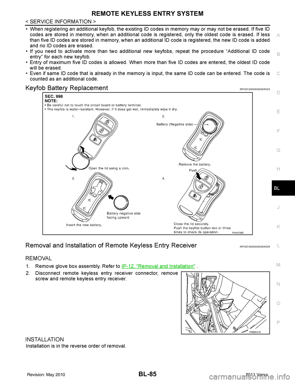
Keyfob Battery ReplacementINFOID:0000000005929325
Removal and Installation of Re mote Keyless Entry ReceiverINFOID:0000000005929326
REMOVAL
1. Remove glove box assembly. Refer to IP-12, "Removal and Installation" .
2. Disconnect remote keyless entry receiver connector, remove screw and remote keyless entry receiver.
INSTALLATION
Installation is in the reverse order of removal.
PIIA4706E
PIIB6541E
Revision: May 2010 2011 Versa
Page 622 of 3787
BL-112
< SERVICE INFORMATION >
INTELLIGENT KEY SYSTEM
15 WTire pressure warning
check connector
Input OFF
—5V
18 V Remote keyless entry
receiver (ground) Output OFF
—0V
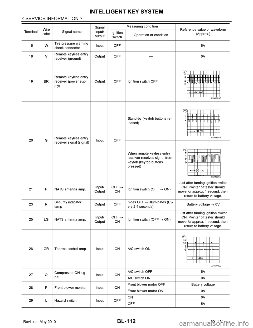
19 BR Remote keyless entry
receiver (power sup-
ply) Output OFF Ignition switch OFF
20 G Remote keyless entry
receiver signal (signal)
Input OFFStand-by (keyfob buttons re-
leased)
When remote keyless entry
receiver receives signal from
keyfob (keyfob buttons
pressed)
21 P NATS antenna amp. Input/
Output OFF
→
ON Ignition switch (OFF
→ ON)Just after turning ignition switch
ON: Pointer of tester should
move for approx. 1 second, then
return to battery voltage.
23 R Security indicator
lamp Output OFF
Goes OFF
→ illuminates (Ev-
ery 2.4 seconds) Battery voltage
→ 0V
25 LG NATS antenna amp. Input/
Output OFF
→
ON Ignition switch (OFF
→ ON)Just after turning ignition switch
ON: Pointer of tester should
move for approx. 1 second, then return to battery voltage.
26 GR Thermo control amp. Input ON A/C switch ON
27 O Compressor ON sig-
nal Input ONA/C switch OFF
5V
A/C switch ON 0V
28 P Front blower monitor Input ON Front blower motor OFF
Battery voltage
Front blower motor ON 0V
29 L Hazard switch Input OFFON
0V
OFF 5V
Te r m i n a l
Wire
color Signal name Signal
input/
output Measuring condition
Reference value or waveform
(Approx.)
Ignition
switch Operation or condition
LIIA1893E
LIIA1894E
LIIA1895E
ZJIA0719J
Revision: May 2010
2011 Versa
Page 629 of 3787

INTELLIGENT KEY SYSTEMBL-119
< SERVICE INFORMATION >
C
DE
F
G H
J
K L
M A
B
BL
N
O P
Trouble Diagnosis Symptom ChartINFOID:0000000005929340
KEY WARNING LAMP (GREEN) ILLUMINATES
NOTE:
Monitor item Description
CONFIRM KEY FOB ID It can be checked whether Intelligent Key ID code is registered or not in this mode.
TAKE OUT FROM WINDOW
WARN Take away warning chime (from window) mode can be changed to operate (ON) or not operate
(OFF) with this mode. The operation mode will be changed when “CHANGE SETT” on CONSULT-
III screen is touched.
LOW BAT OF KEY FOB WARN Intelligent Key low battery warning mode can be changed to operate (ON) or not operate (OFF)
with this mode. The operation mode will be changed when “CHANGE
SETT” on CONSULT-III
screen is touched.
ANSWER BACK FUNCTION Buzzer reminder function mode by Intelligent button can be changed to operate (ON) or not oper-
ate (OFF) with this mode. The operation mode will be changed when “CHANGE SETT” on CON-
SULT-III screen is touched.
SELECTIVE UNLOCK FUNC-
TION Selective unlock function mode can be changed to operate (ON) or not operate (OFF) with this
mode. The operation mode will be changed when “CHANGE SETT” on CONSULT-III screen is
touched.
ANTI KEY LOCK IN FUNCTION Key reminder function mode can be changed to operate (ON) or not operate (OFF) with this mode.
The operation mode will be changed when “CHANGE SETT” on CONSULT-III screen is touched.
HORN WITH KEYLESS LOCK Horn reminder function mode by Intelligent Key remote control button can be changed to operate
(ON) or not operate (OFF) with this mode. The operation mode will be changed when “CHANGE
SETT” on CONSULT-III screen is touched.
HAZARD ANSWER BACK Hazard reminder function mode can be selected from the following with this mode. The operation
mode will be changed when “CHANGE SE
TT” on CONSULT-III screen is touched.
• LOCK ONLY: Door lock operation only
• UNLOCK ONLY: Door unlock operation only
• LOCK/UNLOCK: Lock/Unlock operation
• OFF: Non-operation
ANSWER BACK WITH I-KEY
LOCK Buzzer reminder function (lock operation) mode by door request switch (driver side, passenger
side and back door side) can be selected from the following with this mode. The operation mode
will be changed when “
CHANGE SETT” on CONSULT- III screen is touched.
• BUZZER: Sound buzzer
• OFF: Non-operation
ANSWER BACK WITH I-KEY UN-
LOCK Buzzer reminder function (unlock operation) mode by door request switch can be changed to op-
erate (ON) or not operate (OFF) with this mode.
AUTO RELOCK TIMER Auto door lock timer mode can select the following with this mode.
• 1 minute
• OFF: Non-operation
PANIC ALARM DELAY Panic alarm button's pressing time on Intelligent Key remote control button can be selected from
the following with this mode. The operation mode will be changed when “CHANGE SETT” on
CONSULT-III screen is touched.
• 0.5 second
• 1.5 second
• OFF: Non-operation
P/W DOWN DELAY Unlock button's pressing time on Intelligent Key remote control button can be selected from the
following with this mode. The operation mode will be changed when “CHANGE SETT” on CON-
SULT-III screen is touched.
• 3 seconds
• 5 seconds
• OFF: Non-operation
ENGINE START BY I-KEY Engine start function mode can be changed to operate (ON) or not operate (OFF) with this mode.
The operation mode will be changed when “CHANGE SETT” on CONSULT-III screen is touched.
LOCK/UNLOCK BY I-KEY Door lock/unlock function by door request switch (driver side, passenger side and back door side)
mode can be changed to operate (ON) or not operate (OFF) with this mode. The operation mode
will be changed when “
CHANGE SETT” on CONSULT- III screen is touched.
Revision: May 2010 2011 Versa
Page 636 of 3787
BL-126
< SERVICE INFORMATION >
INTELLIGENT KEY SYSTEM
CAN Communication System Inspection
INFOID:0000000005929341
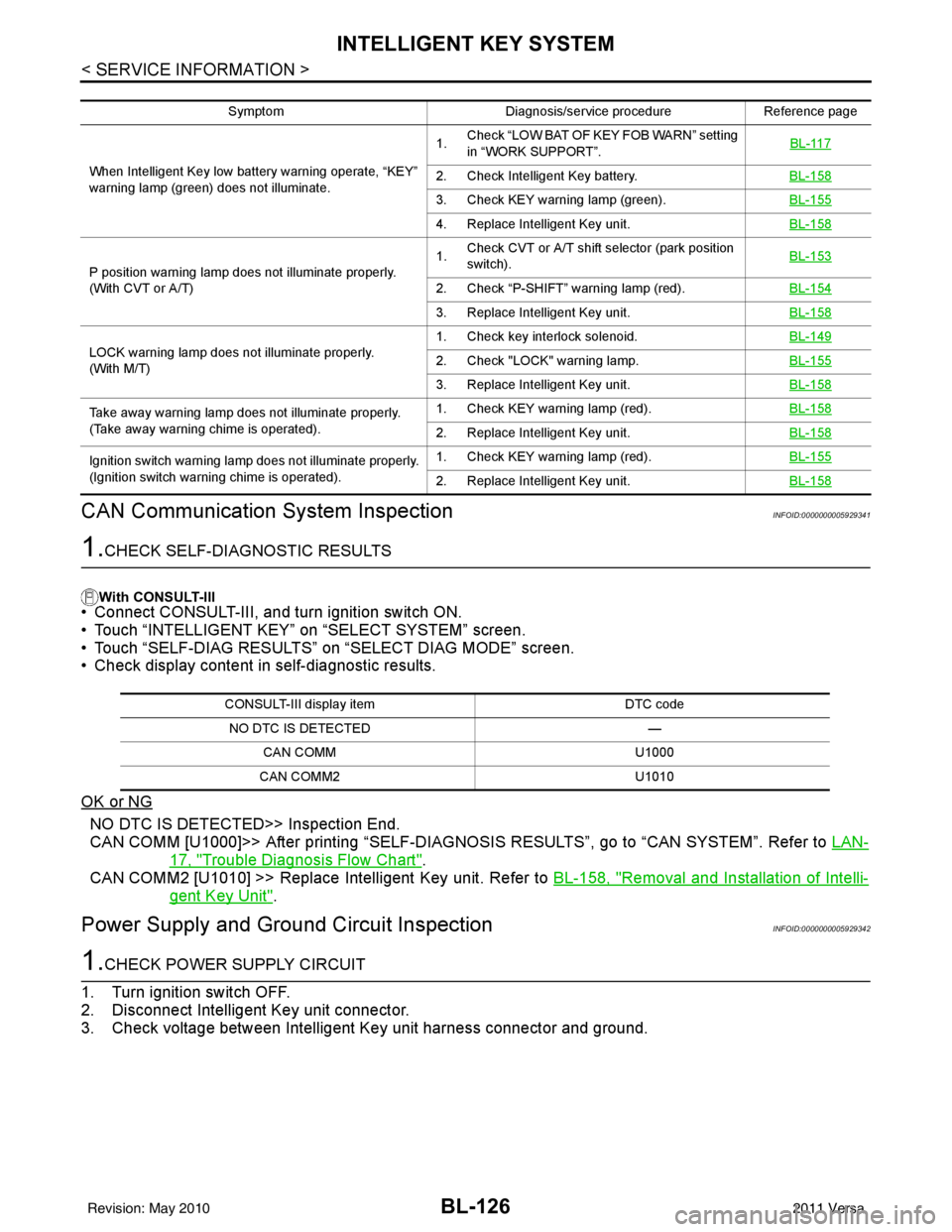
1.CHECK SELF-DIAGNOSTIC RESULTS
With CONSULT-III
• Connect CONSULT-III, and turn ignition switch ON.
• Touch “INTELLIGENT KEY” on “SELECT SYSTEM” screen.
• Touch “SELF-DIAG RESULTS” on “SELECT DIAG MODE” screen.
• Check display content in self-diagnostic results.
OK or NG
NO DTC IS DETECT ED>> Inspection End.
CAN COMM [U1000]>> After printing “SELF-DIAGNOSI S RESULTS”, go to “CAN SYSTEM”. Refer to LAN-
17, "Trouble Diagnosis Flow Chart".
CAN COMM2 [U1010] >> Replace Intelligent Key unit. Refer to BL-158, "
Removal and Installation of Intelli-
gent Key Unit".
Power Supply and Ground Circuit InspectionINFOID:0000000005929342
1.CHECK POWER SUPPLY CIRCUIT
1. Turn ignition switch OFF.
2. Disconnect Intelligent Key unit connector.
3. Check voltage between Intelligent Key unit harness connector and ground.
Symptom Diagnosis/service procedureReference page
When Intelligent Key low batt ery warning operate, “KEY”
warning lamp (green) does not illuminate. 1.
Check “LOW BAT OF KEY FOB WARN” setting
in “WORK SUPPORT”. BL-117
2. Check Intelligent Key battery.
BL-158
3. Check KEY warning lamp (green).BL-155
4. Replace Intelligent Key unit.BL-158
P position warning lamp does not illuminate properly.
(With CVT or A/T)1.
Check CVT or A/T shift selector (park position
switch). BL-153
2. Check “P-SHIFT” warning lamp (red).
BL-154
3. Replace Intelligent Key unit.BL-158
LOCK warning lamp does not illuminate properly.
(With M/T)1. Check key interlock solenoid.
BL-1492. Check "LOCK" warning lamp.BL-155
3. Replace Intelligent Key unit.BL-158
Take away warning lamp does not illuminate properly.
(Take away warning chime is operated).1. Check KEY warning lamp (red).
BL-158
2. Replace Intelligent Key unit.BL-158
Ignition switch warning lamp does not illuminate properly.
(Ignition switch warning chime is operated).1. Check KEY warning lamp (red).
BL-155
2. Replace Intelligent Key unit.BL-158
CONSULT-III display item DTC code
NO DTC IS DETECTED —
CAN COMM U1000
CAN COMM2 U1010
Revision: May 2010 2011 Versa
Page 668 of 3787
BL-158
< SERVICE INFORMATION >
INTELLIGENT KEY SYSTEM
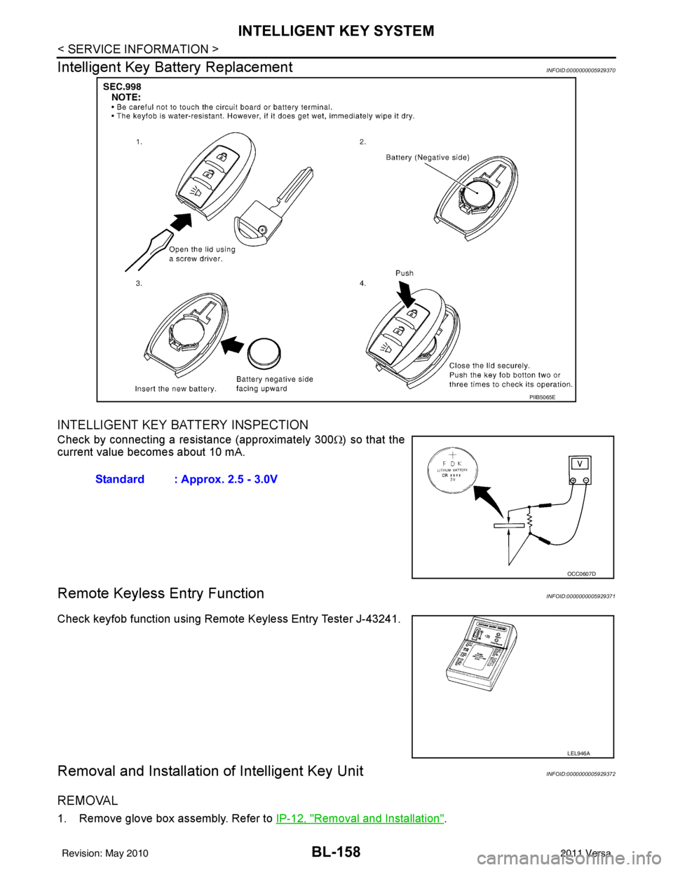
Intelligent Key Battery Replacement
INFOID:0000000005929370
INTELLIGENT KEY BATTERY INSPECTION
Check by connecting a resistance (approximately 300 Ω) so that the
current value becomes about 10 mA.
Remote Keyless Entry FunctionINFOID:0000000005929371
Check keyfob function using Remote Keyless Entry Tester J-43241.
Removal and Installation of Intelligent Key UnitINFOID:0000000005929372
REMOVAL
1. Remove glove box assembly. Refer to IP-12, "Removal and Installation".
PIIB5065E
Standard : Approx. 2.5 - 3.0V
OCC0607D
LEL946A
Revision: May 2010 2011 Versa
Page 687 of 3787
BACK DOOR LOCKBL-177
< SERVICE INFORMATION >
C
DE
F
G H
J
K L
M A
B
BL
N
O P
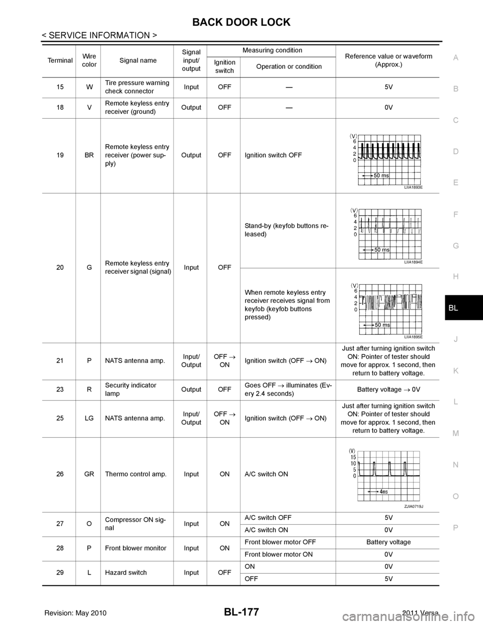
15 W Tire pressure warning
check connector
Input OFF
—5V
18 V Remote keyless entry
receiver (ground) Output OFF
—0V
19 BR Remote keyless entry
receiver (power sup-
ply) Output OFF Ignition switch OFF
20 G Remote keyless entry
receiver signal (signal)
Input OFFStand-by (keyfob buttons re-
leased)
When remote keyless entry
receiver receives signal from
keyfob (keyfob buttons
pressed)
21 P NATS antenna amp. Input/
Output OFF
→
ON Ignition switch (OFF → ON) Just after turning ignition switch
ON: Pointer of tester should
move for approx. 1 second, then
return to battery voltage.
23 R Security indicator
lamp Output OFF
Goes OFF
→ illuminates (Ev-
ery 2.4 seconds) Battery voltage
→ 0V
25 LG NATS antenna amp. Input/
Output OFF
→
ON Ignition switch (OFF → ON) Just after turning ignition switch
ON: Pointer of tester should
move for approx. 1 second, then return to battery voltage.
26 GR Thermo control amp. Input ON A/C switch ON
27 O Compressor ON sig-
nal Input ONA/C switch OFF
5V
A/C switch ON 0V
28 P Front blower monitor Input ON Front blower motor OFF
Battery voltage
Front blower motor ON 0V
29 L Hazard switch Input OFFON
0V
OFF 5V
Te r m i n a l
Wire
color Signal name Signal
input/
output Measuring condition
Reference value or waveform
(Approx.)
Ignition
switch Operation or condition
LIIA1893E
LIIA1894E
LIIA1895E
ZJIA0719J
Revision: May 2010
2011 Versa