2011 NISSAN LATIO ignition
[x] Cancel search: ignitionPage 2709 of 3787
PRECAUTIONSGI-5
< SERVICE INFORMATION >
C
DE
F
G H
I
J
K L
M B
GI
N
O P
(i.e. Flexible Fuel Vehicle - FFV models). Using a fu el other than that specified could adversely affect
the emission control devices and systems, and could also affect the warranty coverage validity.
Precaution for Multiport Fuel Injection System or Engine Control SystemINFOID:0000000005929714
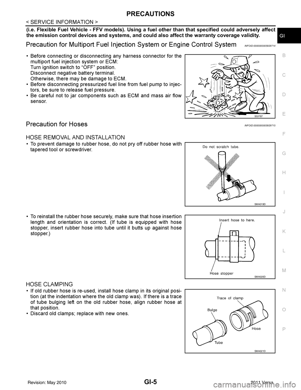
• Before connecting or disconnecting any harness connector for the
multiport fuel injection system or ECM:
Turn ignition switch to “OFF” position.
Disconnect negative battery terminal.
Otherwise, there may be damage to ECM.
• Before disconnecting pressurized fuel line from fuel pump to injec- tors, be sure to release fuel pressure.
• Be careful not to jar components such as ECM and mass air flow sensor.
Precaution for HosesINFOID:0000000005929715
HOSE REMOVAL AND INSTALLATION
• To prevent damage to rubber hose, do not pry off rubber hose withtapered tool or screwdriver.
• To reinstall the rubber hose securely, make sure that hose insertion length and orientation is correct. (If tube is equipped with hose
stopper, insert rubber hose into tube until it butts up against hose
stopper.)
HOSE CLAMPING
• If old rubber hose is re-used, install hose clamp in its original posi-tion (at the indentation where the old clamp was). If there is a trace
of tube bulging left on the old rubber hose, align rubber hose at
that position.
• Discard old clamps; replace with new ones.
SGI787
SMA019D
SMA020D
SMA021D
Revision: May 2010 2011 Versa
Page 2714 of 3787
GI-10
< SERVICE INFORMATION >
HOW TO USE THIS MANUAL
3.Refer to Component Parts and Harness Connector Location for the Systems described in each
section for identifi cation/location of componen ts and harness connectors.
4. Refer to the Circuit Diagram for quick pinpoint check.
If you need to check circuit continuity between harness connectors in more detail, such as when a
sub-harness is used, refer to Wiring Diagram in each individual section and Harness Layout in PG
section for identificatio n of harness connectors.
5. When checking circuit continuity, ignition switch should be OFF.
6. Before checking voltage at co nnectors, check battery voltage.
7. After accomplishing the Diagnostic Procedures an d Electrical Components Inspection, make sure
that all harness connectors ar e reconnected as they were.
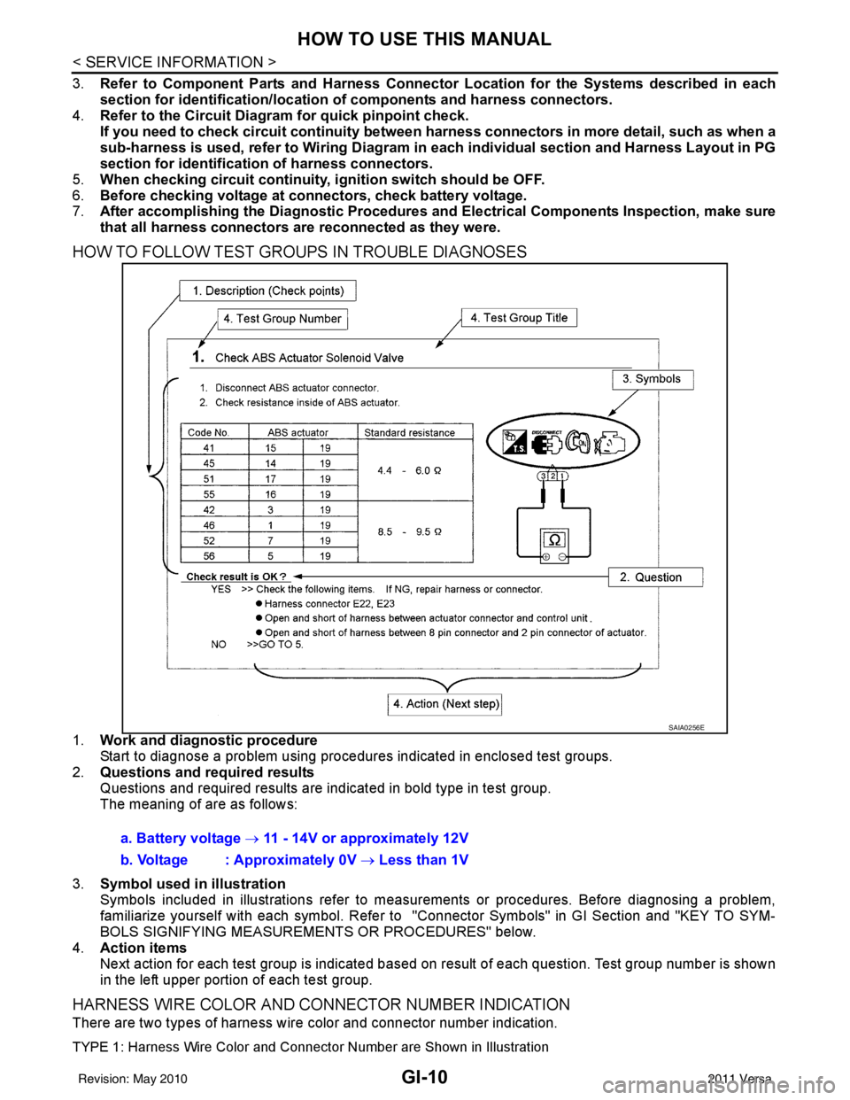
HOW TO FOLLOW TEST GROUPS IN TROUBLE DIAGNOSES
1.Work and diagnostic procedure
Start to diagnose a problem using procedures indicated in enclosed test groups.
2. Questions and required results
Questions and required results are indicated in bold type in test group.
The meaning of are as follows:
3. Symbol used in illustration
Symbols included in illustrations refer to measurements or procedures. Before diagnosing a problem,
familiarize yourself with each symbol. Refer to "Connector Symbols" in GI Section and "KEY TO SYM-
BOLS SIGNIFYING MEASUREME NTS OR PROCEDURES" below.
4. Action items
Next action for each test group is indicated based on result of each question. Test group number is shown
in the left upper portion of each test group.
HARNESS WIRE COLOR AND CONNECTOR NUMBER INDICATION
There are two types of harness wire color and connector number indication.
TYPE 1: Harness Wire Color and Connector Number are Shown in Illustration
SAIA0256E
a. Battery voltage → 11 - 14V or approximately 12V
b. Voltage : Approximately 0V → Less than 1V
Revision: May 2010 2011 Versa
Page 2722 of 3787
GI-18
< SERVICE INFORMATION >
HOW TO USE THIS MANUAL
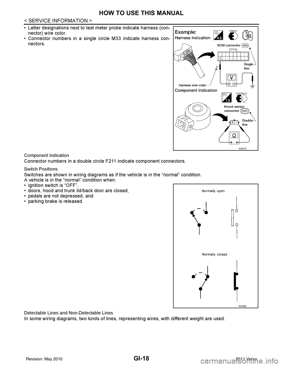
• Letter designations next to test meter probe indicate harness (con-nector) wire color.
• Connector numbers in a single circle M33 indicate harness con-
nectors.
Component Indication
Connector numbers in a double circle F211 indicate component connectors.
Switch Positions
Switches are shown in wiring diagrams as if the vehicle is in the “normal” condition.
A vehicle is in the “normal” condition when:
• ignition switch is “OFF”,
• doors, hood and trunk lid/back door are closed,
• pedals are not depressed, and
• parking brake is released.
Detectable Lines and Non-Detectable Lines
In some wiring diagrams, two kinds of lines, r epresenting wires, with different weight are used.
AGI070
SGI860
Revision: May 2010 2011 Versa
Page 2733 of 3787
SERVICE INFORMATION FOR ELECTRICAL INCIDENTGI-29
< SERVICE INFORMATION >
C
DE
F
G H
I
J
K L
M B
GI
N
O P
• Close the relay and probe at the solenoid. voltage; open is further down the circuit than the solenoid.
no voltage; open is between relay and solenoid (point C).
Any powered circuit can be diagnosed using the approach in the previous example.
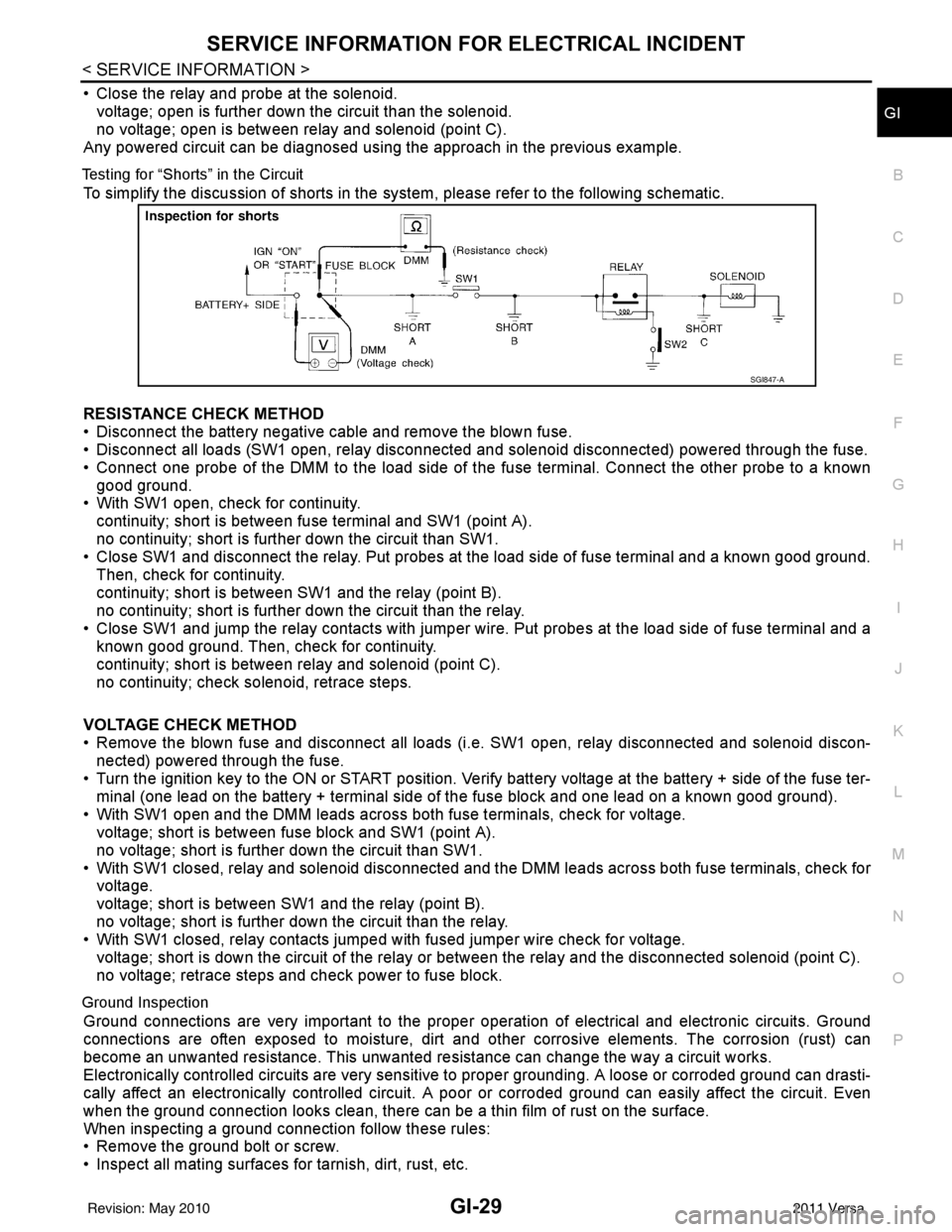
Testing for “Shorts” in the Circuit
To simplify the discussion of shorts in the system, please refer to the following schematic.
RESISTANCE CHECK METHOD
• Disconnect the battery negative cable and remove the blown fuse.
• Disconnect all loads (SW1 open, relay disconnected and solenoid disconnected) powered through the fuse.
• Connect one probe of the DMM to the load side of the fuse terminal. Connect the other probe to a known
good ground.
• With SW1 open, check for continuity.
continuity; short is between fuse terminal and SW1 (point A).
no continuity; short is further down the circuit than SW1.
• Close SW1 and disconnect the relay. Put probes at the load side of fuse terminal and a known good ground.
Then, check for continuity.
continuity; short is between SW1 and the relay (point B).
no continuity; short is further down the circuit than the relay.
• Close SW1 and jump the relay contacts with jumper wir e. Put probes at the load side of fuse terminal and a
known good ground. Then, check for continuity.
continuity; short is between relay and solenoid (point C).
no continuity; check solenoid, retrace steps.
VOLTAGE CHECK METHOD
• Remove the blown fuse and disconnect all loads (i .e. SW1 open, relay disconnected and solenoid discon-
nected) powered through the fuse.
• Turn the ignition key to the ON or START position. Veri fy battery voltage at the battery + side of the fuse ter-
minal (one lead on the battery + terminal side of the fuse block and one lead on a known good ground).
• With SW1 open and the DMM leads across both fuse terminals, check for voltage.
voltage; short is between fuse block and SW1 (point A).
no voltage; short is further down the circuit than SW1.
• With SW1 closed, relay and solenoid disconnected and the DMM leads across both fuse terminals, check for voltage.
voltage; short is between SW1 and the relay (point B).
no voltage; short is further down the circuit than the relay.
• With SW1 closed, relay contacts jumped with fused jumper wire check for voltage.
voltage; short is down the circuit of the relay or between the relay and the disconnected solenoid (point C).
no voltage; retrace steps and check power to fuse block.
Ground Inspection
Ground connections are very important to the proper oper ation of electrical and electronic circuits. Ground
connections are often exposed to moisture, dirt and other corrosive elements. The corrosion (rust) can
become an unwanted resistance. This unwanted resistance can change the way a circuit works.
Electronically controlled circuits are very sensitive to proper grounding. A loose or corroded ground can drasti-
cally affect an electronically controlled circuit. A poor or corroded ground can easily affect the circuit. Even
when the ground connection looks clean, there can be a thin film of rust on the surface.
When inspecting a ground connection follow these rules:
• Remove the ground bolt or screw.
• Inspect all mating surfaces for tarnish, dirt, rust, etc.
SGI847-A
Revision: May 2010 2011 Versa
Page 2751 of 3787

TERMINOLOGYGI-47
< SERVICE INFORMATION >
C
DE
F
G H
I
J
K L
M B
GI
N
O PTERMINOLOGY
SAE J1930 Terminology ListINFOID:0000000005929743
All emission related terms used in this publication in accordance with SAE J1930 are listed. Accordingly, new
terms, new acronyms/abbreviations and old terms are listed in the following chart.
NEW TERM NEW ACRONYM /
ABBREVIATION OLD TERM
Air cleaner ACL Air cleaner
Barometric pressure BARO ***
Barometric pressure sensor-BCDD BAROS-BCDD BCDD
Camshaft position CMP***
Camshaft position sensor CMPSCrank angle sensor
Canister ***Canister
Carburetor CARB Carburetor
Charge air cooler CACIntercooler
Closed loop CLClosed loop
Closed throttle position switch CTP switchIdle switch
Clutch pedal position switch CPP switchClutch switch
Continuous fuel injection system CFI system ***
Continuous trap oxidizer system CTOX system***
Crankshaft position CKP ***
Crankshaft position sensor CKPS ***
Data link connector DLC***
Data link connector fo r CONSULT-III DLC for CONSULT-III Diagnostic connector for CONSULT-III
Diagnostic test mode DTMDiagnostic mode
Diagnostic test mode selector DTM selectorDiagnostic mode selector
Diagnostic test mode I DTM IMode I
Diagnostic test mode II DTM IIMode II
Diagnostic trouble code DTCMalfunction code
Direct fuel injection system DFI system ***
Distributor ignition system DI system Ignition timing control
Early fuel evaporation-mixture heater EFE-mixture heater Mixture heater
Early fuel evaporation system EFE systemMixture heater control
Electrically erasable programmable read
only memory EEPROM
***
Electronic ignition system EI systemIgnition timing control
Engine control EC ***
Engine control module ECMECCS control unit
Engine coolant temperature ECTEngine temperature
Engine coolant temperature sensor ECTS Engine temperature sensor
Engine modification EM ***
Engine speed RPMEngine speed
Erasable programmable read only memory EPROM ***
Evaporative emission canister EVAP canisterCanister
Evaporative emission system EVAP systemCanister control solenoid valve
Exhaust gas recirculation valve EGR valve EGR valve
Revision: May 2010 2011 Versa
Page 2752 of 3787

GI-48
< SERVICE INFORMATION >
TERMINOLOGY
Exhaust gas recirculation control-BPT
valveEGRC-BPT valve
BPT valve
Exhaust gas recirculation control-solenoid
valve EGRC-solenoid valve
EGR control solenoid valve
Exhaust gas recirculation temperature sen-
sor EGRT sensorExhaust gas temperature sensor
EGR temperature sensor
Flash electrically erasable programmable
read only memory FEEPROM
***
Flash erasable programmable read only
memory FEPROM
***
Flexible fuel sensor FFS ***
Flexible fuel system FF system ***
Fuel pressure regulato r*** Pressure regulator
Fuel pressure regulator control solenoid
valve ***
PRVR control solenoid valve
Fuel trim FT ***
Heated Oxygen sensor HO2S Exhaust gas sensor
Idle air control system IAC system Idle speed control
Idle air control valve- air regulator IACV-air regulator Air regulator
Idle air control valve- auxiliary air control
valve IACV-AAC valve
Auxiliary air control (AAC) valve
Idle air control valve-FICD solenoid valve IACV-FICD solenoid valve FICD solenoid valve
Idle air control valve-idle up control sole-
noid valve IACV-idle up control solenoid valve Idle up control solenoid valve
Idle speed control-FI pot ISC-FI potFI pot
Idle speed control system ISC system ***
Ignition control IC***
Ignition control module ICM***
Indirect fuel injection system IFI system ***
Intake air IA Air
Intake air temperature sensor IAT sensor Air temperature sensor
Knock *** Detonation
Knock sensor KS Detonation sensor
Malfunction indicator lamp MIL Check engine light
Manifold absolute pressure MAP ***
Manifold absolute pressure sensor MAPS ***
Manifold differential pressure MDP ***
Manifold differential pressure sensor MDPS ***
Manifold surface temperature MST***
Manifold surface temperature sensor MSTS ***
Manifold vacuum zone MVZ ***
Manifold vacuum zone sensor MVZS ***
Mass air flow sensor MAFS Air flow meter
Mixture control solenoid valve MC solenoid valveAir-fuel ratio control solenoid valve
Multiport fuel injection System MFI system Fuel injection control
NEW TERM
NEW ACRONYM /
ABBREVIATION OLD TERM
Revision: May 2010
2011 Versa
Page 2757 of 3787
PRECAUTIONSGW-3
< SERVICE INFORMATION >
C
DE
F
G H
J
K L
M A
B
GW
N
O P
SERVICE INFORMATION
PRECAUTIONS
Precaution for Supplemental Restraint System (SRS) "AIR BAG" and "SEAT BELT
PRE-TENSIONER"
INFOID:0000000005929457
The Supplemental Restraint System such as “AIR BAG” and “SEAT BELT PRE-TENSIONER”, used along
with a front seat belt, helps to reduce the risk or severi ty of injury to the driver and front passenger for certain
types of collision. This system includes seat belt switch inputs and dual stage front air bag modules. The SRS
system uses the seat belt switches to determine the front air bag deployment, and may only deploy one front
air bag, depending on the severity of a collision and w hether the front occupants are belted or unbelted.
Information necessary to service the system safely is included in the SRS and SB section of this Service Man-
ual.
WARNING:
• To avoid rendering the SRS inoper ative, which could increase the risk of personal injury or death in
the event of a collision which would result in air bag inflation, all maintenance must be performed by
an authorized NISSAN/INFINITI dealer.
• Improper maintenance, including in correct removal and installation of the SRS can lead to personal
injury caused by unintentional act ivation of the system. For removal of Spiral Cable and Air Bag
Module, see the SRS section.
• Do not use electrical test equipm ent on any circuit related to the SRS unless instructed to in this
Service Manual. SRS wiring harnesses can be identi fied by yellow and/or orange harnesses or har-
ness connectors.
PRECAUTIONS WHEN USING POWER TOOLS (AIR OR ELECTRIC) AND HAMMERS
WARNING:
• When working near the Airbag Diagnosis Sensor Un it or other Airbag System sensors with the Igni-
tion ON or engine running, DO NOT use air or el ectric power tools or strike near the sensor(s) with a
hammer. Heavy vibration could activate the sensor( s) and deploy the air bag(s), possibly causing
serious injury.
• When using air or electric power tools or hammers, always switch the Ignition OFF, disconnect the battery, and wait at least 3 minutes before performing any service.
Precaution Necessary for Steering Wheel Rotation After Battery Disconnect
INFOID:0000000005929458
NOTE:
• This Procedure is applied only to models with Intelligent Key system and NATS (NISSAN ANTI-THEFT SYS-
TEM).
• Remove and install all control units after disconnecti ng both battery cables with the ignition knob in the
″ LOCK ″ position.
• Always use CONSULT-III to perform self-diagnosis as a part of each function inspection after finishing work.
If DTC is detected, perform trouble diagnosis according to self-diagnostic results.
For models equipped with the Intelligent Key system and NATS , an electrically controlled steering lock mech-
anism is adopted on the key cylinder.
For this reason, if the battery is disconnected or if the battery is discharged, the steering wheel will lock and
steering wheel rotation will become impossible.
If steering wheel rotation is required when battery power is interrupted, follow the procedure below before
starting the repair operation.
OPERATION PROCEDURE
1. Connect both battery cables. NOTE:
Supply power using jumper cables if battery is discharged.
2. Use the Intelligent Key or mechanical key to turn the ignition switch to the ″ACC ″ position. At this time, the
steering lock will be released.
3. Disconnect both battery cables. The steering lock will remain released and the steering wheel can be
rotated.
4. Perform the necessary repair operation.
Revision: May 2010 2011 Versa
Page 2758 of 3787
GW-4
< SERVICE INFORMATION >
PRECAUTIONS
5. When the repair work is completed, return the ignition switch to the ″LOCK ″ position before connecting
the battery cables. (At this time, the steering lock mechanism will engage.)
6. Perform a self-diagnosis check of a ll control units using CONSULT-III.
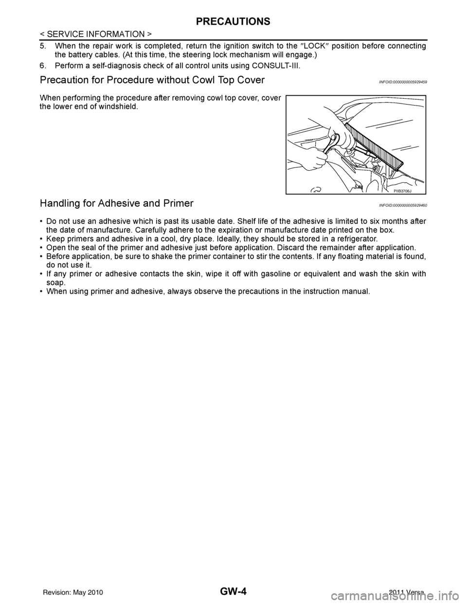
Precaution for Procedure without Cowl Top CoverINFOID:0000000005929459
When performing the procedure after removing cowl top cover, cover
the lower end of windshield.
Handling for Adhesive and PrimerINFOID:0000000005929460
• Do not use an adhesive which is past its usable date. Shel f life of the adhesive is limited to six months after
the date of manufacture. Carefully adhere to the expiration or manufacture date printed on the box.
• Keep primers and adhesive in a cool, dry place. Ideally, they should be stored in a refrigerator.
• Open the seal of the primer and adhesive just before application. Discard the remainder after application.
• Before application, be sure to shake the primer container to stir the contents. If any floating material is found, do not use it.
• If any primer or adhesive contacts the skin, wipe it off with gasoline or equivalent and wash the skin with
soap.
• When using primer and adhesive, always observe the precautions in the instruction manual.
PIIB3706J
Revision: May 2010 2011 Versa