2011 NISSAN LATIO sensor
[x] Cancel search: sensorPage 3681 of 3787
OCCUPANT CLASSIFICATION SYSTEM CONTROL UNITSRS-47
< ON-VEHICLE REPAIR >
C
DE
F
G
I
J
K L
M A
B
SRS
N
O P
OCCUPANT CLASSIFICATION SYSTEM CONTROL UNIT
Removal and InstallationINFOID:0000000005931220
The occupant classification system control unit, occupant classification system sensor, and bladder are an
integral part of the front passenger seat cushion and are replaced as an assembly. Refer to SE-11
to remove
the seat, and SE-13, "
Disassembly and Assembly" to replace the seat cushion.
Revision: May 2010 2011 Versa
Page 3682 of 3787
SRS-48
< ON-VEHICLE REPAIR >
COLLISION DIAGNOSIS
COLLISION DIAGNOSIS
For Frontal CollisionINFOID:0000000005931221
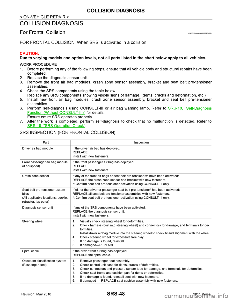
FOR FRONTAL COLLISION: When SRS is activated in a collision
CAUTION:
Due to varying models and option levels, not all parts listed in the chart below apply to all vehicles.
WORK PROCEDURE
1. Before performing any of the following steps, ensure that all vehicle body and structural repairs have been
completed.
2. Replace the diagnosis sensor unit.
3. Remove the front air bag modules, crash zone sens or assembly, bracket and seat belt pre-tensioner
assemblies.
4. Check the SRS components using the table below: Replace any SRS components showing visible signs of damage. (dents, cracks and deformation, etc.)
5. Install new front air bag modules, crash zone sens or assembly, bracket and seat belt pre-tensioner
assemblies.
6. Perform self-diagnosis using CONSULT-III or air bag warning lamp. Refer to SRS-18, "
Self-Diagnosis
Function (Without CONSULT-III)" for details.
Ensure entire SRS operates properly.
7. After the work is completed, perform self-diagnosis to check that no malfunction is detected. Refer to SRS-19, "
SRS Operation Check".
SRS INSPECTION (FOR FRONTAL COLLISION)
Part Inspection
Driver air bag module If the driver air bag has deployed:
REPLACE
Install with new fasteners.
Front passenger air bag module
(if equipped) If the front passenger air bag has deployed:
REPLACE
Install with new fasteners.
Crash zone sensor If any of the front air bags or seat belt pre-tensioners* have been activated:
REPLACE the crash zone sensor and bracket with new fasteners.
*: Confirm seat belt pre-tensioner activation using CONSULT-III only.
Seat belt pre-tensioner assem-
blies
(All applicable locations: buckle,
retractor, lap outer) If either the driver or passenger seat belt pre-tensioner* has been activated:
REPLACE all seat belt pre-tensioner assemblies with new fasteners.
*: Confirm seat belt pre-tensioner activation using CONSULT-III only.
Diagnosis sensor unit If any of the SRS components have been activated:
REPLACE the diagnosis sensor unit.
Install with new fasteners.
Steering wheel 1. Visually check steering wheel for deformities.
2. Check harness (built into steering wheel) and connectors for damage, and terminals for de- formities.
3. Install driver air bag module into the steering wheel to check fit and alignment with the wheel.
4. Check steering wheel for excessive free play.
5. If no damage is found, reinstall.
6. If damaged—REPLACE.
Spiral cable If the driver front air bag has deployed:
REPLACE the spiral cable.
Occupant classification system
(Passenger seat) 1. Remove passenger seat assembly.
2. Check control unit case for dents, cracks of deformities.
3. Check connectors and pressure sensor tube for damage, and terminals for deformities.
4. Check seat frame and cushion pan for dents or deformities.
5. If no damage is found, reinstall seat with new fasteners.
6. If damaged — REPLACE seat cushion assembly with new fasteners.
Revision: May 2010
2011 Versa
Page 3683 of 3787
COLLISION DIAGNOSISSRS-49
< ON-VEHICLE REPAIR >
C
DE
F
G
I
J
K L
M A
B
SRS
N
O P
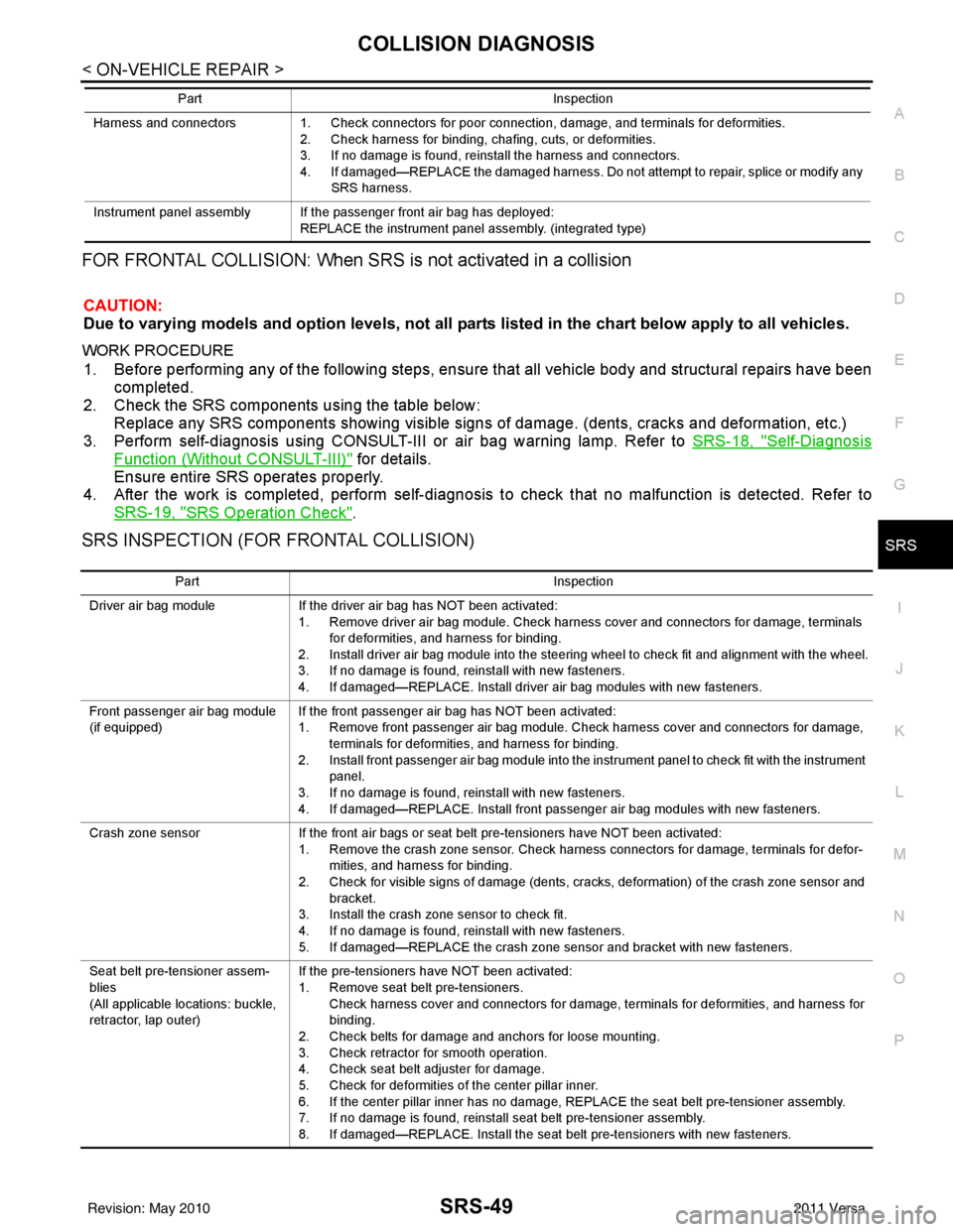
FOR FRONTAL COLLISION: When SRS is not activated in a collision
CAUTION:
Due to varying models and option levels, not all parts listed in the chart below apply to all vehicles.
WORK PROCEDURE
1. Before performing any of the following steps, ensur e that all vehicle body and structural repairs have been
completed.
2. Check the SRS components using the table below: Replace any SRS components showing visible signs of damage. (dents, cracks and deformation, etc.)
3. Perform self-diagnosis using CONSULT-III or air bag warning lamp. Refer to SRS-18, "
Self-Diagnosis
Function (Without CONSULT-III)" for details.
Ensure entire SRS operates properly.
4. After the work is completed, perform self-diagnosis to check that no malfunction is detected. Refer to
SRS-19, "
SRS Operation Check".
SRS INSPECTION (FOR FRONTAL COLLISION)
Harness and connectors 1. Check connectors for poor connection, damage, and terminals for deformities.
2. Check harness for binding, chafing, cuts, or deformities.
3. If no damage is found, reinstall the harness and connectors.
4. If damaged—REPLACE the damaged harness. Do not attempt to repair, splice or modify any SRS harness.
Instrument panel assembly If the passenger front air bag has deployed: REPLACE the instrument panel assembly. (integrated type)
Part
Inspection
Part Inspection
Driver air bag module If the driver air bag has NOT been activated:
1. Remove driver air bag module. Check harness cover and connectors for damage, terminals for deformities, and harness for binding.
2. Install driver air bag module into the steering wheel to check fit and alignment with the wheel.
3. If no damage is found, reinstall with new fasteners.
4. If damaged—REPLACE. Install driver air bag modules with new fasteners.
Front passenger air bag module
(if equipped) If the front passenger air bag has NOT been activated:
1. Remove front passenger air bag module. Check harness cover and connectors for damage,
terminals for deformities, and harness for binding.
2. Install front passenger air bag module into the instrument panel to check fit with the instrument panel.
3. If no damage is found, reinstall with new fasteners.
4. If damaged—REPLACE. Install front passenger air bag modules with new fasteners.
Crash zone sensor If the front air bags or seat belt pre-tensioners have NOT been activated:
1. Remove the crash zone sensor. Check harness connectors for damage, terminals for defor- mities, and harness for binding.
2. Check for visible signs of damage (dents, cracks, deformation) of the crash zone sensor and bracket.
3. Install the crash zone sensor to check fit.
4. If no damage is found, reinstall with new fasteners.
5. If damaged—REPLACE the crash zone sensor and bracket with new fasteners.
Seat belt pre-tensioner assem-
blies
(All applicable locations: buckle,
retractor, lap outer) If the pre-tensioners have NOT been activated:
1. Remove seat belt pre-tensioners.
Check harness cover and connectors for damage, terminals for deformities, and harness for
binding.
2. Check belts for damage and anchors for loose mounting.
3. Check retractor for smooth operation.
4. Check seat belt adjuster for damage.
5. Check for deformities of the center pillar inner.
6. If the center pillar inner has no damage, REPLACE the seat belt pre-tensioner assembly.
7. If no damage is found, reinstall seat belt pre-tensioner assembly.
8. If damaged—REPLACE. Install the seat belt pre-tensioners with new fasteners.
Revision: May 2010 2011 Versa
Page 3684 of 3787
SRS-50
< ON-VEHICLE REPAIR >
COLLISION DIAGNOSIS
For Side and Ro llover Collision
INFOID:0000000005931222
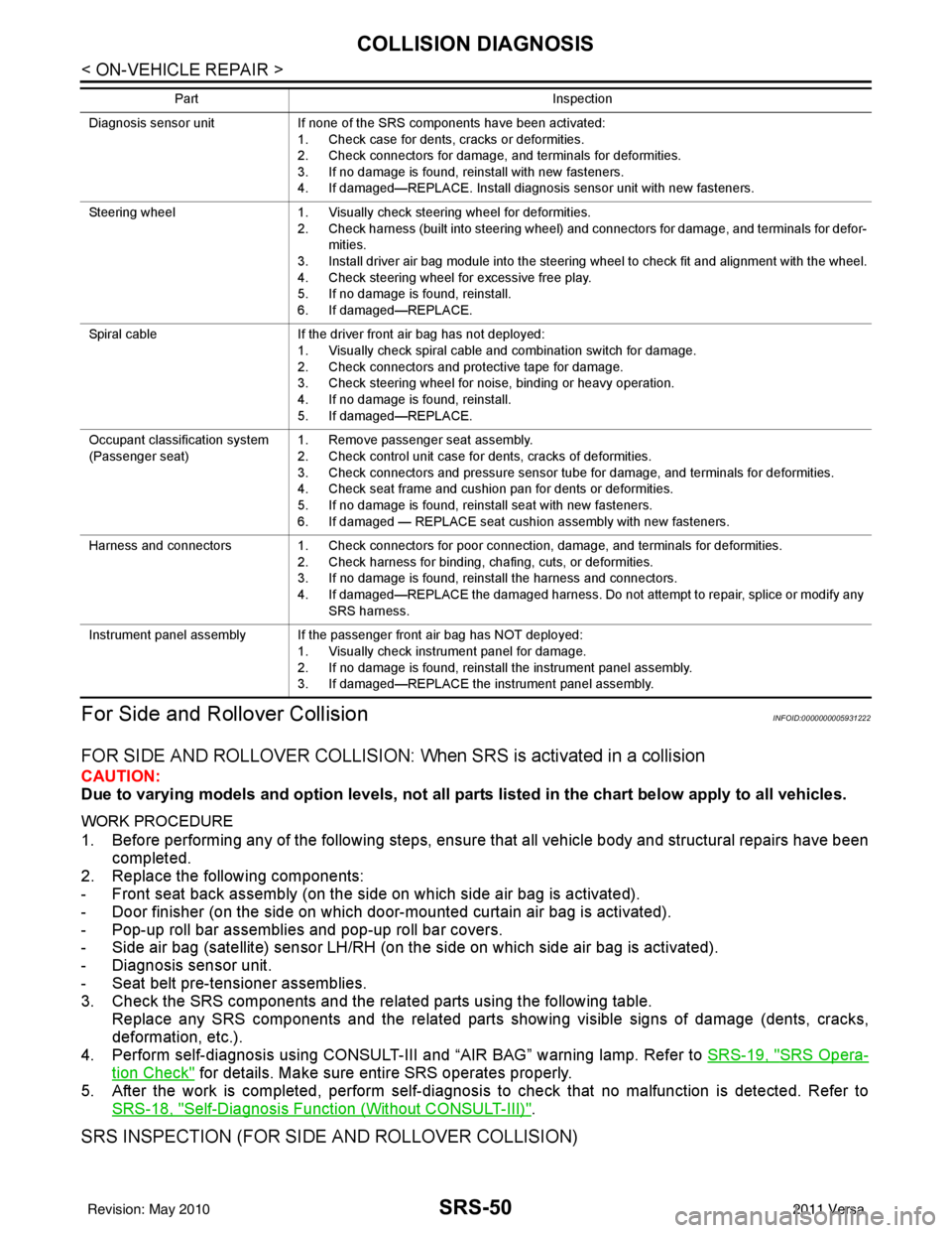
FOR SIDE AND ROLLOVER COLLISION: Wh en SRS is activated in a collision
CAUTION:
Due to varying models and option levels, not all part s listed in the chart below apply to all vehicles.
WORK PROCEDURE
1. Before performing any of the following steps, ensure that all vehicle body and structural repairs have been
completed.
2. Replace the following components:
- Front seat back assembly (on the side on which side air bag is activated).
- Door finisher (on the side on which door-mounted curtain air bag is activated).
- Pop-up roll bar assemblies and pop-up roll bar covers.
- Side air bag (satellite) sensor LH/RH (on the side on which side air bag is activated).
- Diagnosis sensor unit.
- Seat belt pre-tensioner assemblies.
3. Check the SRS components and the related parts using the following table. Replace any SRS components and the related parts showing visible signs of damage (dents, cracks,
deformation, etc.).
4. Perform self-diagnosis using CONSULT-III and “AIR BAG” warning lamp. Refer to SRS-19, "
SRS Opera-
tion Check" for details. Make sure entire SRS operates properly.
5. After the work is completed, perform self-diagnosis to check that no malfunction is detected. Refer to SRS-18, "
Self-Diagnosis Function (Without CONSULT-III)".
SRS INSPECTION (FOR SIDE AND ROLLOVER COLLISION)
Diagnosis sensor unit If none of the SRS components have been activated:
1. Check case for dents, cracks or deformities.
2. Check connectors for damage, and terminals for deformities.
3. If no damage is found, reinstall with new fasteners.
4. If damaged—REPLACE. Install diagnosis sensor unit with new fasteners.
Steering wheel 1. Visually check steering wheel for deformities.
2. Check harness (built into steering wheel) and connectors for damage, and terminals for defor- mities.
3. Install driver air bag module into the steering wheel to check fit and alignment with the wheel.
4. Check steering wheel for excessive free play.
5. If no damage is found, reinstall.
6. If damaged—REPLACE.
Spiral cable If the driver front air bag has not deployed:
1. Visually check spiral cable and combination switch for damage.
2. Check connectors and protective tape for damage.
3. Check steering wheel for noise, binding or heavy operation.
4. If no damage is found, reinstall.
5. If damaged—REPLACE.
Occupant classification system
(Passenger seat) 1. Remove passenger seat assembly.
2. Check control unit case for dents, cracks of deformities.
3. Check connectors and pressure sensor tube for damage, and terminals for deformities.
4. Check seat frame and cushion pan for dents or deformities.
5. If no damage is found, reinstall seat with new fasteners.
6. If damaged — REPLACE seat cushion assembly with new fasteners.
Harness and connectors 1. Check connectors for poor connection, damage, and terminals for deformities.
2. Check harness for binding, chafing, cuts, or deformities.
3. If no damage is found, reinstall the harness and connectors.
4. If damaged—REPLACE the damaged harness. Do not attempt to repair, splice or modify any
SRS harness.
Instrument panel assembly If the passenger front air bag has NOT deployed: 1. Visually check instrument panel for damage.
2. If no damage is found, reinstall the instrument panel assembly.
3. If damaged—REPLACE the instrument panel assembly.
Part
Inspection
Revision: May 2010 2011 Versa
Page 3685 of 3787
COLLISION DIAGNOSISSRS-51
< ON-VEHICLE REPAIR >
C
DE
F
G
I
J
K L
M A
B
SRS
N
O P
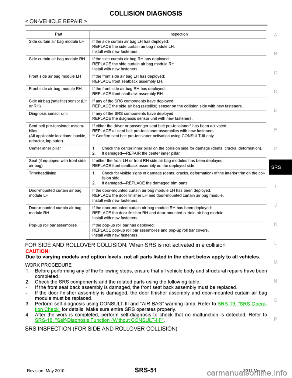
FOR SIDE AND ROLLOVER COLLISION: When SRS is not activated in a collision
CAUTION:
Due to varying models and option levels, not all parts listed in the chart below apply to all vehicles.
WORK PROCEDURE
1. Before performing any of the following steps, ensur e that all vehicle body and structural repairs have been
completed.
2. Check the SRS components and the related parts using the following table.
- If the front seat back assembly is damaged, t he front seat back assembly must be replaced.
- If the door finisher assembly is damaged, the door finisher assembly and door-mounted curtain air bag
module must be replaced.
3. Perform self-diagnosis using CONSULT-III and “AIR BAG” warning lamp. Refer to SRS-19, "
SRS Opera-
tion Check" for details. Make sure entire SRS operates properly.
4. After the work is completed, perform self-diagnosis to check that no malfunction is detected. Refer to
SRS-18, "
Self-Diagnosis Function (Without CONSULT-III)".
SRS INSPECTION (FOR SIDE AND ROLLOVER COLLISION)
Part Inspection
Side curtain air bag module LH If the side curtain air bag LH has deployed: REPLACE the side curtain air bag module LH.
Install with new fasteners.
Side curtain air bag module RH If the side curtain air bag RH has deployed: REPLACE the side curtain air bag module RH.
Install with new fasteners.
Front side air bag module LH If the front side air bag LH has deployed: REPLACE front seatback assembly LH.
Front side air bag module RH If the front side air bag RH has deployed: REPLACE front seatback assembly RH.
Side air bag (satellite) sensor (LH
or RH) If any of the SRS components have deployed:
REPLACE the side air bag (satellite) sensor on the collision side with new fasteners.
Diagnosis sensor unit If any of the SRS components have deployed:
REPLACE the diagnosis sensor unit with new fasteners.
Seat belt pre-tensioner assem-
blies
(All applicable locations: buckle,
retractor, lap outer) If either the driver or passenger seat belt pre-tensioner* has been activated:
REPLACE all seat belt pre-tensioner assemblies with new fasteners.
*: Confirm seat belt pre-tensioner activation using CONSULT-III only.
Center inner pillar 1. Check the center inner pillar on the collision side for damage (dents, cracks, deformation).
2. If damaged—REPAIR the center inner pillar.
Seat (if equipped with front side
air bag) If either the front LH or front RH side air bag modules has been deployed:
REPLACE front seatback assembly on the deployed side.
Trim/headlining 1. Check for visible signs of damage (dents, cracks, deformation) of the interior trim on the col-
lision side.
2. If damaged—REPLACE the damaged trim parts.
Door-mounted curtain air bag
module LH If the door-mounted curtain air bag module LH has been deployed:
REPLACE the door finisher LH and door-mounted curtain air bag module.
Install with new fasteners.
Door-mounted curtain air bag
module RH If the door-mounted curtain air bag module RH has been deployed:
REPLACE the door finisher RH and door-mounted curtain air bag module.
Install with new fasteners.
Pop-up roll bar assemblies If the pop-up roll bar has deployed: REPLACE pop-up roll bar assemblies and pop-up roll bar covers.
Install with new fasteners.
Revision: May 2010 2011 Versa
Page 3686 of 3787

SRS-52
< ON-VEHICLE REPAIR >
COLLISION DIAGNOSIS
PartInspection
Side curtain air bag module LH If the side curtain air bag LH has NOT deployed: 1. Check for visible signs of damage (dents, tears, deformation) of the center pillar on the colli-sion side.
2. If damaged—Remove the side curtain air bag module LH.
3. Check for visible signs of damaged (tears etc.) of the side curtain air bag module LH.
4. Check harness and connectors for damage, and terminals for deformities.
5. If no damage is found, reinstall the side curtain air bag module LH with new fasteners.
6. If damaged—REPLACE the side curtain air bag module LH with new fasteners.
Side curtain air bag module RH If the side curtain air bag RH has NOT deployed: 1. Check for visible signs of damage (dents, tears, deformation) of the center pillar on the colli-
sion side.
2. If damaged—Remove the side curtain air bag module RH.
3. Check for visible signs of damaged (tears etc.) of the side curtain air bag module RH.
4. Check harness and connectors for damage, and terminals for deformities.
5. If no damage is found, reinstall the side curtain air bag module RH with new fasteners.
6. If damaged—REPLACE the side curtain air bag module RH with new fasteners.
Front side air bag module LH If the front LH side air bag has NOT deployed: 1. Check for visible signs of damage (dents, tears, deformation) of the seat back on the collision side.
2. Check harness and connectors for damage, and terminals for deformities.
3. If damaged—REPLACE the front seatback assembly LH.
Front side air bag module RH If the front side air bag RH has NOT deployed: 1. Check for visible signs of damage (dents, tears, deformation) of the seat back on the collision side.
2. Check harness and connectors for damage, and terminals for deformities.
3. If damaged—REPLACE the front seatback assembly RH.
Side air bag (satellite) sensor (LH
or RH) If none of the SRS components have been activated:
1. Remove the side air bag (satellite) sensor (LH or RH) on the collision side. Check harness
connectors for damage, te rminals for deformities, and harness for binding.
2. Check for visible signs of damage (dents, cracks, deformation) of the side air bag (satellite) sensor (LH or RH).
3. Install the side air bag (satellite) sensor (LH or RH) to check fit.
4. If no damage is found, reinstall the side sir bag (satellite) sensor (LH or RH) with new fasten- ers.
5. If damaged—REPLACE the side air bag (satellite) sensor (LH or RH) with new fasteners.
Diagnosis sensor unit If none of the SRS components have been activated:
1. Check case and bracket for dents, cracks or deformities.
2. Check connectors for damage, and terminals for deformities.
3. If no damage is found, reinstall the diagnosis sensor unit with new fasteners.
4. If damaged—REPLACE the diagnosis sensor unit with new fasteners.
Seat belt pre-tensioner assem-
blies
(All applicable locations: buckle,
retractor, lap outer) If the pre-tensioners have NOT been activated:
1. Remove seat belt pre-tensioners.
Check harness cover and connectors for damage, terminals for deformities, and harness for
binding.
2. Check belts for damage and anchors for loose mounting.
3. Check retractor for smooth operation.
4. Check seat belt adjuster for damage.
5. Check for deformities of the center pillar inner.
6. If the center pillar inner has no damage, REPLACE the seat belt pre-tensioner assembly.
7. If no damage is found, reinstall seat belt pre-tensioner assembly.
8. If damaged—REPLACE. Install the seat belt pre-tensioners with new fasteners.
Seat (with front side air bag) If the front LH or front RH side air bag modules have NOT deployed: 1. Visually check the seat on the collision side.
2. Remove the seat on the collision side and check the following for damage and deformities.
- Harness, connectors and terminals
- Frame and recliner (for front and rear seat), and also adjuster and slides (for front seat)
3. If no damage is found, reinstall the seat.
4. If damaged—REPLACE the damaged seat parts using new fasteners. If the front seat back is damaged, the front seat back assembly must be replaced.
Revision: May 2010 2011 Versa
Page 3688 of 3787

STC-1
STEERING
C
DE
F
H I
J
K L
M
SECTION STC
A
B
STC
N
O P
CONTENTS
STEERING CONTROL SYSTEM
EPS
BASIC INSPECTION ....... .............................
3
DIAGNOSIS AND REPAIR WORKFLOW ..... .....3
Work Flow ........................................................... ......3
SYSTEM DESCRIPTION ..............................5
EPS SYSTEM ... .............................................. .....5
System Diagram .................................................. ......5
System Description ...................................................5
Component Parts Location ........................................6
Component Description .............................................6
DIAGNOSIS SYSTEM (EPS CONTROL UNIT)
.....
8
CONSULT-III Function ........................................ ......8
DTC/CIRCUIT DIAGNOSIS ..........................9
C1601 BATTERY POWER SUPPLY ..................9
Description .......................................................... ......9
DTC Logic .................................................................9
Diagnosis Procedure .................................................9
C1604 TORQUE SENSOR .................................11
Description ..............................................................11
DTC Logic ...............................................................11
Diagnosis Procedure ...............................................11
C1606 EPS MOTOR ...........................................13
Description .......................................................... ....13
DTC Logic ...............................................................13
Diagnosis Procedure ...............................................13
Component Inspection ............................................13
C1607, C1608 EPS CONTROL UNIT ................15
Description .......................................................... ....15
DTC Logic ...............................................................15
Diagnosis Procedure ...............................................15
C1609 VEHICLE SPEED SIGNAL .....................16
Description ........................................................... ....16
DTC Logic ................................................................16
Diagnosis Procedure ...............................................16
C1610 ENGINE STATUS SIGNAL ...................17
Description ...............................................................17
DTC Logic ................................................................17
Diagnosis Procedure ...............................................17
U1000 CAN COMM CIRCUIT ...........................18
Description ...............................................................18
DTC Logic ................................................................18
Diagnosis Procedure ...............................................18
EPS WARNING LAMP ......................................19
Description ...............................................................19
Component Function Check ....................................19
Diagnosis Procedure ...............................................19
ECU DIAGNOSIS INFORMATION ..............20
EPS CONTROL UNIT .......................................20
Reference Value .................................................. ....20
Wiring Diagram - ELECTRONICALLY CON-
TROLLED POWER STEERING SYSTEM - ............
22
Fail-Safe .............................................................. ....23
DTC Inspection Priority Chart ..................................24
DTC Index ...............................................................24
SYMPTOM DIAGNOSIS ..............................25
EPS WARNING LAMP DOES NOT TURN ON ...25
Description ........................................................... ....25
Diagnosis Procedure ...............................................25
EPS WARNING LAMP DOES NOT TURN
OFF ....................................................................
26
Description ...............................................................26
Diagnosis Procedure ...............................................26
STEERING WHEEL TURNING FORCE IS
HEAVY OR LIGHT ............................................
27
Revision: May 2010 2011 Versa
Page 3692 of 3787
![NISSAN LATIO 2011 Service Repair Manual EPS SYSTEMSTC-5
< SYSTEM DESCRIPTION > [EPS]
C
D
E
F
H I
J
K L
M A
B
STC
N
O P
SYSTEM DESCRIPTION
EPS SYSTEM
System DiagramINFOID:0000000005931224
System DescriptionINFOID:0000000005931225
• EPS con NISSAN LATIO 2011 Service Repair Manual EPS SYSTEMSTC-5
< SYSTEM DESCRIPTION > [EPS]
C
D
E
F
H I
J
K L
M A
B
STC
N
O P
SYSTEM DESCRIPTION
EPS SYSTEM
System DiagramINFOID:0000000005931224
System DescriptionINFOID:0000000005931225
• EPS con](/manual-img/5/57357/w960_57357-3691.png)
EPS SYSTEMSTC-5
< SYSTEM DESCRIPTION > [EPS]
C
D
E
F
H I
J
K L
M A
B
STC
N
O P
SYSTEM DESCRIPTION
EPS SYSTEM
System DiagramINFOID:0000000005931224
System DescriptionINFOID:0000000005931225
• EPS control unit performs an arithmetical operation on data, such as steering wheel turning force (sensor
signal) from the torque sensor, vehicle speed signal, etc. Then it generates an optimum assist torque signal
to the EPS motor according to the driving condition.
• EPS control unit decreases the output signal to EPS mo tor while extremely using the power steering func-
tion (e.g., full steering) consecutively for protec ting EPS motor and EPS control unit (Overload protection
control). While activating overload protection control, the assist torque gradually decreases, and the steering
wheel turning force becomes heavy. The normal assist torque reactivates by no steering.
• In case of an error in the electrical system, the fail- safe function stops output signals to the EPS motor. Then
the previous state is changed to the manual steering state.
• Self-diagnosis can be done with CONSULT-III.
• EPS control unit will decrease assistance under the following 2 conditions.
- Extensive steering at low speed will cause the ECU and MOTOR to heat up, once temperature reaches crit-
ical point ECU will reduce current to reduce heat up. System will recover as temperature lowers (reduced or
no assistance).
- Holding steering on rack-end (full lock) for 1 second will cause the system to engage rack-end protection. This reduces assistance down to 50% in order to prevent heat up. Assistance is immediately returned to
100% when steering released or turned away from rack-end.
- Communicates the signal from each control unit via CAN communication.
WGIA0187E
Control unit Signal status
ECM Transmits mainly the follow
ing signals to EPS control uni t via CAN communication.
Engine status signal
ABS actuator and electric unit
(control unit) Transmits mainly the follow
ing signals to EPS control uni t via CAN communication.
Vehicle speed signal
Revision: May 2010 2011 Versa