2011 NISSAN CUBE trip computer
[x] Cancel search: trip computerPage 15 of 345
Black plate (11,1)
Model "Z12-D" EDITED: 2010/ 9/ 27
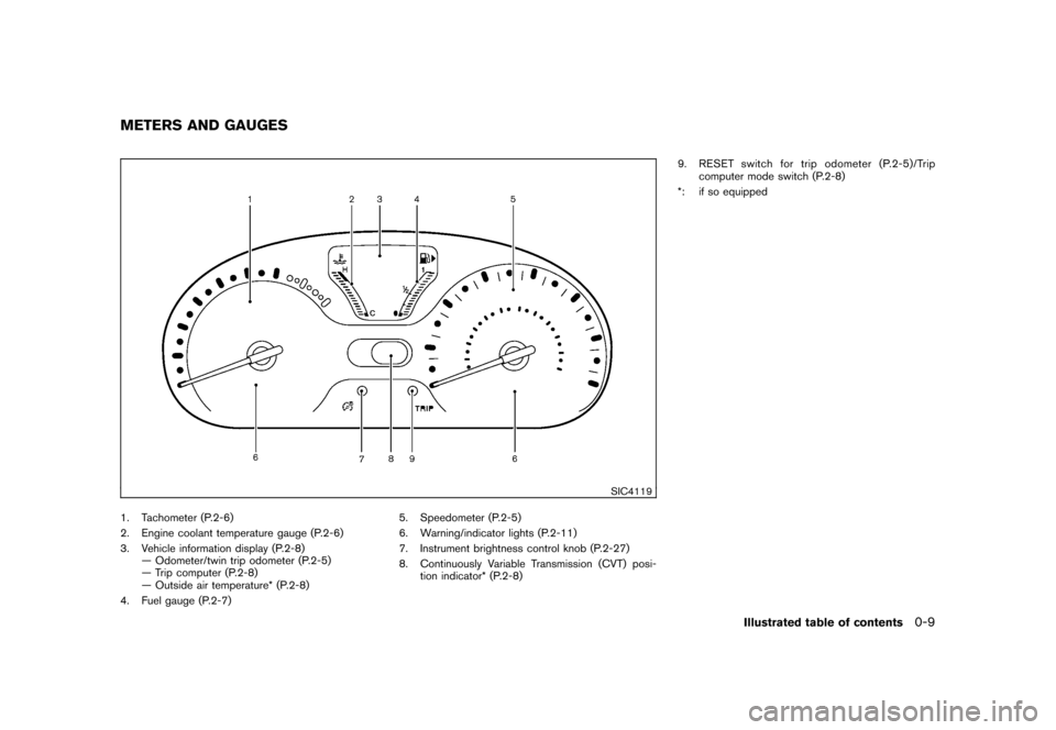
SIC4119
1. Tachometer (P.2-6)
2. Engine coolant temperature gauge (P.2-6)
3. Vehicle information display (P.2-8)— Odometer/twin trip odometer (P.2-5)
— Trip computer (P.2-8)
— Outside air temperature* (P.2-8)
4. Fuel gauge (P.2-7) 5. Speedometer (P.2-5)
6. Warning/indicator lights (P.2-11)
7. Instrument brightness control knob (P.2-27)
8. Continuously Variable Transmission (CVT) posi-
tion indicator* (P.2-8) 9. RESET switch for trip odometer (P.2-5)/Trip
computer mode switch (P.2-8)
*: if so equippedMETERS AND GAUGES
Illustrated table of contents
0-9
Page 75 of 345
Black plate (7,1)
2 Instruments and controls
Model "Z12-D" EDITED: 2010/ 9/ 27
Cockpit............................................................ 2-2
Instrument panel ................................................ 2-3
Meters and gauges ............................................. 2-4
Speedometer and odometer ............................. 2-5
Tachometer ................................................... 2-6
Engine coolant temperature gauge ..................... 2-6
Fuel gauge ................................................... 2-7
Vehicle information display ................................ 2-8
Outside air temperature (if so equipped) .............. 2-8
Continuously Variable Transmission (CVT)
position indicator (if so equipped) ...................... 2-8
Trip computer ................................................ 2-8
Warning/indicator lights and audible reminders ....... 2-11
Checking bulbs ........................................... 2-11
Warning lights ............................................. 2-11
Indicator lights ............................................. 2-16
Audible reminders ........................................ 2-18
Security systems .............................................. 2-18
Vehicle Security System. ................................ 2-18
NISSAN Vehicle Immobilizer System ................. 2-20
Windshield wiper and washer switch .................... 2-21
Rear window wiper and washer switch .................. 2-23
Rear window and outside mirror defroster switch ..... 2-24
Headlight and turn signal switch .......................... 2-24
Headlight switch .......................................... 2-24 Turn signal switch
........................................ 2-27
Fog light switch (if so equipped) ...................... 2-28
Hazard warning flasher switch ............................. 2-28
Horn ............................................................. 2-29
Vehicle Dynamic Control (VDC) OFF switch ........... 2-29
Heated seats (if so equipped) ............................. 2-29
Clock (if so equipped) ....................................... 2-31
Adjusting the time ........................................ 2-31
Resetting the time (Type B) ............................ 2-33
Power outlet ................................................... 2-33
Storage ......................................................... 2-34
Cup holders ................................................ 2-34
Glove box .................................................. 2-36
Rear pillar pocket ......................................... 2-36
Luggage hooks ............................................ 2-37
Utility hooks (if so equipped) ........................... 2-37
Windows ....................................................... 2-38
Power windows ........................................... 2-38
Interior lights ................................................... 2-40
Map lights (if so equipped) ............................. 2-41
Map light control switch (if so equipped) ........... 2-41
Ceiling light ................................................ 2-42
Cargo light (if so equipped) ................................ 2-42
Page 78 of 345

Black plate (76,1)
Model "Z12-D" EDITED: 2010/ 9/ 27
SIC4119
1. Tachometer
2. Engine coolant temperature gauge
3. Vehicle information display— Odometer/twin trip odometer
— Trip computer
— Outside air temperature*
4. Fuel gauge 5. Speedometer
6. Warning/indicator lights
7. Instrument brightness control knob
8. Continuously Variable Transmission (CVT) posi-
tion indicator*
9. RESET switch for trip odometer/Trip computer mode switch *: if so equipped
The needle indicators may move slightly
after the ignition switch is placed in the
OFF or LOCK position. This is not a
malfunction.
METERS AND GAUGES2-4
Instruments and controls
Page 79 of 345
Black plate (77,1)
Model "Z12-D" EDITED: 2010/ 9/ 27
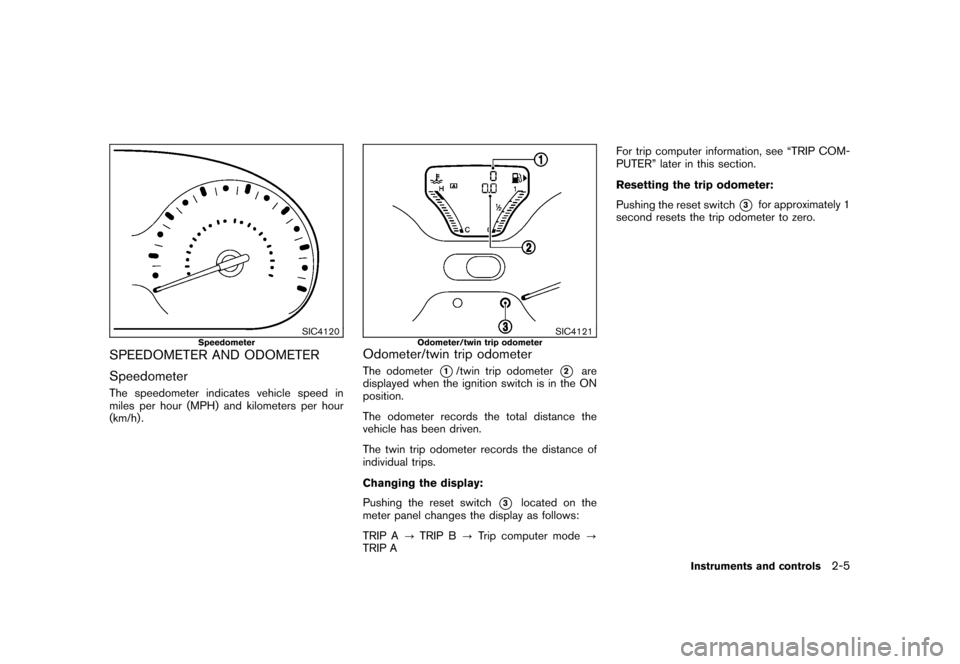
SIC4120
Speedometer
SPEEDOMETER AND ODOMETER
SpeedometerThe speedometer indicates vehicle speed in
miles per hour (MPH) and kilometers per hour
(km/h) .
SIC4121
Odometer/twin trip odometer
Odometer/twin trip odometerThe odometer
*1/twin trip odometer
*2
are
displayed when the ignition switch is in the ON
position.
The odometer records the total distance the
vehicle has been driven.
The twin trip odometer records the distance of
individual trips.
Changing the display:
Pushing the reset switch
*3
located on the
meter panel changes the display as follows:
TRIP A ?TRIP B ?Trip computer mode ?
TRIP A For trip computer information, see “TRIP COM-
PUTER” later in this section.
Resetting the trip odometer:
Pushing the reset switch
*3
for approximately 1
second resets the trip odometer to zero.
Instruments and controls
2-5
Page 80 of 345
Black plate (78,1)
Model "Z12-D" EDITED: 2010/ 9/ 27
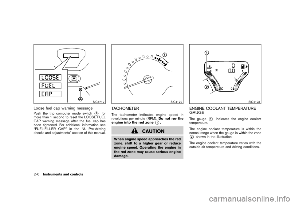
SIC4712
Loose fuel cap warning messagePush the trip computer mode switch
*A
for
more than 1 second to reset the LOOSE FUEL
CAP warning message after the fuel cap has
been tightened. For additional information see
“FUEL-FILLER CAP” in the “3. Pre-driving
checks and adjustments” section of this manual.
SIC4122
TACHOMETERThe tachometer indicates engine speed in
revolutions per minute (RPM) . Do not rev the
engine into the red zone
*1.
CAUTION
When engine speed approaches the red
zone, shift to a higher gear or reduce
engine speed. Operating the engine in
the red zone may cause serious engine
damage.
SIC4123
ENGINE COOLANT TEMPERATURE
GAUGEThe gauge
*1
indicates the engine coolant
temperature.
The engine coolant temperature is within the
normal range when the gauge is within the zone
*2
shown in the illustration.
The engine coolant temperature varies with the
outside air temperature and driving conditions.
2-6
Instruments and controls
Page 82 of 345
Black plate (80,1)
Model "Z12-D" EDITED: 2010/ 9/ 27
SIC4125
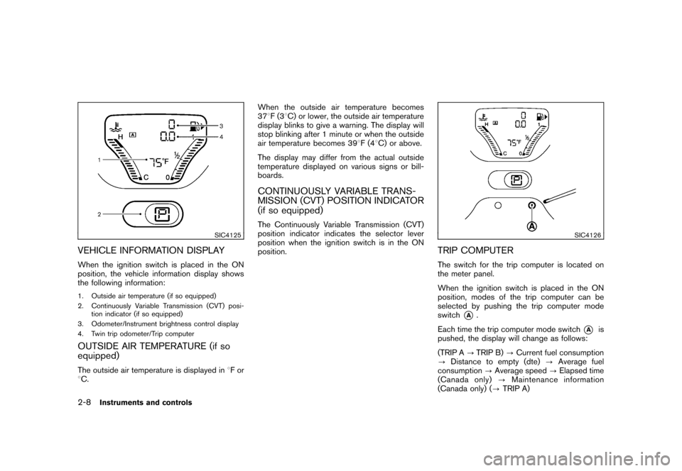
VEHICLE INFORMATION DISPLAYWhen the ignition switch is placed in the ON
position, the vehicle information display shows
the following information:1. Outside air temperature (if so equipped)
2. Continuously Variable Transmission (CVT) posi-tion indicator (if so equipped)
3. Odometer/Instrument brightness control display
4. Twin trip odometer/Trip computerOUTSIDE AIR TEMPERATURE (if so
equipped)The outside air temperature is displayed in 8For
8 C. When the outside air temperature becomes
37
8F(3 8C) or lower, the outside air temperature
display blinks to give a warning. The display will
stop blinking after 1 minute or when the outside
air temperature becomes 39 8F(4 8C) or above.
The display may differ from the actual outside
temperature displayed on various signs or bill-
boards.
CONTINUOUSLY VARIABLE TRANS-
MISSION (CVT) POSITION INDICATOR
(if so equipped)The Continuously Variable Transmission (CVT)
position indicator indicates the selector lever
position when the ignition switch is in the ON
position.
SIC4126
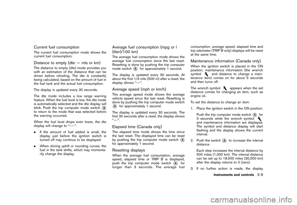
TRIP COMPUTERThe switch for the trip computer is located on
the meter panel.
When the ignition switch is placed in the ON
position, modes of the trip computer can be
selected by pushing the trip computer mode
switch
*A
.
Each time the trip computer mode switch
*A
is
pushed, the display will change as follows:
(TRIP A ?TRIP B) ?Current fuel consumption
? Distance to empty (dte) ?Average fuel
consumption ?Average speed ?Elapsed time
(Canada only) ?Maintenance information
(Canada only) ( ?TRIP A)
2-8
Instruments and controls
Page 83 of 345
Black plate (81,1)
Model "Z12-D" EDITED: 2010/ 9/ 27
Current fuel consumptionThe current fuel consumption mode shows the
current fuel consumption.Distance to empty (dte — mls or km)The distance to empty (dte) mode provides you
with an estimation of the distance that can be
driven before refueling. The dte is constantly
being calculated, based on the amount of fuel in
the fuel tank and the actual fuel consumption.
The display is updated every 30 seconds.
The dte mode includes a low range warning
feature. When the fuel level is low, the dte mode
is automatically selected and the dte display will
blink. Push the trip computer mode switch
*A
to return to the mode that was selected before
the warning occurred.
When the fuel level drops even lower, the dte
display will change to “----”.
.If the amount of fuel added is small, the
display just before the ignition switch is
turned off may continue to be displayed.
. When driving uphill or rounding curves, the
fuel in the tank shifts, which may momenta-
rily change the display.
Average fuel consumption (mpg or l
(liter)/100 km)The average fuel consumption mode shows the
average fuel consumption since the last reset.
Resetting is done by pushing the trip computer
mode switch
*A
for approximately 1 second.
The display is updated every 30 seconds. At
about the first 1/3 mile (500 m) after a reset, the
display shows “---”.
Average speed (mph or km/h)The average speed mode shows the average
vehicle speed since the last reset. Resetting is
done by pushing the trip computer mode switch*A
for approximately 1 second.
The display is updated every 30 seconds. The
first 30 seconds after a reset, the display shows
“---”.
Elapsed time (Canada only)The elapsed time mode shows the time since
the last reset. The displayed time can be reset
by pushing the trip computer mode switch
*A
for approximately 1 second.Resetting displaysWhen the average fuel consumption, average
speed, elapsed time or TRIP B is displayed,
push the trip computer mode switch
*A
for
longer than 3 seconds. The average fuel consumption, average speed, elapsed time and
trip odometer (TRIP B only) displays will be reset
at the same time.
Maintenance information (Canada only)When the ignition switch is placed in the ON
position, maintenance information (the wrench
symbol
and distance to change a main-
tenance item) comes on for about 5 seconds
and then turns off.
The wrench symbol
appears when the set
distance comes for changing an item, such as
engine oil.
To set the distance to change an item:
1. Place the ignition switch in the ON position.
Push the trip computer mode switch
*A
for
3 seconds while the wrench symbol
and maintenance information are displayed.
The symbol and distance display will start
flashing and the display shows the current
interval.
2. Push the switch
*A
to increase the interval
distance.
Each step increases the interval distance by
500 miles (1,000 km) . The interval distance
can be set up to 18,000 miles (30,000 km)
after the display returns to 0 (zero) .
3. If no further action is made, the display
Instruments and controls
2-9
Page 143 of 345
Black plate (141,1)
Model "Z12-D" EDITED: 2010/ 9/ 27
.Do not fill a portable fuel container
in the vehicle or trailer. Static elec-
tricity can cause an explosion of
flammable liquid, vapor or gas in
any vehicle or trailer. To reduce the
risk of serious injury or death when
filling portable fuel containers:
— Always place the container on
the ground when filling.
— Do not use electronic devices when filling.
— Keep the pump nozzle in contact with the container while you are
filling it.
— Use only approved portable fuel containers for flammable liquid.
CAUTION
. If fuel is spilled on the vehicle body,
flush it away with water to avoid
paint damage.
. Insert the cap straight into the fuel-
filler tube, then tighten until the
fuel-filler cap clicks. Failure to tight-
en the fuel-filler cap properly may
cause the
malfunction indicator
light (MIL) to illuminate. If the
light illuminates because the fuel-
filler cap is loose or missing, tighten
or install the cap and continue to
drive the vehicle. The
light
should turn off after a few driving
trips. If the
light does not turn
off after a few driving trips, have the
vehicle inspected by a NISSAN deal-
er.
For additional information, see
“Malfunction Indicator Light (MIL)”
in the “2. Instruments and controls”
section.
. The LOOSE FUEL CAP warning
message will be displayed if the
fuel-filler cap is not properly tigh-
tened. Failure to tighten the fuel-
filler cap properly after the LOOSE
FUEL CAP warning message is dis-
played may cause the
Malfunc-
tion Indicator Light (MIL) to
illuminate.
SIC4712
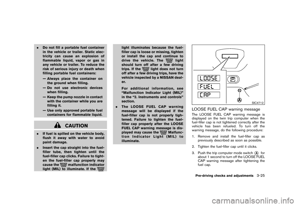
LOOSE FUEL CAP warning messageThe LOOSE FUEL CAP warning message is
displayed on the twin trip computer when the
fuel-filler cap is not tightened correctly after the
vehicle has been refueled. To turn off the
warning message, do the following procedure:
1. Remove and install the fuel-filler cap as previously described as soon as possible.
2. Tighten the fuel-filler cap until it clicks.
3. Push the trip computer mode switch
*A
for
about 1 second to turn off the LOOSE FUEL
CAP warning message after tightening the
fuel cap.
Pre-driving checks and adjustments
3-25