Page 99 of 345

Black plate (97,1)
Model "Z12-D" EDITED: 2010/ 9/ 27
SIC3669
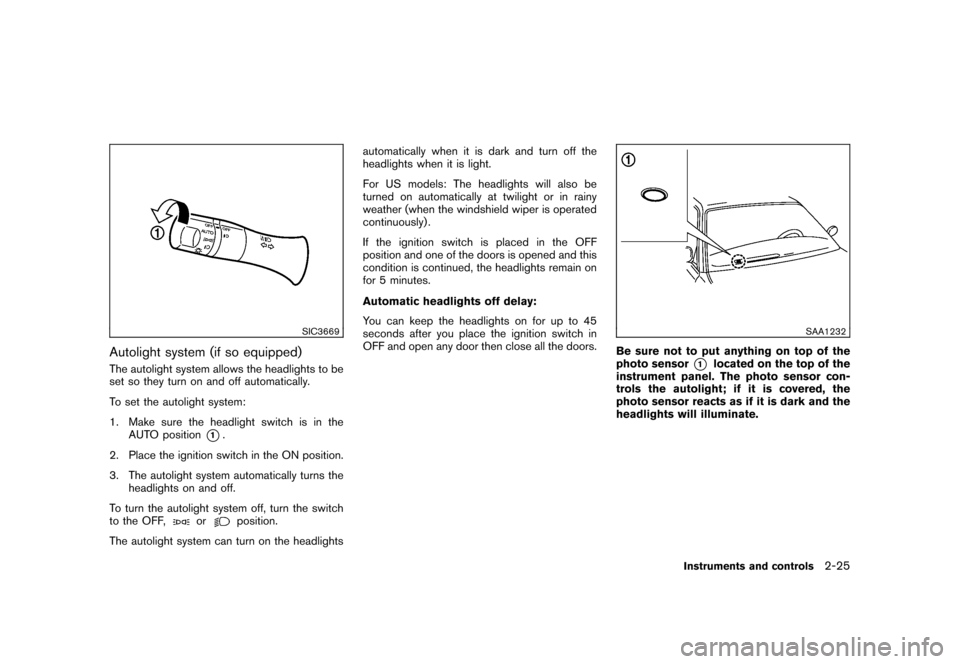
Autolight system (if so equipped)The autolight system allows the headlights to be
set so they turn on and off automatically.
To set the autolight system:
1. Make sure the headlight switch is in theAUTO position
*1.
2. Place the ignition switch in the ON position.
3. The autolight system automatically turns the headlights on and off.
To turn the autolight system off, turn the switch
to the OFF,
or
position.
The autolight system can turn on the headlights automatically when it is dark and turn off the
headlights when it is light.
For US models: The headlights will also be
turned on automatically at twilight or in rainy
weather (when the windshield wiper is operated
continuously) .
If the ignition switch is placed in the OFF
position and one of the doors is opened and this
condition is continued, the headlights remain on
for 5 minutes.
Automatic headlights off delay:
You can keep the headlights on for up to 45
seconds after you place the ignition switch in
OFF and open any door then close all the doors.
SAA1232
Be sure not to put anything on top of the
photo sensor
*1
located on the top of the
instrument panel. The photo sensor con-
trols the autolight; if it is covered, the
photo sensor reacts as if it is dark and the
headlights will illuminate.
Instruments and controls
2-25
Page 101 of 345
Black plate (99,1)
Model "Z12-D" EDITED: 2010/ 9/ 27
SIC4128SIC4129
Instrument brightness controlThe instrument brightness control operates
when the ignition switch is in the ON position.
Push the control knob
*A
to adjust the bright-
ness of the instrument panel lights. The bright-
ness indicator
*B
will be shown briefly in the
vehicle information display when the control is
turned.
When the brightness level reaches the maximum
or minimum, a beep will sound.
SIC3671
TURN SIGNAL SWITCH*1
Turn signal
Move the lever up or down to signal the turning
direction. When the turn is completed, the turn
signals cancel automatically.*2
Lane change signal
To indicate a lane change, move the lever up or
down to the point where lights begin flashing.
Instruments and controls
2-27
Page 107 of 345

Black plate (105,1)
Model "Z12-D" EDITED: 2010/ 9/ 27
5. Push the ENTER SETTING button
*1.
The display will return to the regular clock
display after 5 seconds.
RESETTING THE TIME (Type B)By holding down the MENU button and then
pushing the TUNE or SEEK button, the time will
be reset as follows.
. In case the displayed minute is in the range
of 00 - 29, the hour will stay the same and
the minute will be reset to 00.
. In case the displayed minute is in the range
of 30 - 59, the hour will be advanced by one
hour and the minute will be reset to 00.
For example, if the MENU and TUNE buttons are
pushed while the time is between “8:00” and
“8:29”, the display will be reset to “8:00”. If
pushed while the time is between “8:30” and
“8:59”, the display will be reset to “9:00”. At the
same time the display will return to the previous
audio mode.
SIC4132
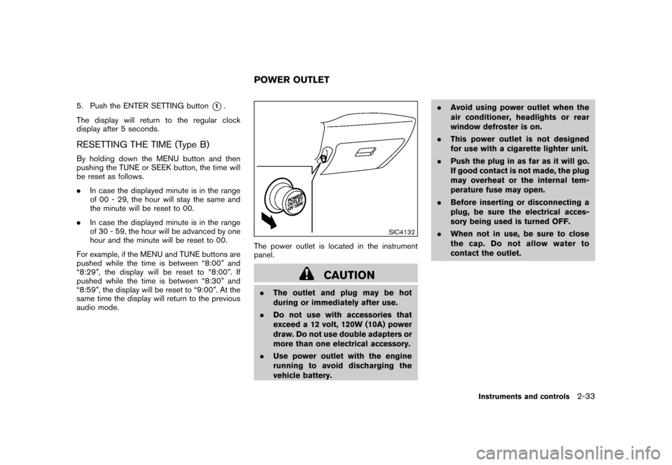
The power outlet is located in the instrument
panel.
CAUTION
. The outlet and plug may be hot
during or immediately after use.
. Do not use with accessories that
exceed a 12 volt, 120W (10A) power
draw. Do not use double adapters or
more than one electrical accessory.
. Use power outlet with the engine
running to avoid discharging the
vehicle battery. .
Avoid using power outlet when the
air conditioner, headlights or rear
window defroster is on.
. This power outlet is not designed
for use with a cigarette lighter unit.
. Push the plug in as far as it will go.
If good contact is not made, the plug
may overheat or the internal tem-
perature fuse may open.
. Before inserting or disconnecting a
plug, be sure the electrical acces-
sory being used is turned OFF.
. When not in use, be sure to close
the cap. Do not allow water to
contact the outlet.POWER OUTLET
Instruments and controls
2-33
Page 108 of 345
Black plate (106,1)
Model "Z12-D" EDITED: 2010/ 9/ 27
CUP HOLDERS
CAUTION
.Avoid abrupt starting and braking
when the cup holder is being used
to prevent spilling the drink. If the
liquid is hot, it can scald you or your
passenger.
. Use only soft cups in the cup holder.
Hard objects can injure you in an
accident.
SIC4133
Driver’s side instrument panel
Front
SIC4134
Center console
STORAGE2-34
Instruments and controls
Page 110 of 345
Black plate (108,1)
Model "Z12-D" EDITED: 2010/ 9/ 27
SIC4138
GLOVE BOX
WARNING
Keep glove box lid closed while driving
to help prevent injury in an accident or a
sudden stop.
To open the glove box, pull the handle.
To close, push the lid in until the lock latches.
SIC4165
WARNING
Do not store objects on the horizontal
surface just above the glove box or on
top of the instrument panel. Objects
can become projectiles and/or interfere
with passenger air bag deployment
causing serious personal injury.
SIC4147
REAR PILLAR POCKET
CAUTION
Do not keep heavy or long objects in
the pocket.
2-36
Instruments and controls
Page 111 of 345
Black plate (109,1)
Model "Z12-D" EDITED: 2010/ 9/ 27
SIC4141
LUGGAGE HOOKS
WARNING
.Do not attach upper tether anchors
to the luggage hooks. The child
restraint will not be properly in-
stalled. Your child could be injured
or killed in a sudden stop or colli-
sion.
. Always make sure that the luggage
is properly secured. Use the suitable
ropes and hooks.
. Unsecured luggage can become dangerous in an accident or sudden
stop.
CAUTION
Do not apply a total load of more than 7
lb (3 kg)
*A
or 22 lb (10 kg)
*B
to a
single hook.
SIC4142
Instrument panel
UTILITY HOOKS (if so equipped)Two removable utility hooks are supplied with
your vehicle. The utility hooks can be attached to
or removed from the holes on the instrument
panel and the rear doors.
CAUTION
Do not apply a total load of more than 3
lb (1.5 kg) to a single hook.
To remove the hook from the hole, pull it straight
up. Do not twist or turn the hooks for
installation or removal.
Instruments and controls
2-37
Page 139 of 345

Black plate (137,1)
Model "Z12-D" EDITED: 2010/ 9/ 27
WARNING
.Make sure the hood is completely
closed and latched before driving.
Failure to do so could cause the
hood to fly open and result in an
accident.
. If you see steam or smoke coming
from the engine compartment, to
avoid injury do not open the hood.
SPA2607
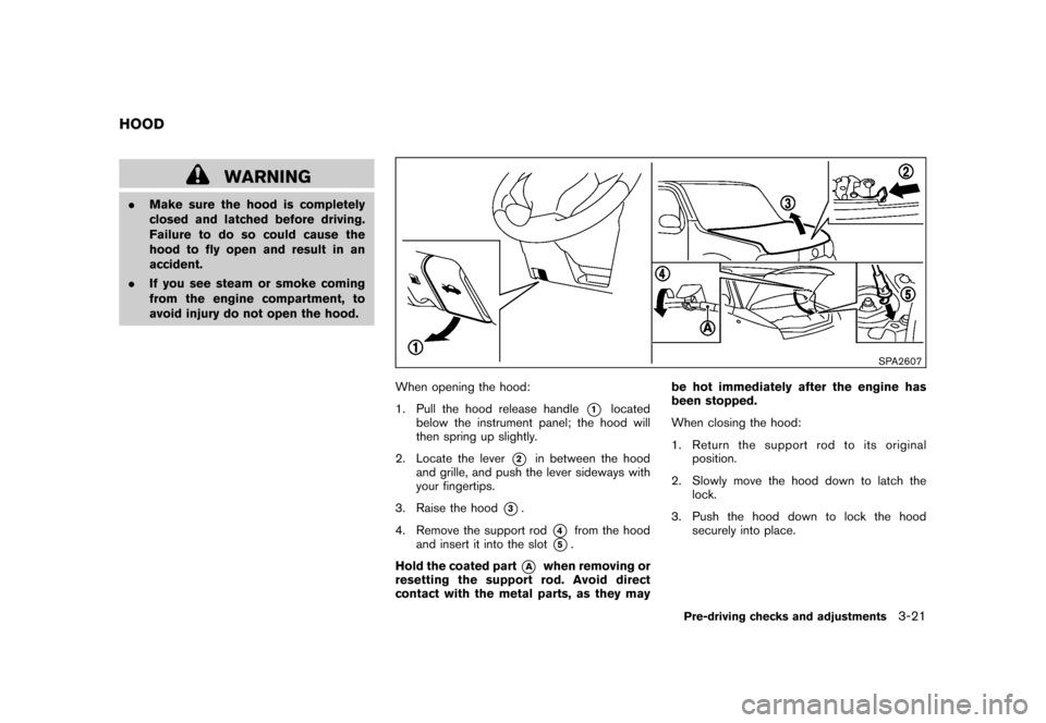
When opening the hood:
1. Pull the hood release handle
*1
located
below the instrument panel; the hood will
then spring up slightly.
2. Locate the lever
*2
in between the hood
and grille, and push the lever sideways with
your fingertips.
3. Raise the hood
*3.
4. Remove the support rod
*4
from the hood
and insert it into the slot
*5.
Hold the coated part
*A
when removing or
resetting the support rod. Avoid direct
contact with the metal parts, as they may be hot immediately after the engine has
been stopped.
When closing the hood:
1. Return the support rod to its original
position.
2. Slowly move the hood down to latch the lock.
3. Push the hood down to lock the hood securely into place.
HOOD
Pre-driving checks and adjustments
3-21
Page 142 of 345

Black plate (140,1)
Model "Z12-D" EDITED: 2010/ 9/ 27
SPA2336
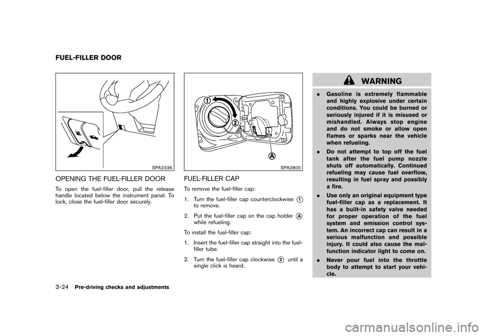
OPENING THE FUEL-FILLER DOORTo open the fuel-filler door, pull the release
handle located below the instrument panel. To
lock, close the fuel-filler door securely.
SPA2800
FUEL-FILLER CAPTo remove the fuel-filler cap:
1. Turn the fuel-filler cap counterclockwise
*1
to remove.
2. Put the fuel-filler cap on the cap holder
*A
while refueling.
To install the fuel-filler cap:
1. Insert the fuel-filler cap straight into the fuel- filler tube.
2. Turn the fuel-filler cap clockwise
*2
until a
single click is heard.
WARNING
. Gasoline is extremely flammable
and highly explosive under certain
conditions. You could be burned or
seriously injured if it is misused or
mishandled. Always stop engine
and do not smoke or allow open
flames or sparks near the vehicle
when refueling.
. Do not attempt to top off the fuel
tank after the fuel pump nozzle
shuts off automatically. Continued
refueling may cause fuel overflow,
resulting in fuel spray and possibly
a fire.
. Use only an original equipment type
fuel-filler cap as a replacement. It
has a built-in safety valve needed
for proper operation of the fuel
system and emission control sys-
tem. An incorrect cap can result in a
serious malfunction and possible
injury. It could also cause the mal-
function indicator light to come on.
. Never pour fuel into the throttle
body to attempt to start your vehi-
cle.
FUEL-FILLER DOOR3-24
Pre-driving checks and adjustments