2011 NISSAN CUBE transmission
[x] Cancel search: transmissionPage 90 of 345
Black plate (88,1)
Model "Z12-D" EDITED: 2010/ 9/ 27
WARNING
If the supplemental air bag warning
light is on, it could mean that the front
air bag, side air bag, curtain air bag
and/or pretensioner systems will not
operate in an accident. To help avoid
injury to yourself or others, have your
vehicle checked by a NISSAN dealer as
soon as possible.INDICATOR LIGHTS
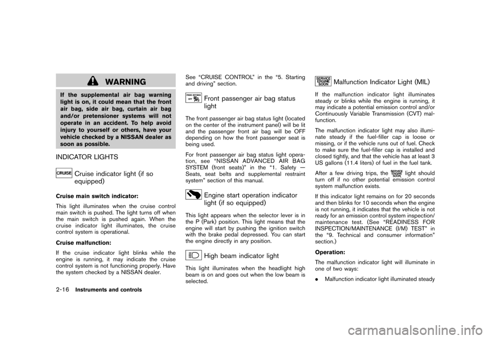
Cruise indicator light (if so
equipped)
Cruise main switch indicator:
This light illuminates when the cruise control
main switch is pushed. The light turns off when
the main switch is pushed again. When the
cruise indicator light illuminates, the cruise
control system is operational.
Cruise malfunction:
If the cruise indicator light blinks while the
engine is running, it may indicate the cruise
control system is not functioning properly. Have
the system checked by a NISSAN dealer.See “CRUISE CONTROL” in the “5. Starting
and driving” section.
Front passenger air bag status
light
The front passenger air bag status light (located
on the center of the instrument panel) will be lit
and the passenger front air bag will be OFF
depending on how the front passenger seat is
being used.
For front passenger air bag status light opera-
tion,see“NISSANADVANCEDAIRBAG
SYSTEM (front seats)” in the “1. Safety —
Seats, seat belts and supplemental restraint
system” section of this manual.
Engine start operation indicator
light (if so equipped)
This light appears when the selector lever is in
the P (Park) position. This light means that the
engine will start by pushing the ignition switch
with the brake pedal depressed. You can start
the engine directly in any position.
High beam indicator light
This light illuminates when the headlight high
beam is on and goes out when the low beam is
selected.
Malfunction Indicator Light (MIL)
If the malfunction indicator light illuminates
steady or blinks while the engine is running, it
may indicate a potential emission control and/or
Continuously Variable Transmission (CVT) mal-
function.
The malfunction indicator light may also illumi-
nate steady if the fuel-filler cap is loose or
missing, or if the vehicle runs out of fuel. Check
to make sure the fuel-filler cap is installed and
closed tightly, and that the vehicle has at least 3
US gallons (11.4 liters) of fuel in the fuel tank.
After a few driving trips, the
light should
turn off if no other potential emission control
system malfunction exists.
If this indicator light remains on for 20 seconds
and then blinks for 10 seconds when the engine
is not running, it indicates that the vehicle is not
ready for an emission control system inspection/
maintenance test. (See “READINESS FOR
INSPECTION/MAINTENANCE (I/M) TEST” in
the “9. Technical and consumer information”
section.)
Operation:
The malfunction indicator light will illuminate in
one of two ways:
. Malfunction indicator light illuminated steady
2-16
Instruments and controls
Page 91 of 345
Black plate (89,1)
Model "Z12-D" EDITED: 2010/ 9/ 27
— An emission control system and/or CVT
malfunction has been detected. Check the
fuel-filler cap. If the LOOSE FUEL CAP
warning message is displayed on the twin
trip odometer, if the fuel-filler cap is loose or
missing, tighten or install the cap and
continue to drive the vehicle. The
light
should turn off after a few driving trips. If the
light does not turn off after a few
driving trips, have the vehicle inspected by a
NISSAN dealer. You do not need to have
your vehicle towed to the dealer.
. Malfunction indicator light blinking — An
engine misfire has been detected which may
damage the emission control system.
To reduce or avoid emission control system
damage:
a) Do not drive at speeds above 45 MPH (72 km/h) .
b) Avoid hard acceleration or deceleration.
c) Avoid steep uphill grades.
d) If possible, reduce the amount of cargo being hauled or towed.
The malfunction indicator light may stop
blinking and remain illuminated.
Have the vehicle inspected by a NISSAN
dealer. You do not need to have your vehicle towed to the dealer.
CAUTION
Continued vehicle operation without
having the emission control system
and/or CVT system checked and re-
paired as necessary could lead to poor
driveability, reduced fuel economy, and
possible damage to the emission con-
trol system.
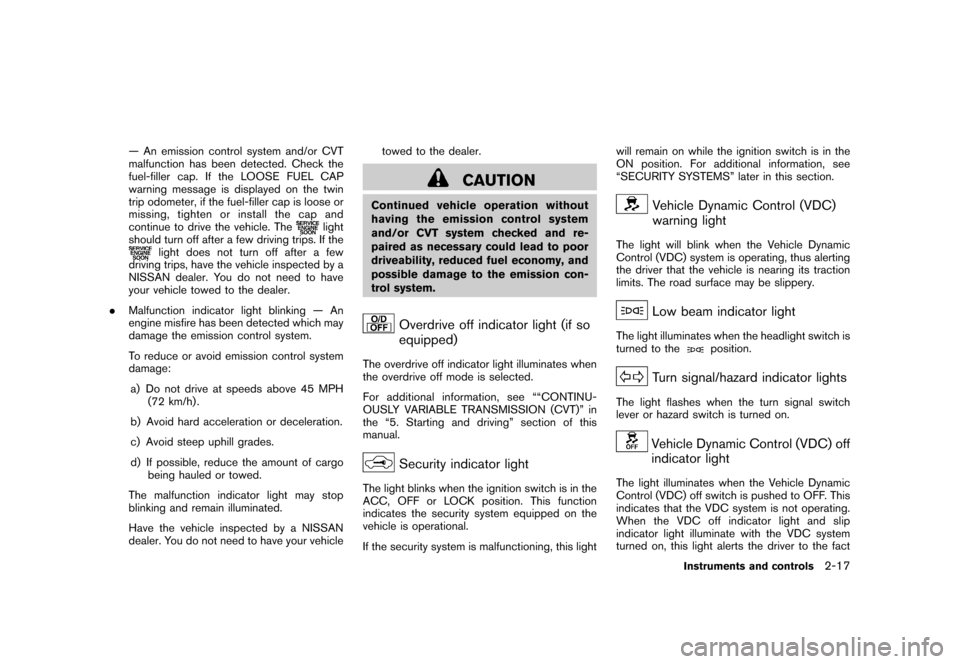
Overdrive off indicator light (if so
equipped)
The overdrive off indicator light illuminates when
the overdrive off mode is selected.
For additional information, see ““CONTINU-
OUSLY VARIABLE TRANSMISSION (CVT)” in
the “5. Starting and driving” section of this
manual.
Security indicator light
The light blinks when the ignition switch is in the
ACC, OFF or LOCK position. This function
indicates the security system equipped on the
vehicle is operational.
If the security system is malfunctioning, this lightwill remain on while the ignition switch is in the
ON position. For additional information, see
“SECURITY SYSTEMS” later in this section.
Vehicle Dynamic Control (VDC)
warning light
The light will blink when the Vehicle Dynamic
Control (VDC) system is operating, thus alerting
the driver that the vehicle is nearing its traction
limits. The road surface may be slippery.
Low beam indicator light
The light illuminates when the headlight switch is
turned to the
position.
Turn signal/hazard indicator lights
The light flashes when the turn signal switch
lever or hazard switch is turned on.
Vehicle Dynamic Control (VDC) off
indicator light
The light illuminates when the Vehicle Dynamic
Control (VDC) off switch is pushed to OFF. This
indicates that the VDC system is not operating.
When the VDC off indicator light and slip
indicator light illuminate with the VDC system
turned on, this light alerts the driver to the fact
Instruments and controls
2-17
Page 213 of 345
Black plate (211,1)
Model "Z12-D" EDITED: 2010/ 9/ 27
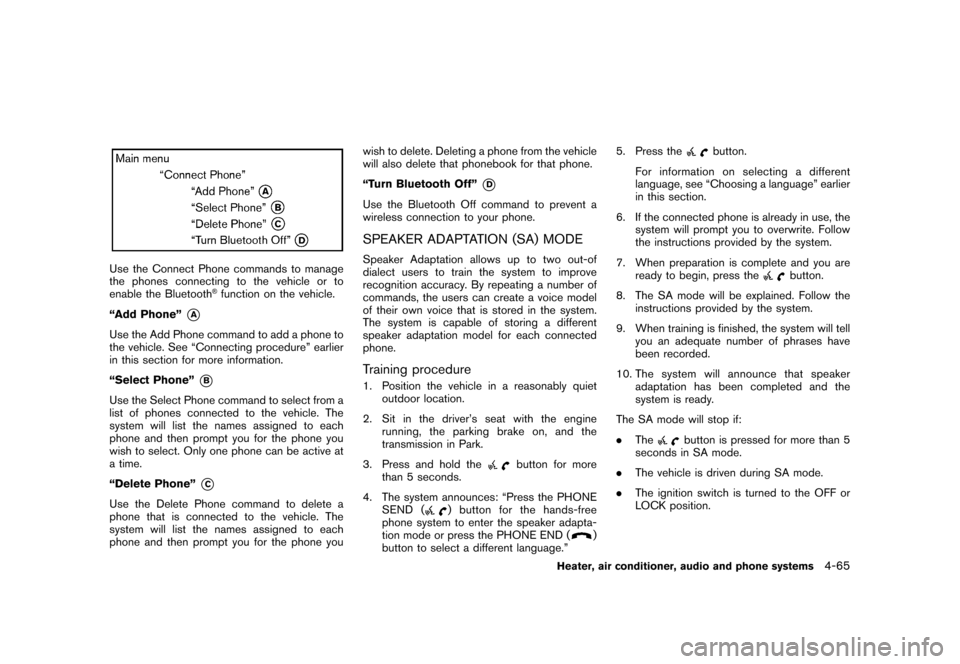
Use the Connect Phone commands to manage
the phones connecting to the vehicle or to
enable the Bluetooth
®function on the vehicle.
“Add Phone”
*A
Use the Add Phone command to add a phone to
the vehicle. See “Connecting procedure” earlier
in this section for more information.
“Select Phone”
*B
Use the Select Phone command to select from a
list of phones connected to the vehicle. The
system will list the names assigned to each
phone and then prompt you for the phone you
wish to select. Only one phone can be active at
a time.
“Delete Phone”
*C
Use the Delete Phone command to delete a
phone that is connected to the vehicle. The
system will list the names assigned to each
phone and then prompt you for the phone you wish to delete. Deleting a phone from the vehicle
will also delete that phonebook for that phone.
“Turn Bluetooth Off”
*D
Use the Bluetooth Off command to prevent a
wireless connection to your phone.SPEAKER ADAPTATION (SA) MODESpeaker Adaptation allows up to two out-of
dialect users to train the system to improve
recognition accuracy. By repeating a number of
commands, the users can create a voice model
of their own voice that is stored in the system.
The system is capable of storing a different
speaker adaptation model for each connected
phone.Training procedure1. Position the vehicle in a reasonably quiet
outdoor location.
2. Sit in the driver’s seat with the engine running, the parking brake on, and the
transmission in Park.
3. Press and hold the
button for more
than 5 seconds.
4. The system announces: “Press the PHONE SEND (
) button for the hands-free
phone system to enter the speaker adapta-
tion mode or press the PHONE END (
)
button to select a different language.” 5. Press the
button.
For information on selecting a different
language, see “Choosing a language” earlier
in this section.
6. If the connected phone is already in use, the system will prompt you to overwrite. Follow
the instructions provided by the system.
7. When preparation is complete and you are ready to begin, press the
button.
8. The SA mode will be explained. Follow the instructions provided by the system.
9. When training is finished, the system will tell you an adequate number of phrases have
been recorded.
10. The system will announce that speaker adaptation has been completed and the
system is ready.
The SA mode will stop if:
. The
button is pressed for more than 5
seconds in SA mode.
. The vehicle is driven during SA mode.
. The ignition switch is turned to the OFF or
LOCK position.
Heater, air conditioner, audio and phone systems
4-65
Page 217 of 345
Black plate (16,1)
5 Starting and driving
Model "Z12-D" EDITED: 2010/ 9/ 27
Precautions when starting and driving..................... 5-2
Exhaust gas (carbon monoxide) ......................... 5-2
Three-way catalyst .......................................... 5-2
Tire Pressure Monitoring System (TPMS) ............. 5-3
Avoiding collision and rollover ........................... 5-5
Off-road recovery ........................................... 5-5
Rapid air pressure loss .................................... 5-6
Drinking alcohol/drugs and driving ...................... 5-6
Ignition switch
(models without Intelligent Key system) ................... 5-7
Continuously Variable Transmission (CVT) ............ 5-7
Manual Transmission (MT) ................................ 5-8
Key positions ................................................ 5-8
Push-button ignition switch
(models with Intelligent Key system) ....................... 5-9
Operating range for engine start function ............. 5-9
Push-button ignition switch operation. ............... 5-10
Steering lock (if so equipped) ......................... 5-10
Push-button ignition switch positions ................ 5-10
Emergency engine shut off ............................. 5-11
Intelligent Key battery discharge ...................... 5-11
Before starting the engine .................................. 5-12
Starting the engine ........................................... 5-12
Models without Intelligent Key system ............... 5-12
Models with Intelligent Key system ................... 5-13Driving the vehicle
............................................ 5-14
Continuously Variable Transmission (CVT) .......... 5-14
Manual Transmission (MT) .............................. 5-18
Parking brake .................................................. 5-20
Cruise control (if so equipped) ............................ 5-21
Precautions on cruise control .......................... 5-21
Cruise control operations ............................... 5-21
Break-in schedule ............................................ 5-23
Increasing fuel economy .................................... 5-23
Parking/parking on hills ...................................... 5-24
Electric power steering system ............................ 5-25
Brake system .................................................. 5-26
Braking precautions ...................................... 5-26
Anti-lock Braking System (ABS) ...................... 5-26
Vehicle Dynamic Control (VDC) system ................. 5-28
Cold weather driving ......................................... 5-29
Freeing a frozen door lock .............................. 5-29
Anti-freeze .................................................. 5-29
Battery ...................................................... 5-29
Draining of coolant water ............................... 5-29
Tire equipment ............................................ 5-30
Special winter equipment ............................... 5-30
Driving on snow or ice .................................. 5-30
Engine block heater (if so equipped) ................. 5-30
Page 224 of 345
Black plate (222,1)
Model "Z12-D" EDITED: 2010/ 9/ 27
When the ignition switch cannot be turned to
the LOCK position:
1. Move the selector lever to the P (Park)position.
2. Turn the ignition switch slightly in the ON direction.
3. TurntheignitionswitchtotheLOCK position.
4. Remove the key.
If the ignition switch is turned to the LOCK
position, the selector lever cannot be moved
from the P (Park) position. The selector lever can
be moved if the ignition switch is in the ON
position with the foot brake pedal depressed.
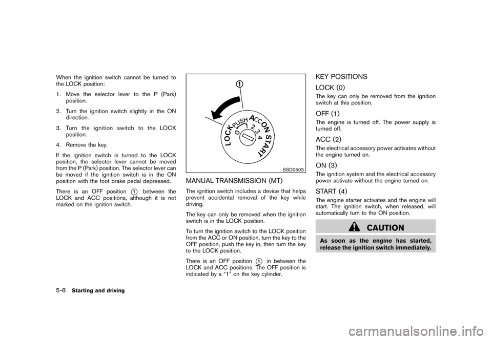
There is an OFF position
*1
between the
LOCK and ACC positions, although it is not
marked on the ignition switch.
SSD0503
MANUAL TRANSMISSION (MT)The ignition switch includes a device that helps
prevent accidental removal of the key while
driving.
The key can only be removed when the ignition
switch is in the LOCK position.
To turn the ignition switch to the LOCK position
from the ACC or ON position, turn the key to the
OFF position, push the key in, then turn the key
to the LOCK position.
There is an OFF position
*1
in between the
LOCK and ACC positions. The OFF position is
indicated by a “1” on the key cylinder.
KEY POSITIONS
LOCK (0)The key can only be removed from the ignition
switch at this position.OFF (1)The engine is turned off. The power supply is
turned off.ACC (2)The electrical accessory power activates without
the engine turned on.ON (3)The ignition system and the electrical accessory
power activate without the engine turned on.START (4)The engine starter activates and the engine will
start. The ignition switch, when released, will
automatically turn to the ON position.
CAUTION
As soon as the engine has started,
release the ignition switch immediately.
5-8
Starting and driving
Page 228 of 345
Black plate (226,1)
Model "Z12-D" EDITED: 2010/ 9/ 27
chime sounds. The engine will start.
After step 3 is performed, when the ignition
switch is pushed without depressing the brake
pedal, the ignition switch position will change to
ACC.
NOTE:
. When the ignition switch is pushed to
the ACC or ON position or the engine is
started by the above procedures, the
Intelligent Key system warning light
may blink in yellow even if the Intelli-
gent Key is inside the vehicle. This is
not a malfunction. To stop the warning
light from blinking, touch the ignition
switch with the Intelligent Key again.
. If the Intelligent Key system warning
light in the meter is blinking in green,
replace the battery as soon as possible.
(See “KEY BATTERY REPLACEMENT”
in the “8. Maintenance and do-it-your-
self” section.) .
Make sure the area around the vehicle is
clear.
. Check fluid levels such as engine oil, cool-
ant, brake fluid, and window washer fluid as
frequently as possible, or at least whenever
you refuel.
. Check that all windows and lights are clean.
. Visually inspect tires for their appearance
and condition. Also check tires for proper
inflation.
. Lock all doors.
. Position seat and adjust head restraints.
. Adjust inside and outside mirrors.
. Fasten seat belts and ask all passengers to
do likewise.
. Check the operation of warning lights when
the ignition switch is placed in the ON
position. (See “WA RNING/INDICATOR
LIGHTS AND AUDIBLE REMINDERS” in
the “2. Instruments and controls” section.)
MODELS WITHOUT INTELLIGENT KEY
SYSTEM1. Apply the parking brake.
2. Continuously Variable Transmission
(CVT) models:
Move the selector lever to the P (Park) or N
(Neutral) position. (P is recommended.)
The starter is designed so that it does not
operate unless the selector lever is in either
of the above positions.
Manual Transmission (MT) models:
Move the shift lever to the N (Neutral)
position. Depress the clutch pedal fully to
the floor.
The starter is designed not to operate unless
the clutch pedal is fully depressed.
3. Crank the engine with your foot off the
accelerator pedal by turning the ignition
switch to START. Release the switch when
the engine starts. If the engine starts, but
fails to run, repeat the above procedure.
— If the engine is very hard to start in extremely cold weather or when restart-
ing, depress the accelerator pedal a little
(approximately 1/3 to the floor) and hold
it and then crank the engine. Release the
accelerator pedal when the engine
BEFORE STARTING THE ENGINE STARTING THE ENGINE
5-12
Starting and driving
Page 230 of 345
Black plate (228,1)
Model "Z12-D" EDITED: 2010/ 9/ 27
4.Warm-up
Allow the engine to idle for at least 30
seconds after starting. Do not race the
engine while warming it up. Drive at
moderate speed for a short distance first,
especially in cold weather. In cold weather,
keep the engine running for a minimum of 2 -
3 minutes before shutting it off. Starting and
stopping the engine over a short period of
time may make the vehicle more difficult to
start.
When racing the engine up to 4,000 rpm or
more under no load condition, the engine
will enter the fuel cut mode.
5. To stop the engine, move the selector lever to the P (Park) position, and push the
ignition switch to the OFF position.
CONTINUOUSLY VARIABLE TRANS-
MISSION (CVT)The Continuously Variable Transmission (CVT)
in your vehicle is electronically controlled to
produce maximum power and smooth operation.
The recommended operating procedures for this
transmission are shown on the following pages.
Follow these procedures for maximum vehicle
performance and driving enjoyment.
Engine power may be automatically re-
duced to protect the CVT if the engine
speed increases quickly when driving on
slippery roads or while being tested on
some dynamometers.Starting the vehicle1. After starting the engine, fully depress thefoot brake pedal before moving the selector
lever out of the P (Park) position.
This CVT is designed so that the foot
brake pedal must be depressed before
shifting from P (Park) to any driving
position while the ignition switch is in
the ON position.
The selector lever cannot be moved out
of the P (Park) position and into any of
the other positions if the ignition
switch is placed in the LOCK, OFF or
ACC position or if the key is removed. 2. Keep the foot brake pedal depressed, push
the selector lever button and move the
selector lever to a driving position.
3. Release the parking brake and foot brake pedal, and then gradually start the vehicle in
motion.
WARNING
.Do not depress the accelerator
pedal while shifting from P (Park)
or N (Neutral) to R (Reverse) , D
(Drive) or L (Low) . Always depress
the brake pedal until shifting is
completed. Failure to do so could
cause you to lose control and have
an accident.
. Cold engine idle speed is high, so
use caution when shifting into a
forward or reverse gear before the
engine has warmed up.
. Never shift to P (Park) or R (Re-
verse) while vehicle is moving. Fail-
ure to do so could cause you to lose
control and have an accident.
DRIVING THE VEHICLE
5-14
Starting and driving
Page 232 of 345
Black plate (230,1)
Model "Z12-D" EDITED: 2010/ 9/ 27
position.
CAUTION
To prevent transmission damage, move
the selector lever to the P (Park) or R
(Reverse) position only when the vehi-
cle is completely stopped.
P (Park):
Use this selector position when the vehicle is
parked or when starting the engine. Make sure
the vehicle is completely stopped. The brake
pedal must be depressed and the selector
lever button pushed in to move the selec-
tor lever from N (Neutral) or any drive
position to P (Park) . Apply the parking brake.
When parking on a hill, apply the parking brake
first, then move the selector lever to the P (Park)
position.
R (Reverse):
Use this position to back up. Make sure the
vehicle is completely stopped before selecting
the R (Reverse) position. The brake pedal
must be depressed and the selector lever
button pushed in to move the selector
lever from P (Park) , N (Neutral) or any
driving position to R (Reverse) . N (Neutral):
Neither forward nor reverse gear is engaged.
The engine can be started in this position. You
may shift to N (Neutral) and restart a stalled
engine while the vehicle is moving.
D (Drive):
Use this position for all normal forward driving.
L (Low):
Use this position for maximum engine braking on
steep downhill gradients/climbing steep slopes
and whenever approaching sharp bends. Do not
use the L (Low) position in any other circum-
stances.
SSD0863
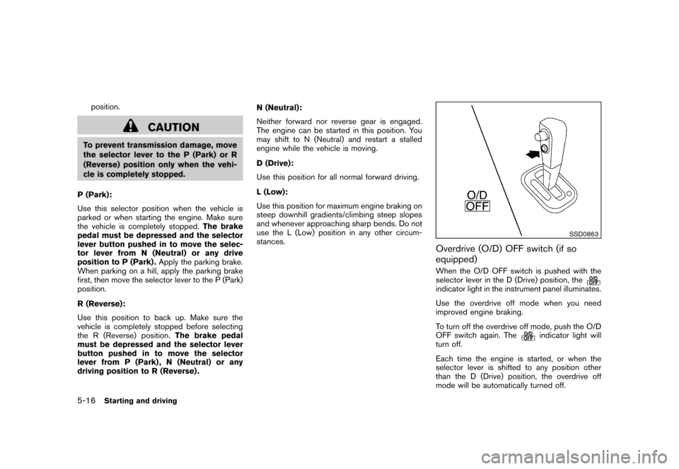
Overdrive (O/D) OFF switch (if so
equipped)When the O/D OFF switch is pushed with the
selector lever in the D (Drive) position, theindicator light in the instrument panel illuminates.
Use the overdrive off mode when you need
improved engine braking.
To turn off the overdrive off mode, push the O/D
OFF switch again. The
indicator light will
turn off.
Each time the engine is started, or when the
selector lever is shifted to any position other
than the D (Drive) position, the overdrive off
mode will be automatically turned off.
5-16
Starting and driving