Page 17 of 489
1. Battery (P. 8-14)
2. Fuse/fusible link box (P. 8-23)
3. Transmission dipstick (P. 8-11)
4. Engine oil filler cap (P. 8-9)
5. Brake fluid reservoir (P. 8-12)
6. Windshield-washer fluid reservoir(P. 8-13)
7. Air cleaner (P. 8-17)
8. Drive belt location (P.8-16)
9. Radiator cap (P. 8-7)
10. Power steering fluid reservoir (P. 8-12)
11. Engine oil dipstick (P. 8-9)
12. Engine coolant reservoir (P. 8-7)
See the page number indicated in paren-
theses for operating details.
Page 169 of 489

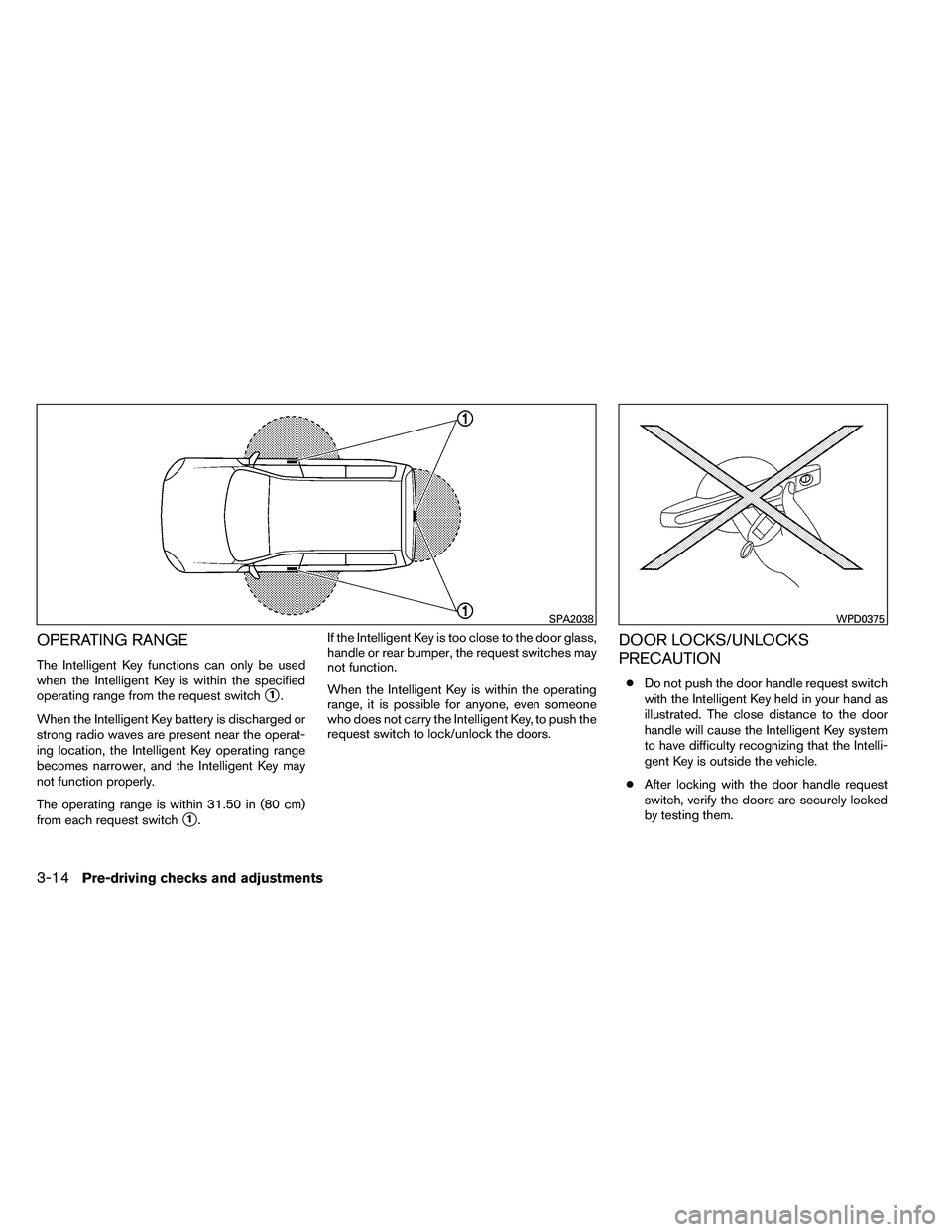
OPERATING RANGE
The Intelligent Key functions can only be used
when the Intelligent Key is within the specified
operating range from the request switch
�1.
When the Intelligent Key battery is discharged or
strong radio waves are present near the operat-
ing location, the Intelligent Key operating range
becomes narrower, and the Intelligent Key may
not function properly.
The operating range is within 31.50 in (80 cm)
from each request switch
�1. If the Intelligent Key is too close to the door glass,
handle or rear bumper, the request switches may
not function.
When the Intelligent Key is within the operating
range, it is possible for anyone, even someone
who does not carry the Intelligent Key, to push the
request switch to lock/unlock the doors.
DOOR LOCKS/UNLOCKS
PRECAUTION
●
Do not push the door handle request switch
with the Intelligent Key held in your hand as
illustrated. The close distance to the door
handle will cause the Intelligent Key system
to have difficulty recognizing that the Intelli-
gent Key is outside the vehicle.
● After locking with the door handle request
switch, verify the doors are securely locked
by testing them.
Page 347 of 489

When the ignition switch cannot be turned to-
ward the LOCK position when the Intelligent Key
is in range, proceed as follows:1. Move the shift selector into the P (Park) position.
2. Turn the ignition switch slightly in the ON direction.
3. Turn the switch toward the LOCK position.
The shift selector can be moved from the P
(Park) position if the ignition switch is in
the ON position and the foot brake pedal is
depressed.
There is an OFF position in between LOCK and
ACC, although it does not show on the ignition
switch. When the ignition switch is OFF, the
steering wheel is not locked (for models with a
steering wheel lock mechanism) .
In order for the steering wheel to be locked, it
must be turned about 1/6 of a turn counterclock-
wise from the straight up position.
To lock the steering wheel, turn the ignition
switch to the LOCK position. To unlock the
steering wheel, push the ignition switch in
and turn it gently while rotating the steer-
ing wheel slightly right and left. If the battery of the vehicle equipped with
the Intelligent Key system is discharged,
the ignition switch cannot be turned from
the LOCK position, even using the me-
chanical key.
Operating range
The Intelligent Key functions can only be used
when the Intelligent Key is within the specified
operating range.
When the Intelligent Key battery is almost dis-
charged or strong radio waves are present near
the operating location, the Intelligent Key sys-
tem’s operating range becomes narrower and
may not function properly.
If the Intelligent Key is within the operating range,
it is possible for anyone, even someone who does
not carry the Intelligent Key, to turn the ignition
switch to start the engine.
Page 355 of 489

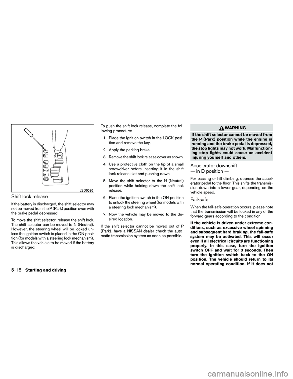
Shift lock release
If the battery is discharged, the shift selector may
not be moved from the P (Park) position even with
the brake pedal depressed.
To move the shift selector, release the shift lock.
The shift selector can be moved to N (Neutral) .
However, the steering wheel will be locked un-
less the ignition switch is placed in the ON posi-
tion (for models with a steering lock mechanism) .
This allows the vehicle to be moved if the battery
is discharged.To push the shift lock release, complete the fol-
lowing procedure:
1. Place the ignition switch in the LOCK posi- tion and remove the key.
2. Apply the parking brake.
3.
Remove the shift lock release cover as shown.
4. Use a protective cloth on the tip of a small screwdriver before inserting it in the shift
lock release slot and pushing down.
5. Move the shift selector to the N (Neutral) position while holding down the shift lock
release.
6. Place the ignition switch in the ON position to unlock the steering wheel (for models with
a steering lock mechanism) .
7. Now the vehicle may be moved to the de- sired location.
If the shift selector cannot be moved out of P
(Park) , have a NISSAN dealer check the auto-
matic transmission system as soon as possible.
Page 403 of 489
1. Battery
2. Fuse/fusible link box
3. Transmission dipstick
4. Engine oil filler cap
5. Brake fluid reservoir
6. Windshield-washer fluid reservoir
7. Air cleaner
8. Drive belt location
9. Radiator cap
10. Power steering fluid reservoir
11. Engine oil dipstick
12. Engine coolant reservoir
NOTE:
Engine cover removed for clarity.
Page 477 of 489

Additional information concerning motor
vehicle safety may be obtained from Trans-
port Canada’s Road Safety Information
Centre at 1-800-333-0371 or online at
www.tc.gc.ca/roadsafety (English speak-
ers) or www.tc.gc.ca/securiteroutiere
(French speakers) .
To notify NISSAN of any safety concerns
please contact our Consumer Information
Centre toll free at 1-800-387-0122.
Due to legal requirements in some states and
Canadian Provinces, your vehicle may be re-
quired to be in what is called the “ready condi-
tion” for an Inspection/Maintenance (I/M) test of
the emission control system.
The vehicle is set to the “ready condition” when it
is driven through certain driving patterns. Usually,
the ready condition can be obtained by ordinary
usage of the vehicle.
If a powertrain system component is repaired or the
battery is disconnected, the vehicle may be reset to
a “not ready” condition. Before taking the I/M test,
check the vehicle’s inspection/maintenance test
readiness condition. Place the ignition switch in the
ON position without starting the engine. If the
Malfunction Indicator Light (MIL) comes on steady
for 20 seconds and then blinks for 10 seconds , the
I/M test condition is “not ready”. If the MIL does not
blink after 20 seconds, the I/M test condition is
“ready”. Contact a NISSAN dealer to set the “ready
condition” or to prepare the vehicle for testing.
This vehicle is equipped with an Event Data Re-
corder (EDR) . The main purpose of an EDR is to
record, in certain crash or near crash-like situa-
tions, such as an air bag deployment or hitting a
road obstacle, data that will assist in understand-
ing how a vehicle’s systems performed. The EDR
is designed to record data related to vehicle
dynamics and safety systems for a short period of
time, typically 30 seconds or less. The EDR in this
vehicle is designed to record such data as:● How various systems in your vehicle were
operating;
● Whether or not the driver and passenger
safety belts were buckled/fastened;
● How far (if at all) the driver was depressing
the accelerator and/or brake pedal; and,
● How fast the vehicle was traveling.
● Sounds are not recorded.
These data can help provide a better understand-
ing of the circumstances in which crashes and
injuries occur. NOTE: EDR data are recorded by
your vehicle only if a nontrivial crash situation
occurs; no data are recorded by the EDR under
normal driving conditions and no personal data
(e.g. name, gender, age and crash location) are
recorded. However, other parties, such as law
enforcement, could combine the EDR data with
READINESS FOR INSPECTION/
MAINTENANCE (I/M) TEST EVENT DATA RECORDERS (EDR)
9-34Technical and consumer information