Page 14 of 377

E10 type petrol
E00203200019
The petrol engines
are compatible with E10 type
petrol (containing 10 % ethanol) conforming to Eu-
ropean standards EN 228. CAUTION
l
Do not use more than 10 %
concentration
of ethanol (grain alcohol) by volume.
Use
of more than 10 % concentration
may lead to damage to your vehicle fuel
system, engine, engine sensors and ex-
haust system. Filling the fuel tank
E00200201767 WARNING
l When handling
fuel,
comply with the safe-
ty regulations displayed by garages and
filling stations.
l Before removing the fuel tank filler tube
cap, be sure to get rid of your body’s stat-
ic electricity by touching a metal part of
the car or fuel pump. Any static electrici-
ty on your body could create a spark that
ignites fuel vapour.
l Perform the whole refueling process
(opening the fuel tank filler door, remov-
ing the fuel tank filler tube cap, etc.) by
yourself. Do not let any other person
come near the fuel tank filler. If you al-
lowed a person to help you and that per-
son was carrying static electricity, fuel va-
pour could be ignited.
l Do not move away from the fuel tank fill-
er door until refueling is finished. If you
moved away and did something else (for
example, cleaning your windscreen) part-
way through the refueling process, you
could pick up a fresh charge of static elec-
tricity.
l If the fuel tank filler tube cap must be re-
placed, use only a MITSUBISHI
MOTORS original part.
Fuel tank capacity
3-door models: 69 litres
5-door models: 88 litres Refueling
1.Before filling with fuel, stop the engine.
2. The
fuel tank filler is located on the rear
right side of your vehicle.
Open the fuel tank filler door with the re-
lease lever located below the instrument panel.
LHD General information
03 RHD
OBKE12E1
Page 287 of 377

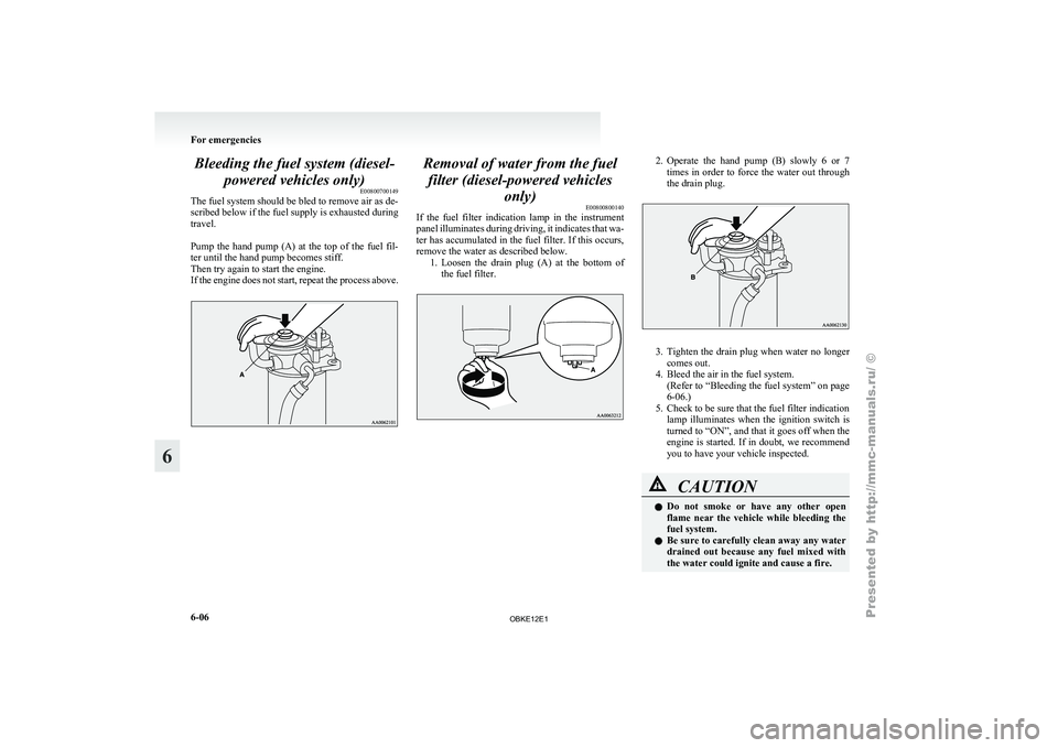
Bleeding the fuel system (diesel-
powered vehicles only) E00800700149
The fuel system should be bled to remove air as de-
scribed below if the fuel supply is exhausted during
travel.
Pump the hand
pump (A) at the top of the fuel fil-
ter until the hand pump becomes stiff.
Then try again to start the engine.
If the engine does not start, repeat the process above. Removal of water from the fuel
filter (diesel-powered vehicles only) E00800800140
If the fuel
filter indication lamp in the instrument
panel illuminates during driving, it indicates that wa-
ter has accumulated in the fuel filter. If this occurs,
remove the water as described below. 1. Loosen the drain plug (A) at the bottom ofthe fuel filter. 2. Operate the hand pump (B) slowly 6 or 7
times in order to force the water out through
the drain plug. 3. Tighten the drain plug when water no longer
comes out.
4. Bleed the air in the fuel system.
(Refer
to “Bleeding the fuel system” on page
6-06.)
5. Check to be sure that the fuel filter indication lamp illuminates when the ignition switch is
turned to “ON”, and that it goes off when the
engine is started. If in doubt, we recommend
you to have your vehicle inspected. CAUTION
l
Do not
smoke
or have any other open
flame near the vehicle while bleeding the
fuel system.
l Be sure to carefully clean away any water
drained out because any fuel mixed with
the water could ignite and cause a fire. For emergencies
6-06
6
OBKE12E1
Page 328 of 377

No. Symbol Electrical sys-
tem Capacity
27 Starter motor
10 A
28 — — —
29 — Spare fuse 20 A
30 — Spare fuse 10 A
31 — Spare fuse 30 A
32 — Spare fuse 25 A l
Some fuses
may not be installed on your ve-
hicle, depending on the vehicle model or spec-
ifications.
l The table above shows the main equipment
corresponding to each fuse.
The fuse block does not contain spare 7.5 A
and 15 A fuses. If a fuse of one of these ca-
pacities blows, replace it temporarily by bor-
rowing the one that matches from:
7.5 A: Outside rear-view mirrors
15 A: Cigarette lighter
Replace the borrowed fuse as soon as possible. Engine compartment fuse location table
E01008000639
Engine compartment fuse location (Type A) No. Symbol Electrical sys-
tem Capacity
1 Alternator
140 A*1
2 Fuse (+B)
60 A*1
3 Ignition switch
40 A*1
4 Electric win-
dow control 30 A
*1
5 Engine control
20 A*1
6 Fuel pump 20 A
*1 : Fusible link
*2 : Vehicles without discharge headlamps
*3 : Vehicles with discharge headlamps No. Symbol Electrical sys-
tem Capacity
7 Rear heater 25 A
8 Accessory sock-
et 25 A
9 Fuel line heater
25 A
10 Condenser fan
motor 25 A
11 Rear air condi-
tioning 20 A
12 Horn (Theft-
alarm system) 15 A Wiper de-icer
13 Horn 10 A
14 Automatic
transmission 20 A
15 Hazard warning
flasher 10 A
16 Stop lamps 15 A
17 Radio 10 A
18 Room lamp 15 A
19 Air condition-
ing 10 A
20 Front fog lamps 15 A
*1 : Fusible link
*2 : Vehicles without discharge headlamps
*3 : Vehicles with discharge headlamps Maintenance
8-21 8
OBKE12E1