Page 625 of 714
7-28 Vehicle care and maintenance
7
Tire inflation pressures
N00939300815
Proper tire inflation pressure is essential for the safe and satis-
factory operation of your vehicle. The wrong tire pressure will
cause problems in three major areas:
�Safety
Too little pressure increases flexing in the tire and can
cause tire failure. Too much pressure can cause a tire to
lose its ability to cushion shock. Objects on the road and
potholes could then cause tire damage that may result in
tire failure.
�Economy
The wrong tire pressure can cause uneven wear patterns in
the tire tread. These abnormal wear patterns will reduce
the tread life, and the tire will have to be replaced sooner.
Too little pressure also makes it harder for the tire to roll,
and this uses up more fuel.
�Ride comfort and vehicle stability
The superior riding experience built into your vehicle
partly depends on the correct tire pressure. Too much
pressure gives an uncomfortable and jarring ride. Too lit-
tle pressure feels as if your vehicle is slow to respond.
Unequal tire pressures can make steering your vehicle
uneven and unpredictable.
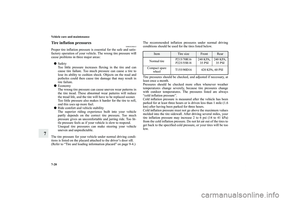
The tire pressure for your vehicle under normal driving condi-
tions is listed on the placard attached to the driver’s door sill.
(Refer to “Tire and loading information placard” on page 9-4.)The recommended inflation pressures under normal driving
conditions should be used for the tires listed below.
Tire pressures should be checked, and adjusted if necessary, at
least once a month.
Pressures should be checked more often whenever weather
temperatures change severely, because tire pressures change
with outdoor temperatures. The pressures listed are always
“cold inflation pressure”.
Cold inflation pressure is measured after the vehicle has been
parked for at least three hours or is driven less than 1 mile (1.6
km) after having been parked for three hours.
Cold inflation pressure must not go above the maximum values
molded into the tire sidewall. After driving several miles, your
tire inflation pressure may increase 2 to 6 psi (14 to 41 kPa)
from the cold inflation pressure. Do not let air out of the tires to
get back to the specified cold pressure, or your tires will be too
low.
Item
Tire size
Front
Rear
Normal tireP215/70R16
P225/55R18240 KPA,
35 PSI240 KPA,
35 PSI
Compact spare
wheelT155/90D16 420 KPA, 60 PSI
BK0122500US.book 28 ページ 2010年5月12日 水曜日 午前11時11分
Page 628 of 714

Vehicle care and maintenance
7-31
7
Tire rotation
N00939900488
To even out the wear on your tires and make them last longer,
Mitsubishi Motors Corporation recommends that you rotate
your tires at the mileage listed in the “WARRANTY AND
MAINTENANCE MANUAL”.
However, the timing for tire rotation may vary according to
your vehicle condition, road surface conditions, and your own
personal driving habits. Any time you notice unusual wear,
rotate your tires as soon as possible.
When rotating tires, check for uneven wear, damage, and wheel
alignment. Abnormal wear is usually caused by a wrong tire
pressure, wheels that are not aligned properly, wheels that are
out-of-balance, or severe braking.
Check with an authorized Mitsubishi Motors dealer or a repair
facility of your choice to find out the reason for uneven tread
wear.
The first tire rotation is the most important one. It will allow all
your tires to wear evenly.
CAUTION
!�A compact spare tire can be installed temporarily in
place of a tire that has been removed during the tire
rotation. However, it must not be included in the
regular tire rotation sequence.Tires that do not have arrows showing rotation direction
Tires that have arrows showing rotation directionFront
Front
BK0122500US.book 31 ページ 2010年5月12日 水曜日 午前11時11分
Page 635 of 714
7-38 Vehicle care and maintenance
7
Ball joint, steering linkage seals, drive shaft boots
N00941800093
Check the following parts for damage and grease leaks:
�Ball joint boots of the suspension and steering linkage
�Bellows on both ends of the drive shaftDrive belt (for generator, power steering pump,
air conditioning compressor)
N00941900270
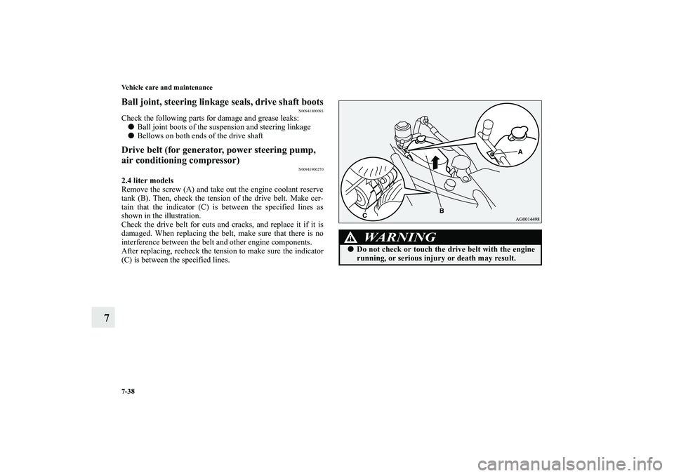
2.4 liter models
Remove the screw (A) and take out the engine coolant reserve
tank (B). Then, check the tension of the drive belt. Make cer-
tain that the indicator (C) is between the specified lines as
shown in the illustration.
Check the drive belt for cuts and cracks, and replace it if it is
damaged. When replacing the belt, make sure that there is no
interference between the belt and other engine components.
After replacing, recheck the tension to make sure the indicator
(C) is between the specified lines.
WA R N I N G
!�Do not check or touch the drive belt with the engine
running, or serious injury or death may result.
BK0122500US.book 38 ページ 2010年5月12日 水曜日 午前11時11分
Page 636 of 714
Vehicle care and maintenance
7-39
7
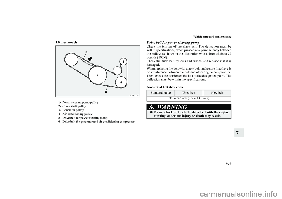
3.0 liter models
Drive belt for power steering pumpCheck the tension of the drive belt. The deflection must be
within specifications, when pressed at a point halfway between
the pulleys as shown in the illustration with a force of about 22
pounds (100N).
Check the drive belt for cuts and cracks, and replace it if it is
damaged.
When replacing the belt with a new belt, make sure that there is
no interference between the belt and other engine components.
Then, check the tension of the belt at the designated point. The
deflection must be within the specifications.
Amount of belt deflection
1- Power steering pump pulley
2- Crank shaft pulley
3- Generator pulley
4- Air conditioning pulley
5- Drive belt for power steering pump
6- Drive belt for generator and air conditioning compressor
Standard value
Used belt
New belt
.33 to .72 inch (8.5 to 18.3 mm)
WA R N I N G
!�Do not check or touch the drive belt with the engine
running, or serious injury or death may result.
BK0122500US.book 39 ページ 2010年5月12日 水曜日 午前11時11分
Page 637 of 714
7-40 Vehicle care and maintenance
7
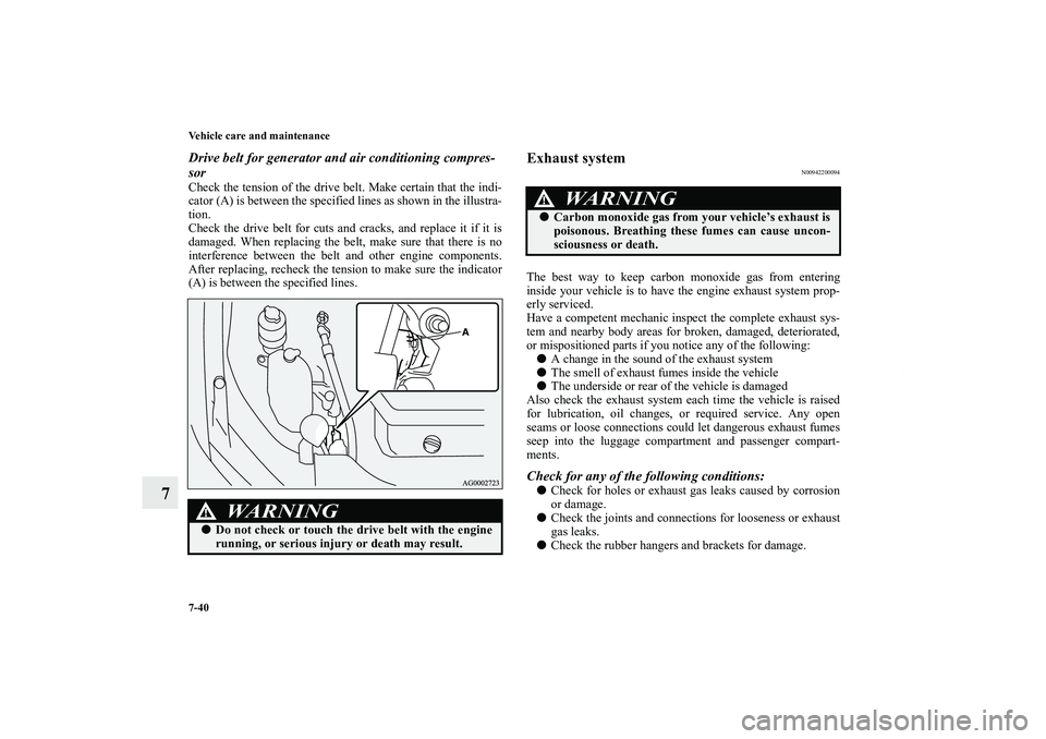
Drive belt for generator and air conditioning compres-
sorCheck the tension of the drive belt. Make certain that the indi-
cator (A) is between the specified lines as shown in the illustra-
tion.
Check the drive belt for cuts and cracks, and replace it if it is
damaged. When replacing the belt, make sure that there is no
interference between the belt and other engine components.
After replacing, recheck the tension to make sure the indicator
(A) is between the specified lines.
Exhaust system
N00942200094
The best way to keep carbon monoxide gas from entering
inside your vehicle is to have the engine exhaust system prop-
erly serviced.
Have a competent mechanic inspect the complete exhaust sys-
tem and nearby body areas for broken, damaged, deteriorated,
or mispositioned parts if you notice any of the following:
�A change in the sound of the exhaust system
�The smell of exhaust fumes inside the vehicle
�The underside or rear of the vehicle is damaged
Also check the exhaust system each time the vehicle is raised
for lubrication, oil changes, or required service. Any open
seams or loose connections could let dangerous exhaust fumes
seep into the luggage compartment and passenger compart-
ments.Check for any of the following conditions:�Check for holes or exhaust gas leaks caused by corrosion
or damage.
�Check the joints and connections for looseness or exhaust
gas leaks.
�Check the rubber hangers and brackets for damage.
WA R N I N G
!�Do not check or touch the drive belt with the engine
running, or serious injury or death may result.
WA R N I N G
!�Carbon monoxide gas from your vehicle’s exhaust is
poisonous. Breathing these fumes can cause uncon-
sciousness or death.
BK0122500US.book 40 ページ 2010年5月12日 水曜日 午前11時11分
Page 644 of 714

Vehicle care and maintenance
7-47
7
No.
Symbol
Electrical system
Capacity
1 Front fog lights 15 A
2Engine7.5 A
3 Automatic transaxle 20 A
4 Horn 10 A
5 Alternator 7.5 A
6 Headlight washer 20 A
7 Air conditioning 10 A
8ETV/Oil cooler fan
(Twin Clutch SST)15 A
9 Security horn 20 A
10 Wiper deicer 15 A
11 — — —
12 Power gate 30 A
13 Daytime running lights 10 A
14Headlight
(high beam) (left)10 A
15Headlight
(high beam) (right)10 A
16Headlight
(low beam)
(left)Discharge 20 A
17Headlight
(low beam)
(right)Discharge 20 A
18Headlight
(low beam)
(left)Halogen 10 A
19Headlight
(low beam)
(right)Halogen 10 A
20 ENG/POWER 10 A
21 Ignition coil 10 A
22ENG/POWER 20 A
Fuel line heater 25 A
23 Fuel pump 15 A
24 Starter 30 A*
25 — — —
26 Anti-lock braking system 40 A*
27 Anti-lock braking system 30 A*
28Air conditioning condenser fan
motor30 A*
29 Radiator fan 40 A*
30 IOD IOD 30 A
31 Audio amplifier 30 ANo.
Symbol
Electrical system
Capacity
BK0122500US.book 47 ページ 2010年5月12日 水曜日 午前11時11分
Page 693 of 714
9-2 Specifications
9Vehicle labeling
N01147400625
Keep a record of the chassis number and vehicle identification
number. Such information will assist police if your vehicle is
stolen.1 - Vehicle emission control information labelThe vehicle emission control information label is affixed on the
underside of the engine hood.2 - Vehicle identification number plateThe vehicle identification number is stamped on the plate riv-
eted to the left front corner of the dashboard. It is visible from
outside of the vehicle through the windshield.3 - Air conditioning labelThe air conditioning label is affixed on the inside panel of the
engine hood.
4 - Vehicle information code plateThe vehicle information code plate is located on the front pas-
senger door sill.
BK0122500US.book 2 ページ 2010年5月12日 水曜日 午前11時11分
Page 702 of 714
Specifications
9-11
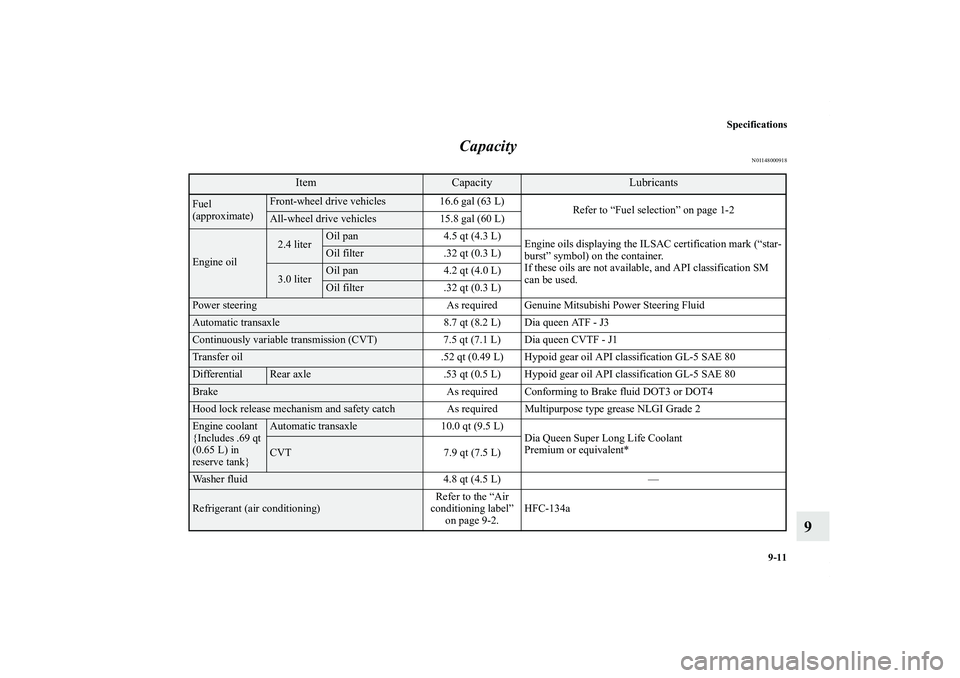
9 Capacity
N01148000918
Item
Capacity
Lubricants
Fuel
(approximate)
Front-wheel drive vehicles 16.6 gal (63 L)
Refer to “Fuel selection” on page 1-2All-wheel drive vehicles 15.8 gal (60 L)
Engine oil
2.4 liter
Oil pan 4.5 qt (4.3 L)
Engine oils displaying the ILSAC certification mark (“star-
burst” symbol) on the container.
If these oils are not available, and API classification SM
can be used.Oil filter .32 qt (0.3 L)
3.0 liter
Oil pan 4.2 qt (4.0 L)Oil filter .32 qt (0.3 L)
Power steering As required Genuine Mitsubishi Power Steering FluidAutomatic transaxle 8.7 qt (8.2 L) Dia queen ATF - J3Continuously variable transmission (CVT) 7.5 qt (7.1 L) Dia queen CVTF - J1Transfer oil .52 qt (0.49 L) Hypoid gear oil API classification GL-5 SAE 80Differential
Rear axle .53 qt (0.5 L) Hypoid gear oil API classification GL-5 SAE 80
Brake As required Conforming to Brake fluid DOT3 or DOT4Hood lock release mechanism and safety catch As required Multipurpose type grease NLGI Grade 2Engine coolant
{Includes .69 qt
(0.65 L) in
reserve tank}
Automatic transaxle 10.0 qt (9.5 L)
Dia Queen Super Long Life Coolant
Premium or equivalent*CVT 7.9 qt (7.5 L)
Washer fluid 4.8 qt (4.5 L) —Refrigerant (air conditioning)Refer to the “Air
conditioning label”
on page 9-2.HFC-134a
BK0122500US.book 11 ページ 2010年5月12日 水曜日 午前11時11分