Page 204 of 714
Features and controls
3-89
3 Steering wheel lock
N00512500166
[For vehicles equipped with the Free-hand Advanced Secu-
rity Transmitter (F.A.S.T.-key).]
For information on operations for vehicles equipped with the
Free-hand Advanced Security Transmitter (F.A.S.T.-key), refer
to “Free-hand Advanced Security Transmitter (F.A.S.T.-key):
Steering wheel lock” on page3-32
[Except for vehicles equipped with the Free-hand
Advanced Security Transmitter (F.A.S.T.-key).]
To l o c kRemove the key at the “LOCK” position.
Turn the steering wheel until it is locked.To u n l o c kTurn the key to the “ACC” position while moving the steering
wheel slightly.NOTE�If the front wheels are turned, the anti-theft lock may
sometimes make it difficult to turn the key from “LOCK”
to “ACC”. Firmly turn the steering wheel to the left or to
the right as you turn the key.
CAUTION
!�Remove the key when leaving the vehicle.
BK0122500US.book 89 ページ 2010年5月12日 水曜日 午前11時11分
Page 205 of 714
![MITSUBISHI OUTLANDER 2011 2.G Owners Manual 3-90 Features and controls
3Starting the engine
N00512600721
[For vehicles equipped with the Free-hand Advanced Secu-
rity Transmitter (F.A.S.T.-key).]
For information on operations for vehicles equip](/manual-img/19/7521/w960_7521-204.png "MITSUBISHI OUTLANDER 2011 2.G Owners Manual 3-90 Features and controls
3Starting the engine
N00512600721
[For vehicles equipped with the Free-hand Advanced Secu-
rity Transmitter (F.A.S.T.-key).]
For information on operations for vehicles equip")
3-90 Features and controls
3Starting the engine
N00512600721
[For vehicles equipped with the Free-hand Advanced Secu-
rity Transmitter (F.A.S.T.-key).]
For information on operations for vehicles equipped with the
Free-hand Advanced Security Transmitter (F.A.S.T.-key), refer
to “Free-hand Advanced Security Transmitter (F.A.S.T.-key):
Starting” on page3-16.
[Except for vehicles equipped with the Free-hand
Advanced Security Transmitter (F.A.S.T.-key).]Tips for starting�Do not operate the starter motor continuously for longer
than 15 seconds as this could run the battery down or
damage the starter motor. If the engine does not start, turn
the ignition switch back to the “LOCK” position, wait a
few seconds, and then try again. Trying repeatedly with
the engine or starter motor still turning will damage the
starter mechanism.
�If the engine will not start because the battery is weak or
discharged, refer to “Jump-starting the engine” (on page
6-2) for instructions.
�A longer warm up period will only consume extra fuel.
The engine is warmed up enough for driving when the bar
graph of engine coolant temperature display starts to
move. Refer to “Interrupt display screen (When the igni-
tion switch is in the “ON” position)” on page 3-172.
Starting the engineThis model is equipped with an electronically controlled fuel
injection system. This is a system that automatically controls
fuel injection. There is usually no need to depress the accelera-
tor pedal when starting the engine.
The starter should not be run for more than 15 seconds at a
time.
To prevent battery drain, wait a few seconds between attempts
to restart the engine.
1. Make sure all occupants are properly seated with seat
belts fastened.
2. Insert the ignition key.
WA R N I N G
!�Never run the engine in a closed or poorly ventilated
area any longer than is needed to move your vehicle
out of the area. Carbon monoxide gas, which is
odorless and extremely poisonous, could build up
and cause serious injury or death.
CAUTION
!�Do not push-start the vehicle.�Do not run the engine at high rpms or drive at high
speeds until the engine has had a chance to warm
up.�Release the ignition switch as soon as the engine
starts. Otherwise, the starter motor will be dam-
aged.
BK0122500US.book 90 ページ 2010年5月12日 水曜日 午前11時11分
Page 210 of 714
 position
N00563100034
When the selector lever cannot be shifted from the “P” (PARK)
position to anot")
Features and controls
3-95
3
When the selector lever cannot be shifted from the “P”
(PARK) position
N00563100034
When the selector lever cannot be shifted from the “P” (PARK)
position to another position while the brake pedal is pressed
and held down with the ignition switch at the “ON” position,
the battery may be flat or the shift-lock mechanism may be
malfunctioning.
Immediately have your vehicle checked by an authorized Mit-
subishi Motors dealer or a repair facility of your choice.
If you need to move the vehicle, shift the selector lever as fol-
lows.
1. Make sure the parking brake is fully applied.
2. Stop the engine if it is running.
3. Insert a screwdriver with a cloth over its tip into the notch
(A) of the cover. Pry gently as shown to remove the cover.4. Depress the brake pedal with the right foot.
5. Turn the ignition switch to the “ACC” position.
NOTE�For vehicles with the Free-hand Advanced Security
Transmitter (F.A.S.T.-key), turn the ignition switch to the
“ACC” position with the emergency key if the vehicle
battery is flat.
6. Insert a screwdriver in the shift-lock release hole (B).
Shift the selector lever to the “N” (NEUTRAL) position
while pressing the screwdriver down.
BK0122500US.book 95 ページ 2010年5月12日 水曜日 午前11時11分
Page 220 of 714
 position
N00563300010
When the selector lever cannot be shifted from the “P” (PARK)
position to ano")
Features and controls
3-105
3
When the selector lever cannot be shifted from the “P”
(PARK) position
N00563300010
When the selector lever cannot be shifted from the “P” (PARK)
position to another position while the brake pedal is pressed
and held down with the ignition switch at the “ON” position,
the battery may be flat or the shift-lock mechanism may be
malfunctioning.
Immediately have your vehicle checked by an authorized Mit-
subishi Motors dealer or a repair facility of your choice.
If you need to move the vehicle, shift the selector lever as fol-
lows.
1. Make sure the parking brake is fully applied.
2. Stop the engine if it is running.
3. Insert a screwdriver with a cloth over its tip into the notch
(A) of the cover. Pry gently as shown to remove the cover.4. Depress the brake pedal with the right foot.
5. Turn the ignition switch to the “ACC” position.
NOTE�For vehicles with the Free-hand Advanced Security
Transmitter (F.A.S.T.-key), turn the ignition switch to the
“ACC” position with the emergency key if the vehicle
battery is flat.
6. Insert a screwdriver in the shift-lock release hole (B).
Shift the selector lever to the “N” (NEUTRAL) position
while pressing the screwdriver down.
BK0122500US.book 105 ページ 2010年5月12日 水曜日 午前11時11分
Page 242 of 714

Features and controls
3-127
3 Service brake
N00517500275
Brake pedalOveruse of the brake can cause weakening, resulting in poor
brake response and premature wear of the brake pads.
When driving down a long or steep hill, use engine braking by
downshifting.
Power brakes
N00517600364
Your vehicle is equipped with power brakes for more braking
force with less brake pedal effort.
Your brakes are designed to operate at full capacity, even if the
power assist is not being used.
If the power assist is not being used, the effort needed to press
the brake pedal is greater.
If you should lose the power assist for some reason, the brakes
will still work.
If the power brake unit or either of the two brake hydraulic sys-
tems stops working properly, the rest of the brake system will
still work, but the vehicle will not slow down as quickly.
You will know this has happened if you find you need to press
the brake down farther, or harder when slowing down or stop-
ping, or if the brake warning light and the warning display in
the multi-information display come on.
WA R N I N G
!�Do not leave any objects near the brake pedal or let
a floor mat slide under it; doing so could prevent the
full pedal stroke that would be necessary in an emer-
gency. Make sure that the pedal can be operated
freely at all times. Make sure the floor mat is
securely held in place.
CAUTION
!�It is important not to drive the vehicle with your foot
resting on the brake pedal when braking is not
required. This practice can result in very high brake
temperatures, premature lining wear, and possible
damage to the brakes.
WA R N I N G
!�Never coast downhill with the engine OFF. Keep the
engine running whenever your vehicle is in motion.
If you turn off the engine while driving, the power
brake booster will stop working and your brakes
will not work as well.�If the power assist is lost or if either brake hydraulic
system stops working properly, take your vehicle to
an authorized Mitsubishi Motors dealer or a repair
facility of your choice immediately.
BK0122500US.book 127 ページ 2010年5月12日 水曜日 午前11時11分
Page 270 of 714

N00546200072
When the selector lever is in the “R” (REVERSE) position
with the ignition switch in the “ON” position, the rear-v")
Features and controls
3-155
3 Rear-view camera
(if so equipped)
N00546200072
When the selector lever is in the “R” (REVERSE) position
with the ignition switch in the “ON” position, the rear-view
image will be displayed on the screen of the Mitsubishi Multi-
communication System in the center panel.
When the selector lever is shifted out of the “R” (REVERSE)
position, the screen will return to the previous display.
Location of rear-view cameraThe rear-view camera (A) is in the tailgate, at the left side of
the tailgate handle.
WA R N I N G
!�Never rely solely on the rear-view camera to clear
the area behind your vehicle. Always check visually
behind and all around your vehicle for persons, ani-
mals, obstructions or other vehicles. Failure to do so
can result in vehicle damage, serious injury or
death.�The rear-view camera is an aid system for backing
up, but it is not a substitute for your visual confir-
mation.�The view on the screen is limited, and objects out-
side the view, such as under the bumper or around
either corner of the bumper end, cannot be seen on
the screen.
CAUTION
!�If the camera lens gets dirty, a clear image cannot be
obtained. As necessary, rinse the lens with clean
water and gently wipe with a clean, soft cloth.�To avoid damaging the camera;
• Do not rub the cover excessively or polish it by
using an abrasive compound.
• Do not disassemble the camera.
• Do not splash hot water directly on the lens.
• Do not spray the camera and its surroundings with
high-pressure water.
• Make sure that the tailgate is securely closed when
backing up.
BK0122500US.book 155 ページ 2010年5月12日 水曜日 午前11時11分
Page 312 of 714
Features and controls
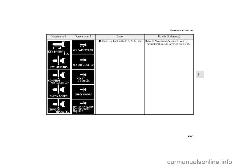
3-197
3
�There is a fault in the F. A. S. T. -key. Refer to “Free-hand Advanced Security
Transmitter (F.A.S.T.-key)” on page 3-16.
Screen type 1
Screen type 2
Cause
Do this (Reference)
BK0122500US.book 197 ページ 2010年5月12日 水曜日 午前11時11分
Page 313 of 714
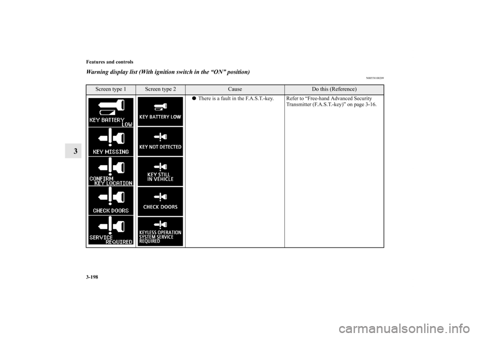
3-198 Features and controls
3
Warning display list (With ignition switch in the “ON” position)
N00558100209
Screen type 1
Screen type 2
Cause
Do this (Reference)
�There is a fault in the F.A.S.T.-key. Refer to “Free-hand Advanced Security
Transmitter (F.A.S.T.-key)” on page 3-16.
BK0122500US.book 198 ページ 2010年5月12日 水曜日 午前11時11分
![MITSUBISHI OUTLANDER 2011 2.G Owners Manual Features and controls
3-89
3 Steering wheel lock
N00512500166
[For vehicles equipped with the Free-hand Advanced Secu-
rity Transmitter (F.A.S.T.-key).]
For information on operations for vehicles equi](/manual-img/19/7521/w960_7521-203.png "MITSUBISHI OUTLANDER 2011 2.G Owners Manual Features and controls
3-89
3 Steering wheel lock
N00512500166
[For vehicles equipped with the Free-hand Advanced Secu-
rity Transmitter (F.A.S.T.-key).]
For information on operations for vehicles equi")