Page 343 of 514

5-24 Comfort controls
5
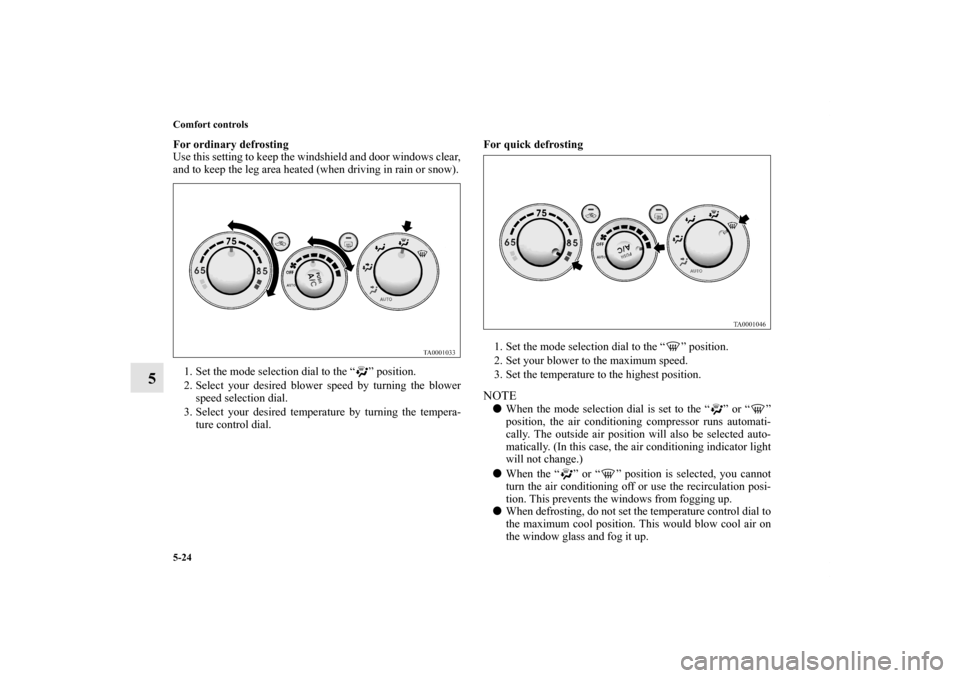
For ordinary defrosting
Use this setting to keep the windshield and door windows clear,
and to keep the leg area heated (when driving in rain or snow).
1. Set the mode selection dial to the “ ” position.
2. Select your desired blower speed by turning the blower
speed selection dial.
3. Select your desired temperature by turning the tempera-
ture control dial.For quick defrosting
1. Set the mode selection dial to the “ ” position.
2. Set your blower to the maximum speed.
3. Set the temperature to the highest position.
NOTE�When the mode selection dial is set to the “ ” or “ ”
position, the air conditioning compressor runs automati-
cally. The outside air position will also be selected auto-
matically. (In this case, the air conditioning indicator light
will not change.)
�When the “ ” or “ ” position is selected, you cannot
turn the air conditioning off or use the recirculation posi-
tion. This prevents the windows from fogging up.
�When defrosting, do not set the temperature control dial to
the maximum cool position. This would blow cool air on
the window glass and fog it up.
BK0121600US.book 24 ページ 2010年4月12日 月曜日 午前10時39分
Page 466 of 514
Vehicle care and maintenance
7-39
7
Passenger compartment fuse location tablePassenger compartment fuse location
No.
Symbol
Electrical system
Capacity
1
Rear air conditioning 5 A
2— — —
3Radio 30 A
4 Sunroof 20 A
5 Rear window defogger 30 A
6 Heater 30 A
7— — —
8 — — —
9 Power outlet 15 A
10 Power door locks 15 A
11 Rear window wiper 15 A
12 — — —
13 Engine control 7.5 A
14 Outside rearview mirrors 7.5 A
15 — — —
16 Cigarette lighter 15 A
17 Engine control 7.5 A
18 — — —
19 Door mirror heater 7.5 A
20 Relay 7.5 A
BK0121600US.book 39 ページ 2010年4月12日 月曜日 午前10時39分
Page 468 of 514

Vehicle care and maintenance
7-41
7
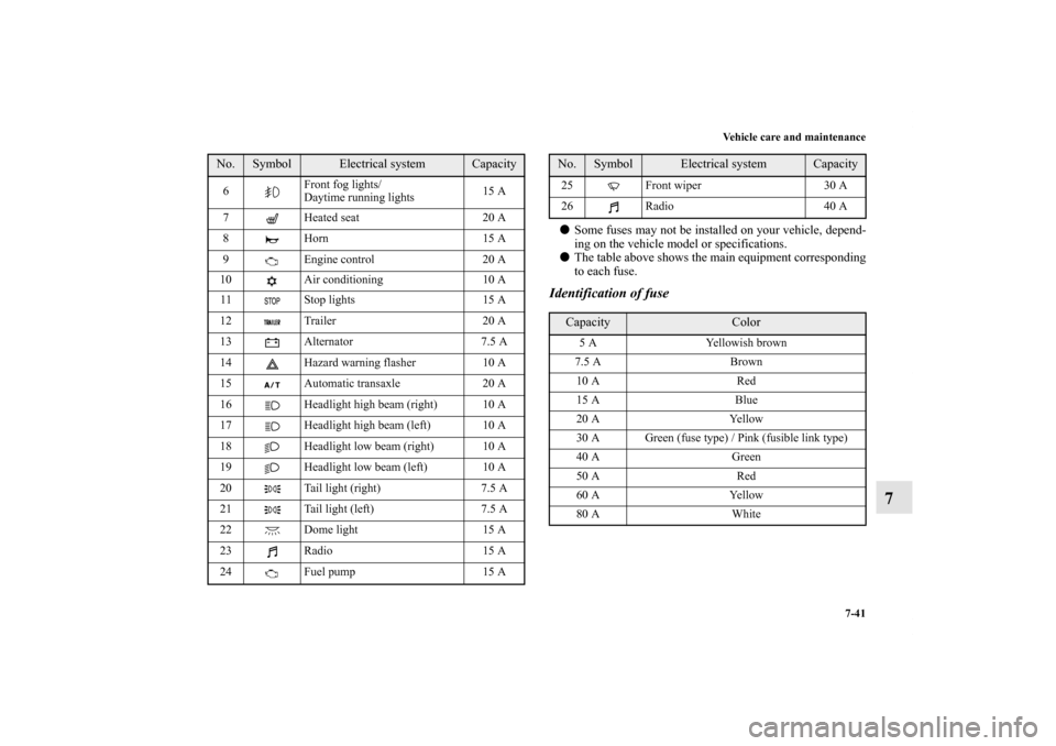
�Some fuses may not be installed on your vehicle, depend-
ing on the vehicle model or specifications.
�The table above shows the main equipment corresponding
to each fuse.Identification of fuse
6Front fog lights/
Daytime running lights15 A
7 Heated seat 20 A
8 Horn 15 A
9 Engine control 20 A
10 Air conditioning 10 A
11 Stop lights 15 A
12 Trailer 20 A
13 Alternator 7.5 A
14 Hazard warning flasher 10 A
15 Automatic transaxle 20 A
16 Headlight high beam (right) 10 A
17 Headlight high beam (left) 10 A
18 Headlight low beam (right) 10 A
19 Headlight low beam (left) 10 A
20 Tail light (right) 7.5 A
21 Tail light (left) 7.5 A
22 Dome light 15 A
23 Radio 15 A
24
Fuel pump 15 A No.
Symbol
Electrical system
Capacity
25 Front wiper 30 A
26 Radio 40 A Capacity
Color
5 A Yellowish brown
7.5 A Brown
10 A Red
15 A Blue
20 A Yellow
30 A Green (fuse type) / Pink (fusible link type)
40 A Green
50 A Red
60 A Yellow
80 A White
No.
Symbol
Electrical system
Capacity
BK0121600US.book 41 ページ 2010年4月12日 月曜日 午前10時39分
Page 471 of 514

7-44 Vehicle care and maintenance
7Replacement of light bulbs
N00942900219
Before replacing a bulb, be sure the light is off. Do not touch
the glass part of the new bulb with your bare fingers; the oil
from your skin will stay on the glass and dim or destroy the
bulb when it gets hot.NOTE�If you are unsure of how to carry out the work as required,
it is recommended that these procedures be carried out by
an authorized Mitsubishi Motors dealer or a repair facility
of your choice.
�Be careful not to scratch the vehicle body when removing
a light and lens.
�When it rains, or when the vehicle has been washed, the
inside of the lens sometimes becomes temporarily foggy.
This is the same phenomenon as when window glass mists
up on a humid day, and does not indicate a functional
problem.
When the light is switched on, the heat will remove the
fog. However, if water gathers inside the light, please
have it checked by an authorized Mitsubishi Motors
dealer or a repair facility of your choice.
Bulb capacity
N00943000099
The bulb should only be replaced with a new bulb with the
same rating and type. The type and rating are listed on the base
of the bulb.
CAUTION
!�Bulbs are extremely hot immediately after being
turned off.
When replacing a bulb, wait for it to cool sufficiently
before touching it. You could otherwise be burned.
BK0121600US.book 44 ページ 2010年4月12日 月曜日 午前10時39分
Page 472 of 514
Vehicle care and maintenance
7-45
7
Outside
N00950300788
NOTE�The high-mounted stop light uses LEDs rather than bulbs.
For repair and replacement, contact an authorized Mitsub-
ishi Motors dealer or a repair facility of your choice.
Description
Wattage or
Candle power
ANSI Trade No.
or Bulb type
1 - Headlight —9007
HB5
2 -Parking and front side-
marker and front turn
signal light24/2.2 cp 1157NA
3 -Front fog light
(if so equipped)55 W H11Front
Description
Wattage or
Candle power
ANSI Trade No.
or Bulb type
4 -Tail and stop and rear
side-marker light32/3 cp 1157
5 - Back-up light 21 cp 921
6 - Rear turn signal light 32 cp 1156NA
7 - License plate lights 5 W W5W
8 -High-mounted stop
lamp——Rear
BK0121600US.book 45 ページ 2010年4月12日 月曜日 午前10時39分
Page 476 of 514
Vehicle care and maintenance
7-49
7
Front fog lights
(if so equipped)
N00943600398
To r e m o v e1. Remove the six clips (A) by turning them counterclock-
wise or prying them, and remove the screw (B) by turning
it counterclockwise, then remove the cover (C).2. Depress the tab (D) on the harness connector and pull the
harness connector to downward to remove it.
BK0121600US.book 49 ページ 2010年4月12日 月曜日 午前10時39分
Page 477 of 514
7-50 Vehicle care and maintenance
7
3. Remove the bulb (E) by turning it counterclockwise.
CAUTION
!�Handle halogen light bulb with care. The gas inside
a halogen light bulb is highly pressurized, so drop-
ping, knocking, or scratching a halogen light bulb
can cause it to shatter.�Never hold the halogen light bulb with a bare hand,
dirty glove, etc. The oil from your hand could cause
the bulb to break the next time the fog lights are
used.
If the glass surface is dirty, clean it with alcohol and
let it dry completely before installing the bulb.
BK0121600US.book 50 ページ 2010年4月12日 月曜日 午前10時39分
Page 507 of 514

Alphabetical index
2Service brake 3-53
Warning light 3-83
Break-in recommendations 3-2
Bulb capacity 7-44
C
California Perchlorate Materials Requirements 1-9
Capacities 9-8
Cargo loads 4-12
Catalytic converter 7-3
Cautions on the handling of all-wheel drive vehicles 3-51
Certification label 9-4
Charging system warning light 3-85
Child restraints 2-25
Child safety locks for rear door 3-15
Cleaning
Inside of your vehicle 7-58
Outside of your vehicle 7-60
Clock 3-197
Coat hook 3-210
Combination headlights and dimmer switch 3-153
Consumer information 8-2
Coolant (engine) 7-9
,9-8
Cruise control 3-63
Indicator 3-64
Cup holder 3-206
D
Defogger (rear window) 3-163Digital clock 3-197
Dimensions 9-4
Dimmer (high/low beam change) 3-156
Disc brake pads 7-33
Dome light
Bulb capacity 7-46
Replacement 7-55
Switch 3-200
Door lights 3-202
Bulb capacity 7-46
Replacement 7-57
Doors
Locks 3-13
Power door locks 3-15
Warning light and buzzer 3-85
Drive belt 7-33
Driving during cold weather 4-5
Driving precaution 4-2
Driving, alcohol and drugs 4-3
E
Electric rear window defogger switch 3-163
Electronic immobilizer (Anti-theft starting system) 3-3
Emission-control system maintenance 7-31
Engine
Block heater 3-38
Compartment 7-6
Coolant 7-9
,9-8
Coolant temperature gauge 3-81
BK0121600US.book 2 ページ 2010年4月12日 月曜日 午前10時39分