Page 312 of 514

Driving safety
4-13
4
Loading cargo on the roof
N00630400054
WA R N I N G
!�Weight placed on the roof of the vehicle will raise the
vehicle’s center of gravity and adversely affect its
handling characteristics. As a result, driving errors
or emergency maneuvers could lead to a loss of con-
trol and result in an accident. Drive slowly and
avoid excessive maneuvers such as sudden braking
or quick turning.�Make sure that the weight of luggage and the roof
carrier do not exceed the maximum roof load {with-
out cross bars: 200 lb (91 kg), with cross bars: 150 lb
(68 kg)}. If the maximum roof load is exceeded, this
could cause damage to the vehicle or result in an
accident.�The total weight of all occupants and luggage,
including your roof load, must not exceed the vehicle
capacity weight. For more information, refer to
“Tire and loading information placard” on page 4-9.�Roof load is determined by adding the weight of the
roof carrier and the weight of the luggage placed on
the roof carrier.�For additional information, refer to “Maximum roof
load” on page 9-5.
CAUTION
!�Do not load luggage directly onto the roof. Use a roof
carrier that properly fits your vehicle.
For installation, refer to the instruction manual pro-
vided with the roof carrier.
BK0121600US.book 13 ページ 2010年4月12日 月曜日 午前10時39分
Page 315 of 514
, maximum tongue weight (B) and Gross Axle
Weight Rating (GAWR).Vehicle capacity weightThe vehicl")
4-16 Driving safety
4
Weight limitsNever exceed the vehicle capacity weight, maximum trailer
weight (A), maximum tongue weight (B) and Gross Axle
Weight Rating (GAWR).Vehicle capacity weightThe vehicle capacity weight is printed on the tire and loading
information placard as “combined weight of occupants and
cargo”.
This weight includes the weight of all occupants and the total
weight it can carry.
For detail information, refer to “Tire and loading information
placard” on page 4-9.
Maximum trailer weightRecommendations for towing up to this limit are as follows.Tongue weightThe tongue weight of any trailer is important because it affects
the vehicle capacity weight.
The vehicle capacity weight includes any cargo you may carry,
and the people who will be riding in the vehicle. If you tow a
trailer, you must include the tongue weight of the trailer in your
calculation of the vehicle capacity weight. Refer to “Tire and
loading information placard” on page 4-9, for more informa-
tion about vehicle capacity weight.
Do not exceed the tongue weight at 10 % of the loaded trailer
weight.
Example:
In case of your loaded weight is 3,500 lbs. (1,588 kg), the
tongue weight is 350 lbs. (160 kg).
Total Trailer WeightTrailer Brake and Towing kit*
requirements
Up to 1,500 lbs. (680 kg) Trailer brakes not required
1,500 lbs. (680 kg) to
2,000 lbs. (907 kg)Trailer brakes required
2,000 lbs. (907 kg) to
3,500 lbs. (1,588 kg)Trailer brakes and
Towing kit* required
*: Optional equipment
(including the large capacity radiator, full-size spare tire,
etc.)
BK0121600US.book 16 ページ 2010年4月12日 月曜日 午前10時39分
Page 450 of 514

Vehicle care and maintenance
7-23
7
Service Description
EXAMPLE: 95H
Maximum Load
Maximum load indicates the maximum load this tire is
designed to carry.
Maximum Pressure
Maximum Pressure indicates the maximum permissible
cold tire inflation pressure for this tire.Tire Identification Number (TIN)
The TIN may be found on one or both sides of the tire but
the date code may only be on one side. Look for the TIN
on the outboard side of tires as mounted on the vehicle. If
the TIN is not found on the outboard side then you will
find it on the inboard side of the tire.
EXAMPLE: DOT MA L9 ABCD 1504
95Load index
A numerical code associated with the maxi-
mum load a tire can carry.
HSpeed symbol
A symbol indicating the range of speeds at
which a tire can carry a load corresponding to
its load index under certain operating condi-
tions.
The maximum speed corresponding to the
speed symbol should only be achieved under
specified operating conditions. (i.e. tire pres-
sure, vehicle loading, road conditions and
posted speed limits)
WA R N I N G
!�Overloading of your tire is dangerous. Over-
loading can cause tire failure, affect vehicle
handling, and increase your stopping distance.
Use tires of the recommended load capacity for
your vehicle. Never overload them.
DOTDepartment of Transportation
This symbol certifies that the tire is in compli-
ance with the U.S. Department of Transporta-
tion tire safety standards, and is approved for
highway use.
MACode representing the tire manufacturing
location. (2 digits)
L9
ABCDCode representing the tire size. (2 digits)
Code used by tire manufacturer. (1 to 4 digits)
15Number representing the week in which the
tire was manufactured. (2 digits)
04Number representing the year in which the
tire was manufactured. (2 digits)
BK0121600US.book 23 ページ 2010年4月12日 月曜日 午前10時39分
Page 465 of 514
7-38 Vehicle care and maintenance
7
Ty p e B
1. Pull the lock lever.
2. Open the cover.Fuse load capacities This fuse list shows the names of the electrical systems and
their fuse capacities.
There are spare fuses in the cover of the instrument panel
(driver’s side). Always replace a blown fuse with one of the
same capacity as the original.
WA R N I N G
!�Do not touch the electronic control module (C). The
module surface can be too hot.
Wait for the electronic control module to cool down
before replacing a fuse.
BK0121600US.book 38 ページ 2010年4月12日 月曜日 午前10時39分
Page 466 of 514
Vehicle care and maintenance
7-39
7
Passenger compartment fuse location tablePassenger compartment fuse location
No.
Symbol
Electrical system
Capacity
1
Rear air conditioning 5 A
2— — —
3Radio 30 A
4 Sunroof 20 A
5 Rear window defogger 30 A
6 Heater 30 A
7— — —
8 — — —
9 Power outlet 15 A
10 Power door locks 15 A
11 Rear window wiper 15 A
12 — — —
13 Engine control 7.5 A
14 Outside rearview mirrors 7.5 A
15 — — —
16 Cigarette lighter 15 A
17 Engine control 7.5 A
18 — — —
19 Door mirror heater 7.5 A
20 Relay 7.5 A
BK0121600US.book 39 ページ 2010年4月12日 月曜日 午前10時39分
Page 467 of 514
7-40 Vehicle care and maintenance
7
�Some fuses may not be installed on your vehicle, depend-
ing on the vehicle model or specifications.
�The table above shows the main equipment corresponding
to each fuse.
The fuse block does not contain spare 7.5 A, 10 A and 15
A fuses. If a fuse of one of these capacities blows, replace
it temporarily by borrowing the one that matches from:
7.5 A: Door mirror heater
10 A: Headlight high beam (left)
15 A: Cigarette lighter
Replace the borrowed fuse as soon as possible.
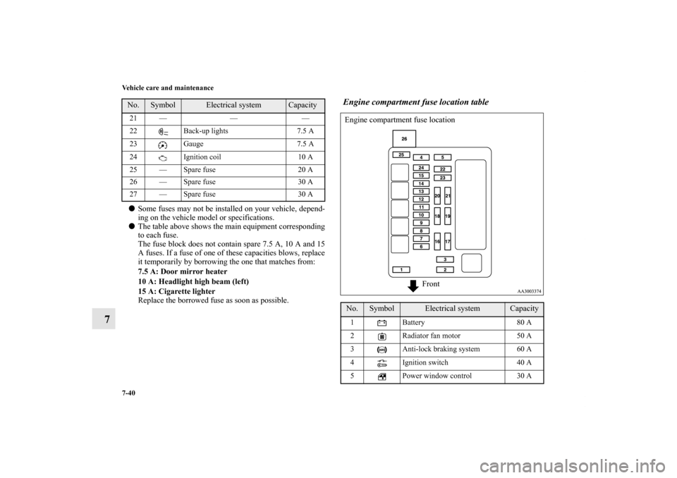
Engine compartment fuse location table
21 — — —
22 Back-up lights 7.5 A
23 Gauge 7.5 A
24 Ignition coil 10 A
25 — Spare fuse 20 A
26 — Spare fuse 30 A
27 — Spare fuse 30 A No.
Symbol
Electrical system
Capacity
No.
Symbol
Electrical system
Capacity
1 Battery 80 A
2 Radiator fan motor 50 A
3 Anti-lock braking system 60 A
4 Ignition switch 40 A
5 Power window control 30 A Engine compartment fuse location
Front
BK0121600US.book 40 ページ 2010年4月12日 月曜日 午前10時39分
Page 468 of 514

Vehicle care and maintenance
7-41
7
�Some fuses may not be installed on your vehicle, depend-
ing on the vehicle model or specifications.
�The table above shows the main equipment corresponding
to each fuse.Identification of fuse
6Front fog lights/
Daytime running lights15 A
7 Heated seat 20 A
8 Horn 15 A
9 Engine control 20 A
10 Air conditioning 10 A
11 Stop lights 15 A
12 Trailer 20 A
13 Alternator 7.5 A
14 Hazard warning flasher 10 A
15 Automatic transaxle 20 A
16 Headlight high beam (right) 10 A
17 Headlight high beam (left) 10 A
18 Headlight low beam (right) 10 A
19 Headlight low beam (left) 10 A
20 Tail light (right) 7.5 A
21 Tail light (left) 7.5 A
22 Dome light 15 A
23 Radio 15 A
24
Fuel pump 15 A No.
Symbol
Electrical system
Capacity
25 Front wiper 30 A
26 Radio 40 A Capacity
Color
5 A Yellowish brown
7.5 A Brown
10 A Red
15 A Blue
20 A Yellow
30 A Green (fuse type) / Pink (fusible link type)
40 A Green
50 A Red
60 A Yellow
80 A White
No.
Symbol
Electrical system
Capacity
BK0121600US.book 41 ページ 2010年4月12日 月曜日 午前10時39分
Page 470 of 514
Vehicle care and maintenance
7-43
7
5. Use the fuse location diagrams and the matching tables, to
check the fuse that is related to the problem. If the fuse is
not blown, something else must be causing the problem.
Contact an authorized Mitsubishi Motors dealer or a
repair facility of your choice to have the problem checked.6. Insert a new fuse of the same capacity securely into the
appropriate slot. A- Fuse is OK
B- Blown fuse
CAUTION
!�Never use a fuse with a capacity greater than the one
listed or any substitute, such as wire, foil etc. This
would cause the circuit wiring to heat up and could
cause a fire. �If the replacement fuse blows again after a short
time, have the electrical system checked by an
authorized Mitsubishi Motors dealer or a repair
facility of your choice to find and correct the cause.
BK0121600US.book 43 ページ 2010年4月12日 月曜日 午前10時39分