2011 MINI Clubman inflation pressure
[x] Cancel search: inflation pressurePage 193 of 256

Wheels and tiresMOBILITY
191
Tire inflation pressures for driving above
100 mph or 160 km/h
In order to drive at maximum speeds in
excess of 100mph or 160km/h, adjust
pressures to the respective tire inflation pres-
sures listed on the foll owing pages in the col- umns for traveling speeds including those
exceeding 100 mph or 160 km/h. Otherwise,
tire damage and accidents could occur.<
Observe all national and local maximum speed
limits; otherwise, violations of the law could
occur.
MINI Cooper Clubman tire inflation pressures
Tire size Pressure specifications in psi/kPa
Speeds up to a max. of
100 mph /160 km/h Speeds including those
exceeding
100 mph / 160 km/h
All pressure specifications in the
table are indicated in psi/kilopas-
cal with cold tires. Cold = ambient
temperature
195/55 R 16 87 H
195/55 R 16 87 H RSC
195/55 R 16 87 H M+S RSC
195/55 R 16 87 V M+S RSC 32/220 32/220 35/240 38/260
175/65 R 15 84 T M+S
175/65 R 15 84 H M+S
175/65 R 15 84 H
175/60 R 16 82 H M+S RSC
205/45 R 17 84 V RSC
205/45 R 17 84 V M+S RSC
205/40 R 18 82 W RSC 35/240 35/240 38/260 41/280
Space-saver spare tire:
115/70 R 15 90 M Speeds up to a max. of 50 mph/80 km/h
60/420
More details on the perm issible load and weights can be found on page 228.
Page 194 of 256

MOBILITYWheels and tires
192
MINI Cooper S Clubman tire inflation pressures
Tire size Pressure specifications in psi/kPa
Speeds up to a max. of
100 mph /160 km/h Speeds including those
exceeding
100 mph / 160 km/h
All pressure specifications in the
table are indicated in psi/kilopas-
cal with cold tires. Cold = ambient
temperature
195/55 R 16 87 V RSC
195/55 R 16 87 H M+S RSC
195/55 R 16 87 V M+S RSC 35/240 35/240 38/260 41/280
205/45 R 17 84 V RSC
205/45 R 17 84 V M+S RSC
205/40 R 18 82 W RSC
175/60 R 16 82 H M+S RSC 38/260 38/260 41/280 44/300
More details on the permissible load and weights can be found on page228.
Page 195 of 256

Wheels and tiresMOBILITY
193
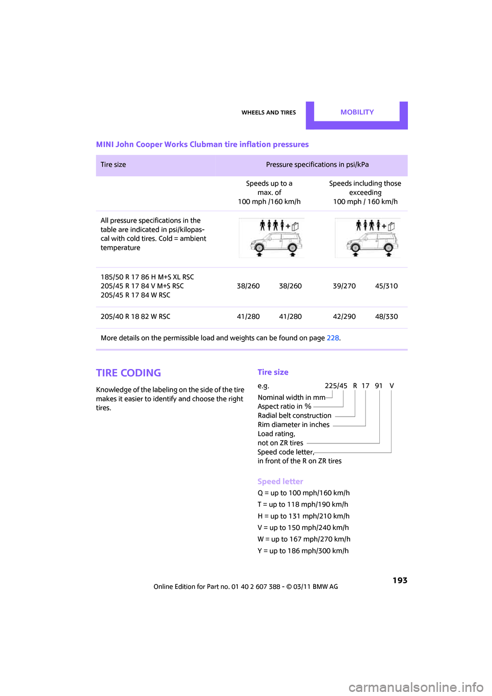
MINI John Cooper Works Clubman tire inflation pressures
Tire coding
Knowledge of the labeling on the side of the tire
makes it easier to identify and choose the right
tires.
Tire size
Speed letter
Q = up to 100 mph/160 km/h
T = up to 118 mph/190 km/h
H = up to 131 mph/210 km/h
V = up to 150 mph/240 km/h
W = up to 167 mph/270 km/h
Y = up to 186 mph/300 km/h
Tire size Pressure specifications in psi/kPa
Speeds up to a max. of
100 mph /160 km/h Speeds including those
exceeding
100 mph / 160 km/h
All pressure specifications in the
table are indicated in psi/kilopas-
cal with cold tires. Cold = ambient
temperature
185/50 R 17 86 H M+S XL RSC
205/45 R 17 84 V M+S RSC
205/45 R 17 84 W RSC 38/260 38/260 39/270 45/310
205/40 R 18 82 W RSC 41/280 41/280 42/290 48/330
More details on the perm issible load and weights can be found on page 228.
e.g.
Nominal width in mm
Aspect ratio in Ξ
Radial belt construction
Rim diameter in inches
Load rating,
not on ZR tires
Speed code letter,
in front of the R on ZR tires225/45 R 17 91 V
Page 199 of 256

Wheels and tiresMOBILITY
197
marked with a clearly visible MINI designation
on the sidewall of the tire.
When properly used, these tires meet the high-
est standards in terms of safety and handling
characteristics.
Run-flat tires*
When mounting new tires or changing over from
summer to winter tires and vice versa, mount
run-flat tires for your own safety. Keep in mind
that no space-saver spare tire is available in the
event of a flat. Your MINI dealer will be glad to
advise you.
Special characteristics of winter tires
The manufacturer of MINI recommends the use
of winter tires on roads during the winter, or if
temperatures drop below 45 7/ +7 6.
Although all-season M+S tires provide better
winter traction than summer tires, they gener-
ally fail to provide the same levels of cold-
weather performance as winter tires.
Pay attention to speed
Always comply with the speed limit for the
winter tires mounted on your car; failure
to do so could result in tire damage and acci-
dents. <
If the car is capable of speeds higher than that
permitted for the winter ti res, a label stating the
maximum permitted speed for the mounted
tires must be displayed in your field of view. This
label is available at your tire dealer or MINI
dealer.
Storage
Always store wheels and tires in a cool, dry place
with as little exposure to light as possible.
Always protect tires agains t all contact with oil,
grease and fuels.
Do not exceed the maximum tire inflation pres-
sure indicated on the sidewall of the tire.
Swapping wheels among the axles
Depending on the individual use, front and rear
tires may exhibit diff erent wear and tear.
In order to maintain an even wear and tear, the
wheels may be rotated between the axles. Your
MINI dealer will be glad to advise you.
Always check the inflation pressure after the tire
rotation, if necessary change the pressure.
Snow chains*
Only certain types of fi ne-link snow chains have
been tested by the manufacturer of your MINI,
classified as road-saf e and recommended. Con-
tact your MINI deal er for more details.
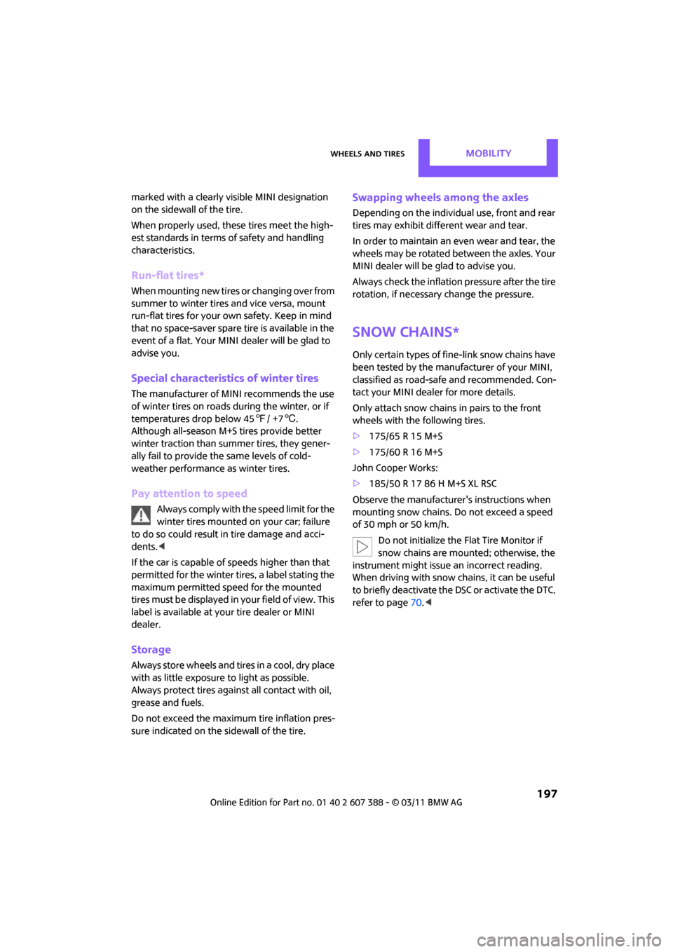
Only attach snow chains in pairs to the front
wheels with the following tires.
> 175/65 R 15 M+S
> 175/60 R 16 M+S
John Cooper Works:
> 185/50 R 17 86 H M+S XL RSC
Observe the manufacturer's instructions when
mounting snow chains. Do not exceed a speed
of 30 mph or 50 km/h. Do not initialize the Flat Tire Monitor if
snow chains are mounted; otherwise, the
instrument might issue an incorrect reading.
When driving with snow chains, it can be useful
to briefly deactivate the DSC or activate the DTC,
refer to page 70.<
Page 216 of 256

MOBILITYReplacing components
214
3Holder for the sealant bottle
4 Compressor
5 Plug and cable for the socket in the vehicle
interior, page 94
6 Connection hose to connect the compressor
and sealant bottle or the compressor and
wheel
7 On/off switch
8 Pressure gauge for indi cating the tire infla-
tion pressure
9 Release button for reduci ng the tire inflation
pressure
Connector, cable and connection hose are
stored in the compressor housing.
Using the Mobility System
To repair a tire puncture with the Mobility Sys-
tem, proceed as follows:
> Filling the tire with sealant
> Distributing the sealant
> Correct the tire inflation pressure
Filling the tire with sealant
Proceed in the specified order; otherwise,
sealant may emerge under high pres-
sure. <
1. Shake the sealant bottle.
2. Pull the connecting hose 6 completely out of
the compressor housing and screw it onto
the connector of the sealant bottle. Make
sure that the hose is not kinked.
3. Insert the sealant bo ttle on the compressor
housing in an upright position. 4.
Unscrew the dust cap from the valve of the
defective wheel and screw the filling hose 2
of the sealant bottle onto the valve.
5. Ensure that the compre ssor is switched off.
6. Insert the plug 5 into the lighter socket/
power socket in the vehicle interior,
page 94.
7. With the engine running:
Switch on the compressor and let is run for
approx. 3 to 8 minutes to fill the tire with
sealant and achieve a ti re inflation pressure
of approx. 26 psi/180 kPa.
When filling the tire with sealant, the
inflation pressure can briefly rise to
approx. 73 psi/500 kPa. Do not switch off
the compressor during this phase. <
Do not run the compressor for longer
than 10 minutes; otherwise, the
device will overheat and possibly be dam-
aged.<
8. Switch off the compressor.
If an air pressure of 26 psi/180 kPa is not
reached:
1. Unscrew the filling hose 2 from the wheel
and drive the vehicle forward and backward
approx. 33 ft/10 m to distribute the liquid
sealant in the tire evenly.
2. Inflate the tire again with the compressor.
If an inflation pressure of 26 psi/180 kPa
still cannot be reached, the tire is too
heavily damaged. Please contact the nearest
MINI dealer. <
Page 217 of 256

Replacing componentsMOBILITY
215
Stowing Mobility System
1.Unscrew filler hose 2 of the sealant bottle
from the wheel.
2. Unscrew connecting hose of the
compressor 6 from the sealant bottle.
3. Connect the filler hose 2 of the sealant bot-
tle to the unoccupied connection on the
sealant bottle.
This prevents the rest of the sealant from
escaping from the bottle.
4. Wrap the empty sealant bottle in suitable
material to avoid dirtying the cargo area.
5. Stow Mobility System back in the vehicle.
Distributing the sealant
Immediate drive approx. 3.1 miles/5 km so that
the sealant evenly distributes itself.
Do not exceed speeds of 50 mph/
80 km/h.
If possible, do not drop below 10 mph/
20 km/h.<
Adjusting the tire pressure
1. After driving approx. 3.1 miles/5 km or
10 minutes, stop at a suitable location.
2. Screw the connection hose 6 of the com-
pressor directly onto the tire valve.
3. Insert the plug 5 into the power socket in
the vehicle interior.
4. Correct inflation pressu re to 26 psi/180 kPa.
With the engine running:
> To increase the inflatio n pressure: switch on
the compressor. To check the current infla-
tion pressure, switch off the compressor.
Do not run the compressor for longer
than 10 minutes; otherwise, the
device will overheat and possibly be dam-
aged. <
> To decrease the inflation pressure: press the
release button 9. If the tire cannot ma
intain the inflation
pressure, drive the vehicle again, refer to
Distributing the sealan t. Then repeat steps
1to4.
If an inflation pressure of 26 psi/180 kPa still
cannot be reached, the tire is too heavily dam-
aged. Contact the nearest MINI dealer. <
Driving on
Do not exceed the permitted maximum
speed of 50 mph/80 km/h; doing so may
result in an accident.<
Replace the defective tire as soon as possible
and have the new wheel/tire assembly bal-
anced.
Have the Mobility System refilled.
Changing wheels
Run-flat tires*
Tire change for run-flat tires:
> Prepare for tire change, page 216
> Jack up vehicle, page 216
> Tighten lug bolts, page 217
Space-saver spare tire*
Tire change with space-saver spare tire:
>Remove the space-saver spare tire,
page 215
> Prepare for tire change, page 216
> Jack up vehicle, page 216
> Mount space-saver spare tire, page 217
> Tighten lug bolts, page 217
> Drive with space-saver spare tire, page 216
Removing the space-saver spare tire
The space-saver spare tire is located under the
tire change set in the cargo area.
Page 218 of 256

MOBILITYReplacing components
216
1.Fold up the floor mat.
2. Unscrew the nut, arrow, and remove the
space-saver spare tire.
Driving with the space-saver spare tire
Drive cautiously and do not exceed a
speed of 50 mph/80 km/h. Changes may
occur in vehicle handling such as lower track sta-
bility during br aking, longer braking distances
and changes in self-steering properties when
close to the handling limit. These properties are
more noticeable with winter tires. <
Only one space-saver spare tire may be
mounted at one time. Mount a wheel and
tire of the original size as soon as possible, to
avoid any safety risks. <
Check the tire inflation pressure at the ear-
liest opportunity and correct it if neces-
sary. Replace the defective tire as soon as possi-
ble and have the new wheel/tire assembly
balanced. <
Preparing for a tire change
Observe the safety precautions regarding
flat tires on page 213.<
Additional safety measures when chang-
ing tires:
Only change the tire wh en parked on a surface
that is level, firm and not slippery.
The vehicle or the jack could slip sideways on
soft or slippery support surfaces, such as snow,
ice, flagstones, etc.
Do not use a wooden block or similar object as a
support base for the jack, as this would prevent
it from extending to its full support height and
reduce its load-carrying capacity. Do not lie under the vehicle or start the engine
when the vehicle is supported by the jack; other-
wise, there is a risk of fatal injury.
<
1. Place the foldable chock
* behind the front
wheel on the other side of the vehicle or in
front of the wheel if the vehicle is on an
incline. If the wheel is changed on a surface
with a more severe sl ope, take additional
precautions to secure the vehicle from roll-
ing.
2. Uncover the lug bolts if necessary.
3. Loosen the lug bolts by a half turn.
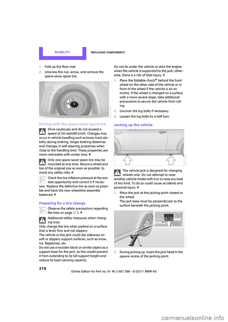
Jacking up the vehicle
The vehicle jack is designed for changing
wheels only. Do not attempt to raise
another vehicle model with it or to raise any load
of any kind. To do so could cause accidents and
personal injury. <
1. Place the jack at the jacking point closest to
the wheel.
The jack base must be perpendicular to the
surface beneath the jacking point.
2. During jacking up, insert the jack head in the
square recess of the jacking point.
Page 240 of 256

238
REFERENCEEverything from A to Z
Everything from A to Z
INDEX
A
ABS Antilock Brake System69
Accessories, refer to Your individual vehicle 4
Acknowledgment signals for
locking/unlocking vehicle 28
Activated-charcoa l filter for
automatic climate control 89
Adaptive Light Control 82
Additives
– coolant 200
– engine oil 200
Address, entering 115
Address for navigation
– entering 109,115
Adjusting temperature inside the car, refer to Air
conditioner 86
Adjusting temperature inside
the car, refer to Automatic
climate control 87
Adjusting the tone during
audio operation, refer to
Tone control 131
Air conditioner 85
Air conditioning mode
– air conditioner 86
– automatic cl imate control87
– ventilation 89
Air distribution
– automatic 88
– individual 87
– manual 87
Air flow rate 86,88
– air conditioning system 86
– automatic cl imate control88
– heating, ventilation 86
Air outlets, refer to Air vents 85Air pressure, checking, refer to
Tire inflation pressure 190
Air recirculation, refer to
Recirculated-air
mode 86,88
Air supply
– air conditioner 86
– automatic climate control 87
– ventilation 89
Air vents 85
Airbags 78
– sitting safely 37
– warning lamp 80
Airing, refer to Ventilation89
AKI, refer to Fuel grade 189
Alarm system 31
All-season tires, refer to Winter tires 197
AM, waveband 132
Am
bient air, refer to
Recirculated-air
mode 86,88
Ambient lighting 84
Antenna, care 204
Antifreeze
– coolant 200
– washer fluid 53
Antilock Brake System ABS 69
Anti-theft alarm system, refer
to Alarm system 31
Anti-theft system 27
Approved axle loads, refer to
Weights 228
Approved engine oils 200
Approved gross vehicle
weight, refer to Weights 228
Armrest, refer to Center armrest 93
Arrival time
– computer 58
– route guidance 118Ashtray
94
Assistant systems, refer to
– Dynamic Stability Control
DSC 69
Audio 130
– controls 130
– switching on/off 130
– tone control 131
– volume 130
Audio device, external 93
AUTO program for automatic climate control 88
Automatic
– air distribution 88
– air flow rate 88
– cruise control 54
– headlamp control 81
Automatic climate control 85
– automatic air distribution 88
Automatic transmission with
Steptronic 48
– interlock 49
– overriding selector lever
lock 50
– shiftlock 49
– sport program 50
Auxiliary phone 166
AUX-IN connection 142
AUX-IN, refer to External audio
device 93
Average fuel consumption 57
– setting the units 60
Average speed 57
Avoiding highways for navigation 118
Axle loads, refer to Weights 228