2011 MERCEDES-BENZ SLS trailer
[x] Cancel search: trailerPage 296 of 436
Parktronic system
The Parktronic system is an electronic
parking aid with ultrasonic sensors designed
to assist the driver during parking maneuvers.
The Parktronic system indicates the relative
distance between the vehicle and an obstacle
visually and audibly.
The Parktronic system is activated
automatically when
Ryou switch on the ignition
and
Ryou release the electronic parking brake
or
Ryou start the engine
and
Rshift the transmission into drive position
D, reverse gear R, or neutral position N
The Parktronic system deactivates at speeds
above approximately 11 mph (18 km/h). At
lower speeds, the Parktronic system
activates again.
The Parktronic system also deactivates when
you shift the transmission into park position
P or engage the electronic parking brake and
turn off the engine.
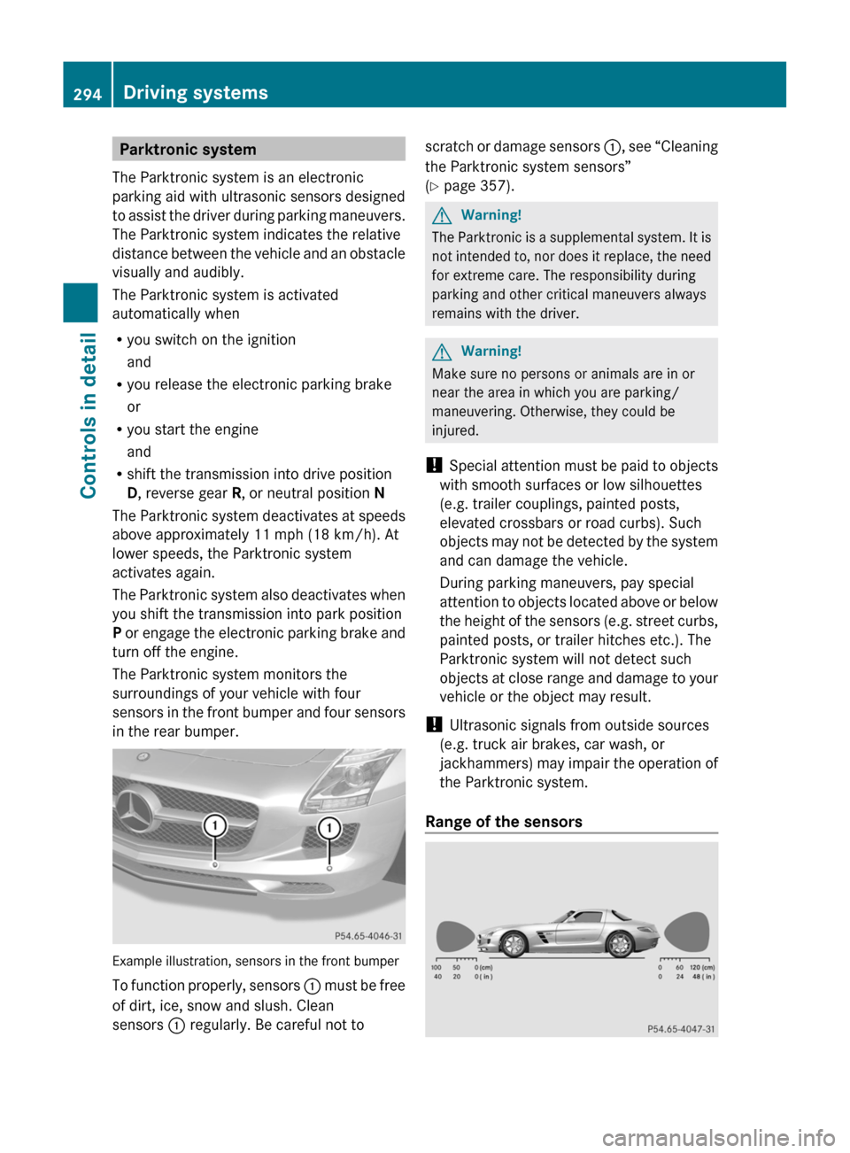
The Parktronic system monitors the
surroundings of your vehicle with four
sensors in the front bumper and four sensors
in the rear bumper.
Example illustration, sensors in the front bumper
To function properly, sensors : must be free
of dirt, ice, snow and slush. Clean
sensors : regularly. Be careful not to
scratch or damage sensors :, see “Cleaning
the Parktronic system sensors”
(Y page 357).
GWarning!
The Parktronic is a supplemental system. It is
not intended to, nor does it replace, the need
for extreme care. The responsibility during
parking and other critical maneuvers always
remains with the driver.
GWarning!
Make sure no persons or animals are in or
near the area in which you are parking/
maneuvering. Otherwise, they could be
injured.
! Special attention must be paid to objects
with smooth surfaces or low silhouettes
(e.g. trailer couplings, painted posts,
elevated crossbars or road curbs). Such
objects may not be detected by the system
and can damage the vehicle.
During parking maneuvers, pay special
attention to objects located above or below
the height of the sensors (e.g. street curbs,
painted posts, or trailer hitches etc.). The
Parktronic system will not detect such
objects at close range and damage to your
vehicle or the object may result.
! Ultrasonic signals from outside sources
(e.g. truck air brakes, car wash, or
jackhammers) may impair the operation of
the Parktronic system.
Range of the sensors
294Driving systemsControls in detail
BA 197 USA, CA Edition A 2011; 1; 27, en-UShereepeVersion: 3.0.3.52010-03-24T15:31:10+01:00 - Seite 294
Page 337 of 436
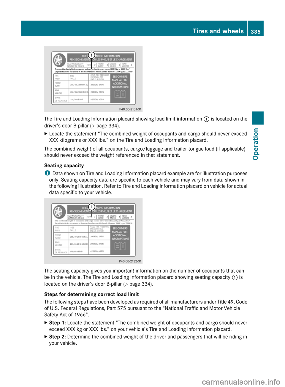
The Tire and Loading Information placard showing load limit information : is located on the
driver’s door B-pillar ( Y page 334).
XLocate the statement “The combined weight of occupants and cargo should never exceed
XXX kilograms or XXX lbs.” on the Tire and Loading Information placard.
The combined weight of all occupants, cargo/luggage and trailer tongue load (if applicable)
should never exceed the weight referenced in that statement.
Seating capacity
i Data shown on Tire and Loading Information placard example are for illustration purposes
only. Seating capacity data are specific to each vehicle and may vary from data shown in
the following illustration. Refer to Tire and Loading Information placard on vehicle for actual
data specific to your vehicle.
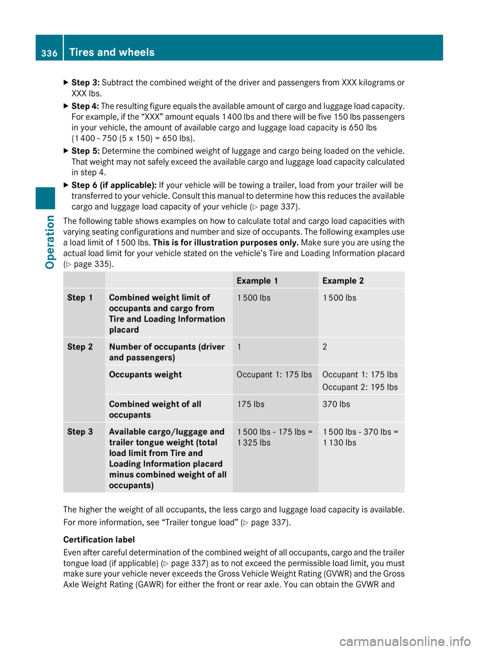
The seating capacity gives you important information on the number of occupants that can
be in the vehicle. The Tire and Loading Information placard showing seating capacity : is
located on the driver’s door B-pillar ( Y page 334).
Steps for determining correct load limit
The following steps have been developed as required of all manufacturers under Title 49, Code
of U.S. Federal Regulations, Part 575 pursuant to the “National Traffic and Motor Vehicle
Safety Act of 1966”.
XStep 1: Locate the statement “The combined weight of occupants and cargo should never
exceed XXX kg or XXX lbs.” on your vehicle’s Tire and Loading Information placard.XStep 2: Determine the combined weight of the driver and passengers that will be riding in
your vehicle.Tires and wheels335OperationBA 197 USA, CA Edition A 2011; 1; 27, en-UShereepeVersion: 3.0.3.52010-03-24T15:31:10+01:00 - Seite 335Z
Page 338 of 436
XStep 3: Subtract the combined weight of the driver and passengers from XXX kilograms or
XXX lbs.XStep 4: The resulting figure equals the available amount of cargo and luggage load capacity.
For example, if the “XXX” amount equals 1 400 lbs and there will be five 150 lbs passengers
in your vehicle, the amount of available cargo and luggage load capacity is 650 lbs
(1 400 - 750 (5 x 150) = 650 lbs).XStep 5: Determine the combined weight of luggage and cargo being loaded on the vehicle.
That weight may not safely exceed the available cargo and luggage load capacity calculated
in step 4.XStep 6 (if applicable): If your vehicle will be towing a trailer, load from your trailer will be
transferred to your vehicle. Consult this manual to determine how this reduces the available
cargo and luggage load capacity of your vehicle ( Y page 337).
The following table shows examples on how to calculate total and cargo load capacities with
varying seating configurations and number and size of occupants. The following examples use
a load limit of 1 500 lbs. This is for illustration purposes only. Make sure you are using the
actual load limit for your vehicle stated on the vehicle’s Tire and Loading Information placard
( Y page 335).
Example 1Example 2Step 1Combined weight limit of
occupants and cargo from
Tire and Loading Information
placard1 500 lbs1 500 lbsStep 2Number of occupants (driver
and passengers)12Occupants weightOccupant 1: 175 lbsOccupant 1: 175 lbs
Occupant 2: 195 lbsCombined weight of all
occupants175 lbs370 lbsStep 3Available cargo/luggage and
trailer tongue weight (total
load limit from Tire and
Loading Information placard
minus combined weight of all
occupants)1 500 lbs - 175 lbs =
1 325 lbs1 500 lbs - 370 lbs =
1 130 lbs
The higher the weight of all occupants, the less cargo and luggage load capacity is available.
For more information, see “Trailer tongue load” ( Y page 337).
Certification label
Even after careful determination of the combined weight of all occupants, cargo and the trailer
tongue load (if applicable) (Y page 337) as to not exceed the permissible load limit, you must
make sure your vehicle never exceeds the Gross Vehicle Weight Rating (GVWR) and the Gross
Axle Weight Rating (GAWR) for either the front or rear axle. You can obtain the GVWR and
336Tires and wheelsOperation
BA 197 USA, CA Edition A 2011; 1; 27, en-UShereepeVersion: 3.0.3.52010-03-24T15:31:10+01:00 - Seite 336
Page 339 of 436
GAWR from the certification label. The certification label can be found on the driver’s door
B-pillar, see the “Technical data” section ( Y page 421).
Gross Vehicle Weight Rating (GVWR): The total weight of the vehicle, all occupants, all cargo,
and the trailer tongue load (if applicable) must never exceed the GVWR.
Gross Axle Weight Rating (GAWR): The total allowable weight that can be carried by a single
axle (front or rear).
To assure that your vehicle does not exceed the maximum permissible weight limits (GVWR
and GAWR for front and rear axle), have the loaded vehicle (including driver, passengers and
all cargo and, if applicable, trailer fully loaded) weighed on a suitable commercial scale.
Trailer tongue load
The tongue load of any trailer is an important weight to measure because it affects the load
you can carry in your vehicle. If a trailer is towed, the tongue load must be added to the weight
of all occupants riding and any cargo you are carrying in the vehicle. The tongue load typically
is 10% of the trailer weight and everything loaded in it.
Your Mercedes-Benz has been designed primarily to carry passengers and their cargo.
Mercedes-Benz does not recommend trailer towing with your vehicle.Maximum tire loadGWarning!
Do not overload the tires by exceeding the
specified load limit as indicated on the Tire
and Loading Information placard on the
driver’s door B-pillar. Overloading the tires
can overheat them, possibly causing a
blowout. Overloading the tires can also result
in handling or steering problems, or brake
failure.
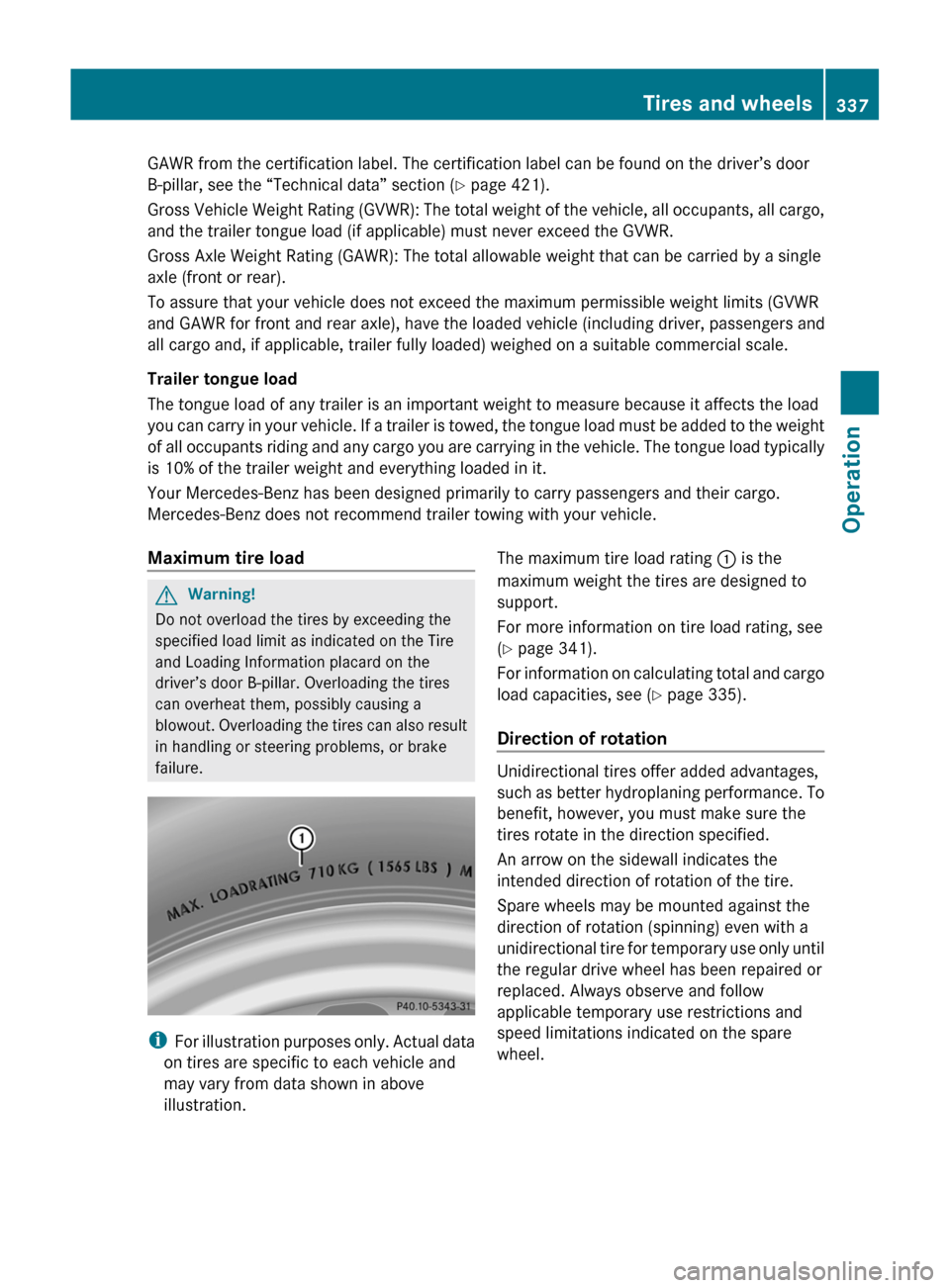
i For illustration purposes only. Actual data
on tires are specific to each vehicle and
may vary from data shown in above
illustration.
The maximum tire load rating : is the
maximum weight the tires are designed to
support.
For more information on tire load rating, see
( Y page 341).
For information on calculating total and cargo
load capacities, see ( Y page 335).
Direction of rotation
Unidirectional tires offer added advantages,
such as better hydroplaning performance. To
benefit, however, you must make sure the
tires rotate in the direction specified.
An arrow on the sidewall indicates the
intended direction of rotation of the tire.
Spare wheels may be mounted against the
direction of rotation (spinning) even with a
unidirectional tire for temporary use only until
the regular drive wheel has been repaired or
replaced. Always observe and follow
applicable temporary use restrictions and
speed limitations indicated on the spare
wheel.
Tires and wheels337OperationBA 197 USA, CA Edition A 2011; 1; 27, en-UShereepeVersion: 3.0.3.52010-03-24T15:31:10+01:00 - Seite 337Z
Page 347 of 436
may vary from data shown in above
illustration.
This marking tells you about the type of cord
and number of plies in the sidewall : and
under the tread ;.
Tire and loading terminology
Accessory weight
The combined weight (in excess of those
standard items which may be replaced) of
transmission, power steering, power brakes,
power windows, power seats, radio, and
heater, to the extent that these items are
available as factory-installed equipment
(whether installed or not).
Air pressure
The amount of air inside the tire pressing
outward on each square inch of the tire. Air
pressure is expressed in pounds per square
inch (psi), kilopascal (kPa), or bar.
Aspect ratio
Dimensional relationship between tire
section height and section width expressed
in percentage.
Bar
Metric unit for air pressure. There are
14.5038 pounds per square inch (psi) to
1 bar; there are 100 kilopascals (kPa) to 1 bar.
Bead
The tire bead contains steel wires wrapped by
steel cords that hold the tire onto the rim.
Cold tire inflation pressure
Tire inflation pressure when your vehicle has
been sitting for at least 3 hours or driven no
more than 1 mile (1.6 km).
Curb weight
The weight of a motor vehicle with standard
equipment including the maximum capacity
of fuel, oil, and coolant, and, if so equipped,
air conditioning and additional optional
equipment, but without passengers and
cargo.
DOT (Department of Transportation)
A tire branding symbol which denotes the tire
meets requirements of the U.S. Department
of Transportation.
GAWR (Gross Axle Weight Rating)
The GAWR is the maximum permissible axle
weight. The gross vehicle weight on each axle
must never exceed the GAWR for the front
and rear axle indicated on the certification
label located on the driver’s door B-pillar.
GVW (Gross Vehicle Weight)
The GVW comprises the weight of the vehicle
including fuel, tools, spare wheel, installed
accessories, passengers and cargo and, if
applicable, trailer tongue load. The GVW must
never exceed the GVWR indicated on the
certification label located on the driver’s door
B-pillar.
GVWR (Gross Vehicle Weight Rating)
This is the maximum permissible vehicle
weight of the fully loaded vehicle (weight of
the vehicle including all options, passengers,
fuel, and cargo and, if applicable, trailer
tongue load). It is indicated on the
certification label located on the driver’s door
B-pillar.
Kilopascal (kPa)
Metric unit for air pressure. There are 6.9 kPa
to 1 psi; another metric unit for air pressure
is bar. There are 100 kilopascals (kPa) to
1 bar.
Load index
Numerical code associated with the
maximum load a tire can support.
Maximum load rating
The maximum load in kilograms and pounds
that can be carried by the tire.Tires and wheels345OperationBA 197 USA, CA Edition A 2011; 1; 27, en-UShereepeVersion: 3.0.3.52010-03-24T15:31:10+01:00 - Seite 345Z