2011 MERCEDES-BENZ S-Class stowage
[x] Cancel search: stowagePage 437 of 524

pressed the SOS button. Carefully leave the
vehicle and move to a safe location. The
Response Center will automatically contact
local emergency officials with the vehicle's
approximate location if they receive an
automatic SOS signal and cannot make voice
contact with the vehicle occupants.
Roadside Assistance call buttonXOpen the stowage compartment under the
armrest ( Y page 423).XPress and hold Roadside Assistance
button : for more than two seconds.
A call to a Mercedes-Benz Roadside
Assistance Representative is initiated. The
indicator lamp in Roadside Assistance
button : flashes while the call is active.
The Connecting Call message appears in
the COMAND display and COMAND is
muted.
If a connection can be established, the Call
Connected message appears in the
COMAND display.
If a mobile phone network is available and
there is sufficient GPS reception, the mbrace
system transmits data to the Response
Center, for example:
R current location of the vehicle
R vehicle identification number
R vehicle model
R vehicle color
i The COMAND display shows that an
mbrace call is active. You can switch to the
navigation menu by pressing the
S button on COMAND during the call.
Spoken commands are not available.
A voice connection is established between
the Mercedes-Benz Roadside Assistance
Representative and the vehicle occupants.XDescribe the type of assistance needed.
The Mercedes-Benz Roadside Assistance
Representative either sends a qualified
Mercedes-Benz technician or organizes for
your vehicle to be transported to the nearest
authorized Mercedes-Benz Center. You may
be charged for services such as repair work
and/or towing. Further details are available
in your mbrace manual.
i If the indicator lamp in MB info call
button : flashes continuously and it was
not possible to establish a voice
connection to the Response Center, then
the mbrace system has failed to initiate a
Roadside Assistance call (e.g. the
corresponding cellular phone network is
not available). The Call Failed message
appears in the multifunction display.
The COMAND display shows the Call
could not be connected! message.
Press W to confirm the message.
XTo end a call: press the ~ button on the
multifunction steering wheel.
or
XPress the corresponding button for ending
a phone call on the COMAND telephone
keypad.
i Sign and Drive services 30
: you are not
charged for services such as jump-starting,
providing a few gallons of fuel for a fuel tank
that has been run dry or changing a flat tire
with the vehicle's own spare tire.
30 USA only.Features435Loading, stowing and featuresZ
Page 438 of 524

MB Info call buttonXThe stowage compartment under the
armrest ( Y page 423).XPress and hold MB info call button : for
more than two seconds.
A call to the Response Center is initiated.
MB info call button indicator lamp :
flashes while the connection is being
established. The Connecting Call
message appears in the multifunction
display. The COMAND display shows the
Information Call Activated message.
The audio system or COMAND is muted.
If a connection can be established, the Call
Connected message appears in the
multifunction display.
The COMAND display shows the
Information Call Activated message.
If a mobile phone network is available and
there is sufficient GPS reception, the mbrace
system transmits data to the Response
Center, for example:
R current location of the vehicle
R vehicle identification number
R vehicle model
R vehicle color
i The COMAND display shows that an
mbrace call is active. You can switch to the
navigation menu by pressing the S
button on COMAND during the call. Spoken
commands are not available.
A voice connection between the Response
Center and the vehicle occupants is
established. You can obtain information on
how to operate your vehicle's systems, on the
location of the nearest authorized Mercedes-
Benz Center, and on further products and
services offered by Mercedes-Benz USA.
Further details on the mbrace system can be
found under http://www.mbusa.com 31
.
Log in under "Owners Online".
i If the indicator lamp in MB info call
button : flashes continuously and no
voice connection to the Response Center
has been established, then the mbrace
system has failed to initiate an MB info call
(e.g. the corresponding mobile phone
network is not available). The Call
Failed message appears in the
multifunction display.
The COMAND display shows the Call
could not be connected! message.
Press W to confirm the message.XTo end a call: press the ~ button on the
multifunction steering wheel.
or
XPress the corresponding button for ending
a phone call on the COMAND telephone
keypad.
Call priority
An emergency call can still be initiated even
if a service call is currently active, e.g. a
Roadside Assistance call or an MB info call.
In this case, an emergency call will take
priority and override all other active calls.
The indicator lamp of the respective button
flashes until the call is ended. An emergency
call can only be terminated by the Response
Center. All other calls can be ended by
pressing the ~ button on the
multifunction steering wheel or the
corresponding button for ending a telephone
call on the COMAND telephone keypad.
31 USA only.436FeaturesLoading, stowing and features
Page 464 of 524

Vehicle equipment
i This manual describes all the standard
and optional equipment of your vehicle
which was available at the time of
purchase. Country-specific differences are
possible. Bear in mind that your vehicle
may not feature all functions described
here. This also refers to safety-related
systems and functions.
Where will I find...?
First-aid kit
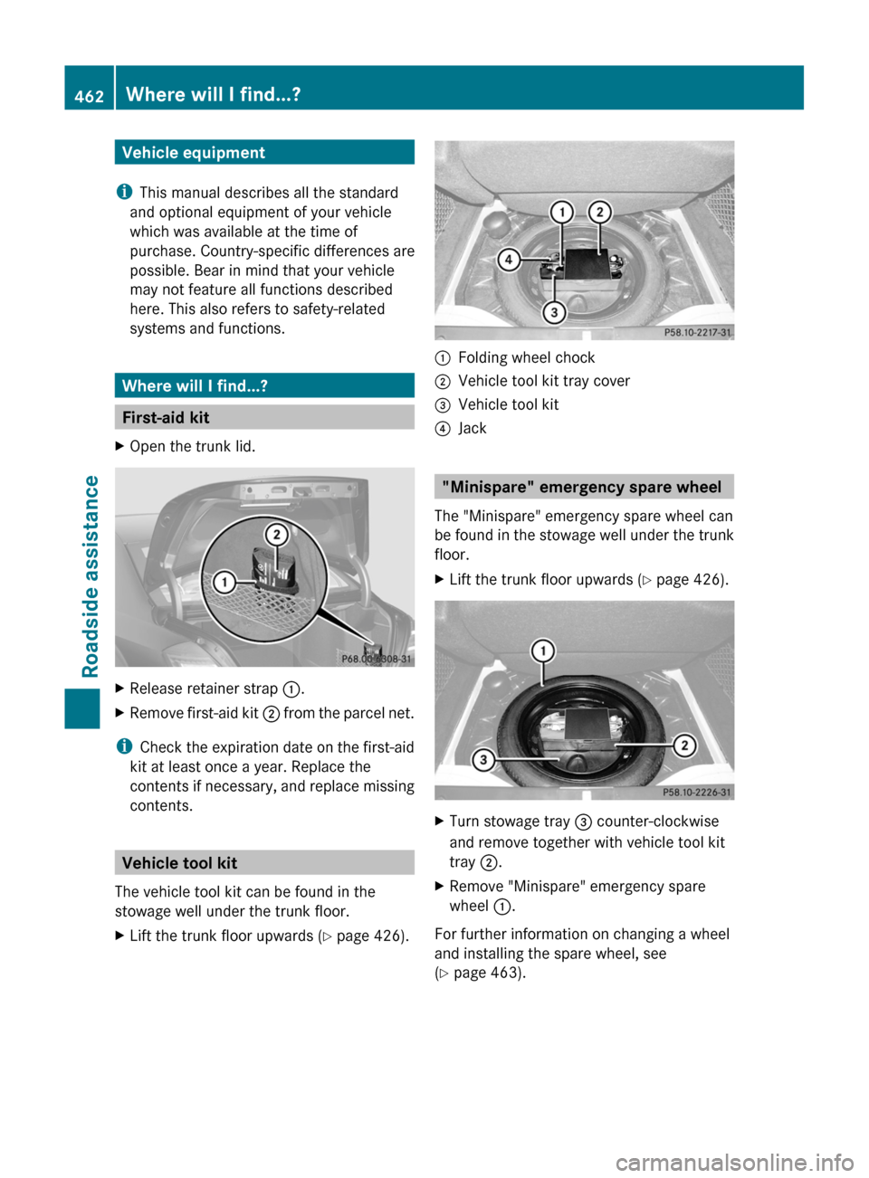
XOpen the trunk lid.XRelease retainer strap :.XRemove first-aid kit ; from the parcel net.
i
Check the expiration date on the first-aid
kit at least once a year. Replace the
contents if necessary, and replace missing
contents.
Vehicle tool kit
The vehicle tool kit can be found in the
stowage well under the trunk floor.
XLift the trunk floor upwards ( Y page 426).:Folding wheel chock;Vehicle tool kit tray cover=Vehicle tool kit?Jack
"Minispare" emergency spare wheel
The "Minispare" emergency spare wheel can
be found in the stowage well under the trunk
floor.
XLift the trunk floor upwards ( Y page 426).XTurn stowage tray = counter-clockwise
and remove together with vehicle tool kit
tray ;.XRemove "Minispare" emergency spare
wheel :.
For further information on changing a wheel
and installing the spare wheel, see
( Y page 463).
462Where will I find...?Roadside assistance
Page 466 of 524

XPrepare the vehicle as described
(Y page 463).
XRemove the following items from the
stowage well under the trunk floor:
XSecure the vehicle to prevent it from rolling
away.
Securing the vehicle to prevent it from
rolling away
GWarning
Only jack up the vehicle on level ground or on
slight inclines/declines. The vehicle could
otherwise fall off the jack and injure you or
others.
If your vehicle is equipped with a wheel chock,
it can be found in the vehicle tool kit
(Y page 462).
The folding wheel chock is an additional
securing measure to prevent the vehicle from
rolling away, for example when changing a
wheel.
XFold both plates upwards :.XFold out lower plate ;.XGuide the lugs on the lower plate fully into
openings in base plate =.
Securing the vehicle on level ground
XOn level ground: place chocks or other
suitable items under the front and rear of
the wheel that is diagonally opposite the
wheel you wish to change.
Securing the vehicle on slight downhill gradients
XOn downhill gradients: place chocks or
other suitable items in front of the wheels
of the front and rear axle.
Raising the vehicle
GWarning
When jacking up the vehicle, only use the jack
which has been specifically approved by
Mercedes-Benz for your vehicle.
The jack is designed exclusively for jacking up
the vehicle at the jacking points built into both
sides of the vehicle. The jack saddle must be
placed centrally under the jacking point. The
jack must always be vertical when in use,
especially on inclines or declines.
The jack is intended only for lifting the vehicle
briefly for wheel changes. It is not suited for
464Flat tireRoadside assistance
Page 469 of 524

! Always use wheel bolts : to fit the
"Minispare" emergency spare wheel with
light-alloy wheel. Using other wheel bolts
when fitting the "Minispare" emergency
spare wheel with light-alloy wheel could
damage the brake system.
Always use wheel bolts ; to fit the
"Minispare" emergency spare wheel with
steel wheel. Using other wheels when
fitting the "Minispare" emergency spare
wheel with steel wheel could damage the
brake system.
XClean the wheel and wheel hub contact
surfaces.
! To prevent damage to the paintwork, hold
the wheel securely against the wheel hub
while screwing in the first wheel bolt.
XSlide the emergency spare wheel onto the
alignment bolt and push it on.
XTighten the wheel bolts until they are
finger-tight.
XUnscrew the alignment bolt.XTighten the last wheel bolt until it is finger-
tight.
Lowering the vehicle
XTurn the crank of the jack counter-
clockwise until the vehicle is once again
standing firmly on the ground.
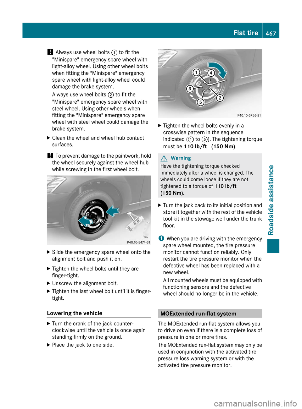
XPlace the jack to one side.XTighten the wheel bolts evenly in a
crosswise pattern in the sequence
indicated (: to A). The tightening torque
must be 110 lb/ft (150 Nm).
GWarning
Have the tightening torque checked
immediately after a wheel is changed. The
wheels could come loose if they are not
tightened to a torque of 110 lb/ft
(150 Nm).
XTurn the jack back to its initial position and
store it together with the rest of the vehicle
tool kit in the stowage well under the trunk
floor.
iWhen you are driving with the emergency
spare wheel mounted, the tire pressure
monitor cannot function reliably. Only
restart the tire pressure monitor when the
defective wheel has been replaced with a
new wheel.
All mounted wheels must be equipped with
functioning sensors and the defective
wheel should no longer be in the vehicle.
MOExtended run-flat system
The MOExtended run-flat system allows you
to drive on even if there is a complete loss of
pressure in one or more tires.
The MOExtended run-flat system may only be
used in conjunction with the activated tire
pressure loss warning system or with the
activated tire pressure monitor.
Flat tire467Roadside assistanceZ