2011 MERCEDES-BENZ R-Class spare tire
[x] Cancel search: spare tirePage 11 of 364

Flat tireChanging a wheel/mounting the
spare wheel ................................... 301
MOExtended run-flat system .........307
Preparing the vehicle .....................296
Raising the vehicle .........................303
TIREFIT kit ...................................... 297
Floormat ............................................. 276
Front fog lamp (display
message) ............................................ 223
Fuel Additives ........................................ 353
Notes ............................................. 352
Premium-grade unleaded gasoline . 352
Refueling ........................................ 160
Specifications ................................ 352
Troubleshooting ............................. 164
Fuel consumption
Current (on-board computer) .........211
Notes ............................................. 168
Fuel filler cap (display message) ..... 227
Fuel filler flap Emergency release ........................162
Opening/closing ............................ 162
Fuel filter (display message) ............ 227
Fuel level Calling up the range (on-board
computer) ...................................... 211
Fuses
Dashboard fuse box .......................316
Engine emergency stop .................317
Fuse allocation chart .....................315
Fuse box in the cargo
compartment ................................. 316
Fuse box in the engine
compartment ................................. 316
Notes ............................................. 315
G
Garage door opener Clearing the memory .....................275
Notes ............................................. 272
Opening/closing the garage door ..275
Programming the remote control ...273
Gear or selector lever (cleaning
guidelines) ......................................... 288
Genuine Mercedes-Benz parts ......... 348
Genuine wood trim and trim strips
(cleaning instructions) ...................... 288
Glove box ........................................... 247
GTW (Gross Trailer Weight)
(definition) ......................................... 341
H
Headlamp cleaning system .............. 119
Adding washer fluid .......................281
Notes ............................................. 357
Headlamp delayed switch-off
see Delayed switch-off, exterior lighting
Headlamp mode (daytime driving)
see Daytime running lamps
Headlamps
Cleaning ......................................... 286
Misting up ...................................... 120
Head restraint
Adjusting (electrically) ...................101
Head restraints
Adjusting (manually) ......................101
Adjusting (rear) .............................. 102
Installing/removing (rear) ..............102
Luxury ............................................ 101
see NECK-PRO head restraints/
NECK-PRO luxury head restraints
Heating
see Climate control
High beam flasher ............................. 119
Hill start assist .................................. 152
Hood Closing ........................................... 279
Opening ......................................... 278
Hydroplaning ..................................... 171
I
Immobilizer .......................................... 71
Indicator and warning lamps ABS ................................................ 239
Brakes ........................................... 236
DISTRONIC .................................... 243
Engine diagnostics .........................242
ESP ®
.............................................. 240
Fuel tank ........................................ 242
Reserve fuel ................................... 242
Seat belt ........................................ 237
Index9BA 251 USA, CA Edition A 2011; 1; 3, en-USd2sboikeVersion: 3.0.3.52010-04-16T14:31:55+02:00 - Seite 9
Page 71 of 364

GWarning
Never switch off the ESP®
when you see the
d warning lamp flashing in the instrument
cluster. In this case proceed as follows:
R When driving off, apply as little throttle as
possible.
R While driving, ease up on the accelerator
pedal.
R Adapt your speed and driving style to the
prevailing road conditions.
Failure to observe these guidelines could
cause the vehicle to skid. The ESP ®
cannot
prevent accidents resulting from excessive
speed.
! Only operate the vehicle for a maximum
of ten seconds on a brake test
dynamometer. Switch off the ignition.
Application of the brakes by ESP ®
may
otherwise destroy the brake system.
! Function or performance tests may only
be performed on a 2-axle dynamometer. If
you wish to operate the vehicle on such a
dynamometer, please consult an
authorized Mercedes-Benz Center
beforehand. You could otherwise damage
the drive train or the brake system.
i Only use wheels with the recommended
tire sizes. Only then will ESP ®
function
properly.
4ETS (Electronic Traction System)
GWarning
Observe "Important safety instructions"
( Y page 67).
Traction control is part of ESP ®
.
Traction control brakes the drive wheels
individually if they spin. This enables you to
pull away and accelerate on slippery surfaces,
for example if the road surface is slippery on
one side. In addition, more drive torque is
transferred to the wheel or wheels with
traction.
Traction control remains active, even if you
deactivate ESP ®
.
Deactivating/activating ESP ®GWarning
The ESP
®
should not be switched off during
normal driving other than in the
circumstances described below. Disabling
the system will reduce vehicle stability in
driving maneuvers.
Do not switch off the ESP ®
when a spare
wheel is mounted.
ESP ®
is activated automatically when the
engine is running.
It may be best to deactivate ESP ®
in the
following situations:
R when using snow chains
R in deep snow
R on sand or gravel
GWarning!
Activate ESP ®
as soon as the situations
described above no longer apply. ESP ®
will
otherwise not be able to stabilize the vehicle
if the vehicle starts to skid or a wheel starts
to spin.
When you deactivate ESP ®
:
R ESP ®
no longer improves driving stability.
R the engine's torque is no longer limited and
the drive wheels can spin. The spinning of
the wheels results in a cutting action, which
provides better grip.
R traction control is still activated.
R ESP ®
still provides support when you
brake.
If ESP ®
is deactivated and one or more wheels
start to spin, the d warning lamp in the
instrument cluster flashes. In such situations,
ESP ®
will not stabilize the vehicle.
Driving safety systems69SafetyBA 251 USA, CA Edition A 2011; 1; 3, en-USd2sboikeVersion: 3.0.3.52010-04-16T14:31:55+02:00 - Seite 69Z
Page 245 of 364

Driving systemsProblemPossible causes/consequences and M Solutions·
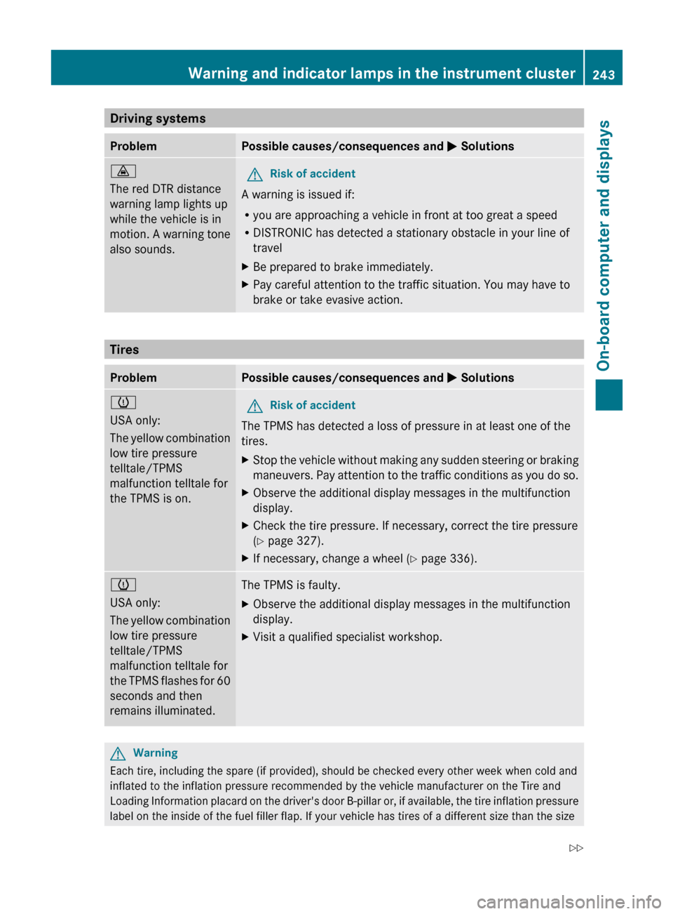
The red DTR distance
warning lamp lights up
while the vehicle is in
motion. A warning tone
also sounds.GRisk of accident
A warning is issued if:
R you are approaching a vehicle in front at too great a speed
R DISTRONIC has detected a stationary obstacle in your line of
travel
XBe prepared to brake immediately.XPay careful attention to the traffic situation. You may have to
brake or take evasive action.
Tires
ProblemPossible causes/consequences and M Solutionsh
USA only:
The yellow combination
low tire pressure
telltale/TPMS
malfunction telltale for
the TPMS is on.GRisk of accident
The TPMS has detected a loss of pressure in at least one of the
tires.
XStop the vehicle without making any sudden steering or braking
maneuvers. Pay attention to the traffic conditions as you do so.XObserve the additional display messages in the multifunction
display.XCheck the tire pressure. If necessary, correct the tire pressure
( Y page 327).XIf necessary, change a wheel ( Y page 336).h
USA only:
The yellow combination
low tire pressure
telltale/TPMS
malfunction telltale for
the TPMS flashes for 60
seconds and then
remains illuminated.The TPMS is faulty.XObserve the additional display messages in the multifunction
display.XVisit a qualified specialist workshop.GWarning
Each tire, including the spare (if provided), should be checked every other week when cold and
inflated to the inflation pressure recommended by the vehicle manufacturer on the Tire and
Loading Information placard on the driver's door B-pillar or, if available, the tire inflation pressure
label on the inside of the fuel filler flap. If your vehicle has tires of a different size than the size
Warning and indicator lamps in the instrument cluster243On-board computer and displaysBA 251 USA, CA Edition A 2011; 1; 3, en-USd2sboikeVersion: 3.0.3.52010-04-16T14:31:55+02:00 - Seite 243Z
Page 248 of 364

Vehicle equipment
i This manual describes all the standard
and optional equipment of your vehicle
which was available at the time of
purchase. Country-specific differences are
possible. Bear in mind that your vehicle
may not feature all functions described
here. This also refers to safety-related
systems and functions.
Loading guidelines
GWarning!
Always fasten items being carried as securely
as possible. Use cargo tie-down rings and
fastening materials appropriate for the weight
and size of the load.
In an accident, during hard braking or sudden
maneuvers, loose items will be thrown around
inside the vehicle. This can cause injury to
vehicle occupants unless the items are
securely fastened in the vehicle.
To help avoid personal injury during a collision
or sudden maneuver, exercise care when
transporting cargo. Do not pile luggage or
cargo higher than the seat backrests.
The cargo compartment is the preferred place
to carry objects. Always use cargo tie-down
rings, and if so equipped, always use the cargo
net when transporting cargo.
Never drive a vehicle with the tailgate open.
Deadly carbon monoxide (CO) gases may
enter vehicle interior resulting in
unconsciousness and death.
The gross vehicle weight (GVW) is the weight
of the vehicle including fuel, the vehicle tool
kit, spare tire, any installed accessories,
vehicle occupants and luggage/cargo.
The load limit and the gross vehicle weight
rating (GVWR) of your vehicle must never be
exceeded. The load limit and the GVWR are
stated on the vehicle identification plate on
the B-pillar on the driver's side
( Y page 330).
Additionally, the cargo must be distributed so
that the weight on each axle never exceeds
the maximum gross axle weight rating
(GAWR) for the front and rear axles. The data
on GVWR and GAWR is stated on the vehicle
identification plate on the B-pillar on the
driver's side ( Y page 330).
Further information can be found in the
"Loading the vehicle" section ( Y page 330).
The handling characteristics of a laden
vehicle are dependent on the distribution of
the load within the vehicle. For this reason,
you should observe the following notes when
transporting a load:
R Position heavy loads as far forwards as
possible and as low down in the cargo
compartment as possible.
R The load must not protrude above the
upper edge of the seat backrests.
R always place the load against the rear or
front seat backrests. Make sure that the
seat backrests are securely locked into
place.
R Hook in the cargo net when loading.
R Always place the load behind unoccupied
seats if possible.
R Secure the load with sufficiently strong and
wear-resistant tie down. Pad sharp edges
for protection.
Stowage compartments
Important safety guidelines
GWarning!
To help avoid personal injury during a collision
or sudden maneuver, exercise care when
storing objects in the vehicle. Put luggage or
cargo in the cargo compartment if possible.
Do not pile luggage or cargo higher than the
seat backrests.
246Stowage compartmentsLoading, stowing and features
BA 251 USA, CA Edition A 2011; 1; 3, en-USd2sboikeVersion: 3.0.3.52010-04-16T14:31:55+02:00 - Seite 246
Page 272 of 364

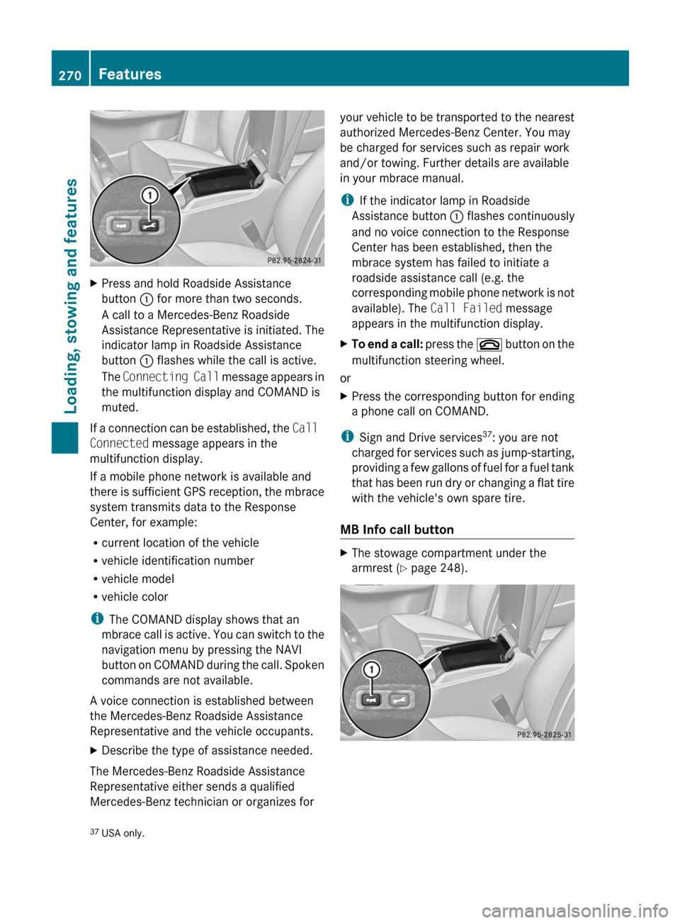
XPress and hold Roadside Assistance
button : for more than two seconds.
A call to a Mercedes-Benz Roadside
Assistance Representative is initiated. The
indicator lamp in Roadside Assistance
button : flashes while the call is active.
The Connecting Call message appears in
the multifunction display and COMAND is
muted.
If a connection can be established, the Call
Connected message appears in the
multifunction display.
If a mobile phone network is available and
there is sufficient GPS reception, the mbrace
system transmits data to the Response
Center, for example:
R current location of the vehicle
R vehicle identification number
R vehicle model
R vehicle color
i The COMAND display shows that an
mbrace call is active. You can switch to the
navigation menu by pressing the NAVI
button on COMAND during the call. Spoken
commands are not available.
A voice connection is established between
the Mercedes-Benz Roadside Assistance
Representative and the vehicle occupants.
XDescribe the type of assistance needed.
The Mercedes-Benz Roadside Assistance
Representative either sends a qualified
Mercedes-Benz technician or organizes for
your vehicle to be transported to the nearest
authorized Mercedes-Benz Center. You may
be charged for services such as repair work
and/or towing. Further details are available
in your mbrace manual.
i If the indicator lamp in Roadside
Assistance button : flashes continuously
and no voice connection to the Response
Center has been established, then the
mbrace system has failed to initiate a
roadside assistance call (e.g. the
corresponding mobile phone network is not
available). The Call Failed message
appears in the multifunction display.XTo end a call: press the ~ button on the
multifunction steering wheel.
or
XPress the corresponding button for ending
a phone call on COMAND.
i Sign and Drive services 37
: you are not
charged for services such as jump-starting,
providing a few gallons of fuel for a fuel tank
that has been run dry or changing a flat tire
with the vehicle's own spare tire.
MB Info call button
XThe stowage compartment under the
armrest ( Y page 248).37
USA only.270FeaturesLoading, stowing and features
BA 251 USA, CA Edition A 2011; 1; 3, en-USd2sboikeVersion: 3.0.3.52010-04-16T14:31:55+02:00 - Seite 270
Page 296 of 364

Vehicle tool kit
Notes
The vehicle tool kit can be found in the
stowage well under the cargo compartment
floor.
i Vehicles are not equipped with the tools
needed to change a wheel when they leave
the factory, e.g. jack or lug wrench. Some
tools for changing a wheel are specific to
the vehicle. To obtain tools approved for
your vehicle, visit a qualified specialist
workshop, e.g. an authorized Mercedes-
Benz Center.
Folding the cargo compartment floor up
XPress release handle ; in the direction of
the arrow.XLift cargo compartment floor : up by
release handle ;.XFold out hook = on the underside of the
cargo compartment floor.XAttach hook = to upper seal ? in the
cargo compartment.
Vehicles with a TIREFIT kit
XLift the cargo compartment floor up
( Y page 294).:Lug wrench;Towing eye=Alignment bolt?JackAFolding wheel chockBFuse allocation chartCRatchet ring spanner
Vehicles with collapsible spare wheel
XLift the cargo compartment floor up
( Y page 294).294Where will I find...?Roadside Assistance
BA 251 USA, CA Edition A 2011; 1; 3, en-USd2sboikeVersion: 3.0.3.52010-04-16T14:31:55+02:00 - Seite 294
Page 298 of 364

iFully deflating the tire can take a few
minutes.XScrew the valve insert back into the valve.XScrew the valve cap back on.
In the spare wheel well, there are two
guides : to keep the collapsible spare wheel
in place.
XLay collapsible spare wheel ; in the
emergency spare wheel well.
i Make sure that collapsible spare
wheel ; is positioned on guides :
precisely.
XLay the tool holder in collapsible spare
wheel ; so that the electric air pump is
pointing towards the tailgate (Y page 294).XTurn the tool holder approximately 180°,
so that the electric air pump points
forwards.
The tool holder should now be positioned
in accordance with the instructions on the
installation position.XTurn the retainer screw on the collapsible
spare wheel clockwise into the tool holder
as far as it will go.XStow the jack in the vehicle tool kit.
Flat tire
Preparing the vehicle
Your vehicle may be equipped with a
collapsible spare wheel or the MOExtended
run-flat system ( Y page 307).
i Vehicle preparation is not necessary on
vehicles with the MOExtended run-flat
system.
i Vehicles featuring the MOExtended run-
flat system are not equipped with the
TIREFIT kit. It is therefore recommended
that you additionally equip your vehicle
with the TIREFIT kit if you mount tires that
do not feature run-flat properties, e.g.
winter tires. You can obtain a TIREFIT kit
from an authorized Mercedes-Benz Center,
for example.
XVehicles with the AIRMATIC package: make
sure that highway level is selected
( Y page 183).XStop the vehicle as far away as possible
from traffic on solid, non-slippery and level
ground.XSwitch on the hazard warning lamps.XFirmly depress the parking brake.XBring the front wheels into the straight-
ahead position.XMove the DIRECT SELECT lever to P.XSwitch off the engine.296Flat tireRoadside Assistance
BA 251 USA, CA Edition A 2011; 1; 3, en-USd2sboikeVersion: 3.0.3.52010-04-16T14:31:55+02:00 - Seite 296
Page 303 of 364

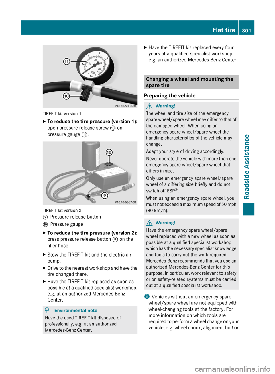
TIREFIT kit version 1
XTo reduce the tire pressure (version 1):
open pressure release screw F on
pressure gauge G.
TIREFIT kit version 2
EPressure release buttonFPressure gaugeXTo reduce the tire pressure (version 2):
press pressure release button E on the
filler hose.
XStow the TIREFIT kit and the electric air
pump.
XDrive to the nearest workshop and have the
tire changed there.
XHave the TIREFIT kit replaced as soon as
possible at a qualified specialist workshop,
e.g. at an authorized Mercedes-Benz
Center.
HEnvironmental note
Have the used TIREFIT kit disposed of
professionally, e.g. at an authorized
Mercedes-Benz Center.
XHave the TIREFIT kit replaced every four
years at a qualified specialist workshop,
e.g. an authorized Mercedes-Benz Center.
Changing a wheel and mounting the
spare tire
Preparing the vehicle
GWarning!
The wheel and tire size of the emergency
spare wheel/spare wheel may differ to that of
the damaged wheel. When using an
emergency spare wheel/spare wheel the
handling characteristics of the vehicle may
change.
Adapt your style of driving accordingly.
Never operate the vehicle with more than one
emergency spare wheel/spare wheel that
differs in size.
Only use an emergency spare wheel/spare
wheel of a differing size briefly and do not
switch off ESP®.
When using an emergency spare wheel, you
must not exceed a maximum speed of 50 mph
(80 km/h).
GWarning!
Have the emergency spare wheel/spare
wheel replaced with a new wheel as soon as
possible at a qualified specialist workshop
which has the necessary specialist knowledge
and tools to carry out the work required.
Mercedes-Benz recommends that you use an
authorized Mercedes-Benz Center for this
purpose. In particular, work relevant to safety
or on safety-related systems must be carried
out at a qualified specialist workshop.
iVehicles without an emergency spare
wheel/spare wheel are not equipped with
wheel-changing tools at the factory. For
more information on which tools are
required to perform a wheel change on your
vehicle, e.g. wheel chock, alignment bolt or
Flat tire301Roadside AssistanceBA 251 USA, CA Edition A 2011; 1; 3, en-USd2sboikeVersion: 3.0.3.52010-04-16T14:31:55+02:00 - Seite 301Z