2011 MERCEDES-BENZ M-CLASS SUV phone
[x] Cancel search: phonePage 315 of 389

the separate mobil
ephone operating
instructions).
Sliding adapte rfor mobil ephone
bracket 21 Certain mobil
ephone brackets require aslid-
ing adapter so the bracket can be installed
correctly. :
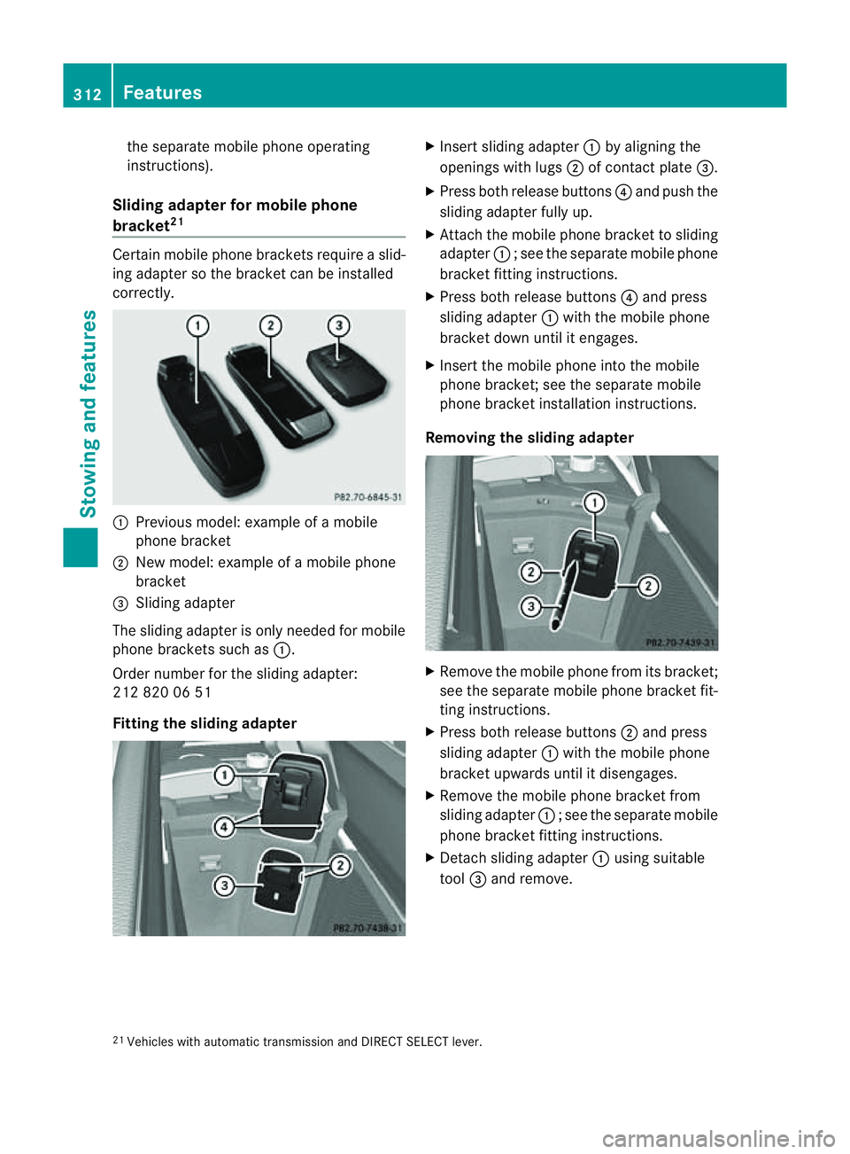
Previou smodel :examp leof am obile
phone bracket
; New model :examp leof am obile phone
bracket
= Sliding adapter
The sliding adapter is only neede dfor mobile
phone brackets such as :.
Order number for the sliding adapter:
212 820 06 51
Fittin gthe sliding adapter X
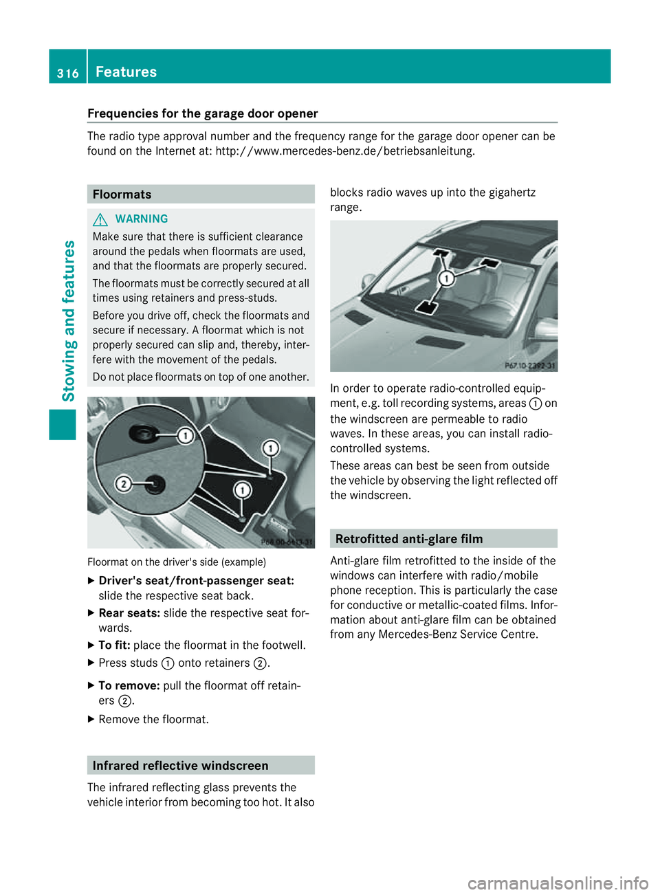
Insert sliding adapter :by aligning the
openings wit hlugs ;of contact plate =.
X Press both release buttons ?and push the
sliding adapter fully up.
X Attach the mobile phone bracket to sliding
adapter :;see the separate mobile phone
bracket fit ting instructions.
X Pres sboth release buttons ?and press
slidin gadapter :with the mobile phone
bracket down unti litengages.
X Insert the mobil ephone int othe mobile
phone bracket ;see the separate mobile
phone bracket installation instructions.
Removing th esliding ada pter X
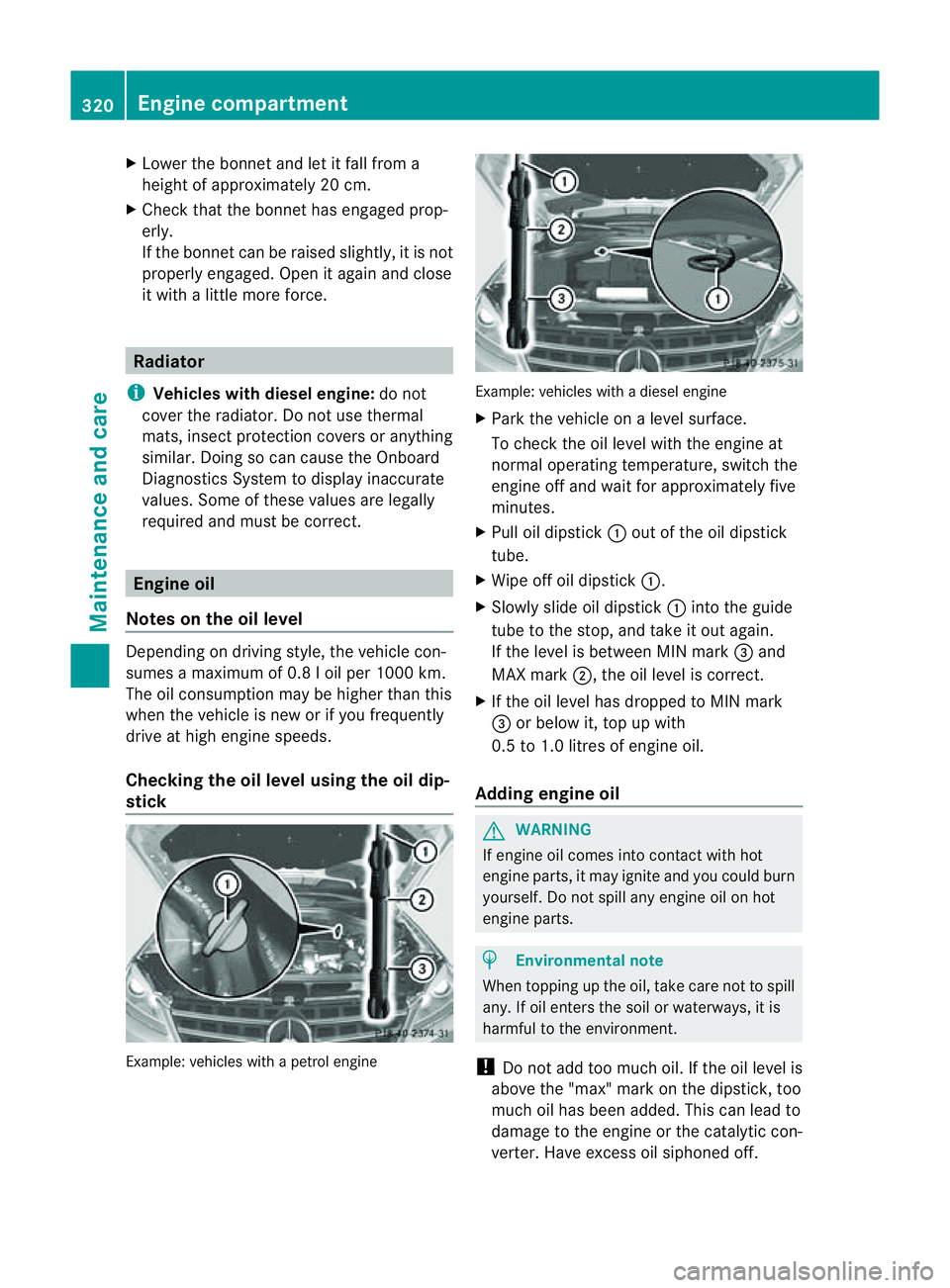
Remove the mobile phone from its bracket;
see the separate mobile phone bracket fit-
ting instructions.
X Press both release buttons ;and press
sliding adapter :with the mobile phone
bracket upwards until it disengages.
X Remove the mobile phone bracket from
sliding adapter :;see the separate mobile
phone bracket fit ting instructions.
X Detach sliding adapter :using suitable
tool =and remove.
21 Vehicles with automatic transmission and DIRECT SELECT lever. 312
FeaturesStowin
gand features
Page 319 of 389

Frequencies for th
egarage doo ropener Th
er adio typ eapproval number and th efrequency range for th egarag edoor opener can be
fou ndonthe Interne tat: http://www.mercedes-benz.de/betriebsanleitung. Floormats
G
WARNING
Make sure that there is sufficient clearance
around the pedals when floormats are used,
and that the floormats are properly secured.
The floormats must be correctly secured at all
times using retainer sand press-studs.
Before you drive off ,chec kthe floormats and
secur eifnecessary. Afloormat which is not
properly secured can slip and, thereby, inter-
fere with the movemen tofthe pedals.
Do not plac efloormats on top of one another. Floormat on the driver's side (example)
X
Driver's seat/front-passenger seat:
slide the respective seat back.
X Rear seats: slide the respective seat for-
wards.
X To fit: place the floorma tinthe footwell.
X Press studs :ontoretainers ;.
X To remove: pull the floormat off retain-
ers ;.
X Remov ethe floormat. Infrared reflective windscreen
The infrared reflecting glass prevents the
vehicle interior from becoming too hot. It also blocks radio waves up int
othe gigahertz
range. In orde
rtooperateradio-controlled equip-
ment, e.g. toll recording systems, areas :on
the windscreen are permeable to radio
waves. In these areas, you can install radio-
controlled systems.
Thes earea scan best be seen from outside
the vehicle by observing the light reflected off
the windscreen. Retrofitted anti-glar
efilm
Anti-glar efilm retrofitted to the inside of the
windows can interfer ewith radio/mobile
phone reception. This is particularly the case
for conductive or metallic-coated films. Infor-
mation about anti-glar efilm can be obtained
from any Mercedes-Ben zService Centre. 316
FeaturesStowing and features
Page 323 of 389

X
Lower th ebonnet and let it fal lfrom a
heig ht of approx imately 20 cm.
X Check that the bonnet has engaged prop-
erly.
If the bonnet can be raised slightly, it is not
properly engaged. Open it again and close
it with alittle more force. Radiator
i Vehicles with diesel engine: do not
cover the radiator .Don ot use thermal
mats, insec tprotectio ncover sora nything
similar. Doing so can cause the Onboard
Diagnosti csSystem to display inaccurate
values .Some of these values ar elegally
required and must be cor rect. Engine oil
Notes on the oil level Depending on driving style, the vehicle con-
sume samaximum of 0.8 loil per 100 0km.
Th eo il consumption may be higher than this
when the vehicle is new or if you frequently
drive at high engin espeeds.
Checking the oil level using the oil dip-
stick Example: vehicles with
apetro lengine Example: vehicle
swithadiesel engine
X Park the vehicle on alevel surface.
To chec kthe oil level with the engin eat
normal operating temperature, switch the
engine off and wait for approximately five
minutes.
X Pull oil dipstick :out of the oil dipstick
tube.
X Wip eoff oi ldipstick :.
X Slowly slide oil dipstick :into the guide
tube to the stop, and take it out again.
If the level is between MIN mark =and
MAX mark ;,the oil level is correc t.
X If th eoil level has dropped to MIN mark
= or below it, top up with
0.5 to 1.0 litres of engine oil.
Adding engine oil G
WARNING
If engine oil comes into contact with hot
engine parts, it may ignite and you could burn
yourself .Donot spill any engin eoil on hot
engine parts. H
Environmental note
When topping up the oil, take care not to spill
any. If oil enters the soil or waterways, it is
harmful to the environment.
! Do not add too much oil. If the oil level is
above the "max" mar konthe dipstick ,too
much oil has been added. This can lead to
damage to the engin eorthe catalytic con-
verter .Have excess oil siphoned off. 320
Eng
inecompartmentMaintenance and care
Page 326 of 389

Maintainin
gthe time-dependen tservice
schedule:
X Not edown the service due date displayed
in the multifunc tion display befor ediscon-
necting the battery.
or
X Subtract the battery disconnection periods
from the servic edate shown on the displ ay
after reconnecting the battery.
i The ASSYST PLUS service interval displ ay
does not show any information on the
engine oil level .Observ ethe notes on the
engin eoil level (Y page 320).
Hiding aservice message X
Pres sthe % ora button on th esteer-
ing wheel.
Displaying service messages X
Switch th eignitio non.
X Press =or; on the steering wheel
to select the Serv. menu.
X Press 9or: to select the ASSYST PLUS submenu and press
ato confirm.
The service du edatea ppears in the multi-
function display.
Points to remember Resettin
gthe ASSYS TPLUS service inter-
val display
Aq ualified specialist workshop, e.g. a
Mercedes -Ben zS ervice Cent re,w ill reset the
ASSYST PLU Sservic einterval display after
the service work has bee ncarried out.
You can obtain further information ,e.g.
regarding servic ework,from aMercedes-
Benz Ser vice Centre or directly from
Mercedes-Benz.
! If the ASSYST PLUS servic einterval dis-
play has bee ninadvertently reset, this set-
ting can be corrected at aMercedes-Benz
Ser vice Centre. Have servic
ework carried out as described
in the Ser vice Boo klet. This may otherwise
lead to inc reased wear and damage to the
major assemblies or the vehicle.
Driving abroad
An extensive Mercedes -Ben zS ervice network
is also available in other coun tries. The
Service Hotline's curren ttelephone numbers
for use when you are abroa dare to be found
in th e"Mercedes-Ben zService24h" section
of the Ser vice Boo klet. AdBlue
®
service indicator
i For BlueTE Cvehicles only.
The BlueTE Cexhaus tgas aftertreatment
must be operated with the reducing agent
AdBlue ®
in order for it to function correctly.
Under normal operating conditions, afull tank
of AdBlue ®
should last until the nex tservice
due date.
Depending on how and where the vehicle is
used, there may be an inc rease in the
AdBlue ®
consumption, resulting in the next
servic edue date being brought forward.
Certain display messages sho wthat
AdBlue ®
must be topped up, e.g.
Refill AdBlue at worksh opSee Owner’s Manual
Refill AdBlue at worksho
pNostart in .. km
Aw
arning signal also sounds.
You can no longer star tthe engin ewhen the
AdBlue ®
supply has been used up
(Y page 268).
Top up AdBlue ®
(Y page 157).
Before taking atripw ithy our vehicle outside
Europe, have th eAdBlue ®
suppl ychec kedat
aq ualified specialist workshop. If necessary,
have the AdBlue ®
topped up. Before using
your vehicle for an extended period in coun-
tries outside Europe, con tact aq ualified spe-
cialist workshop.
Obser vethe note sonAdBlue®
(Y page 374). Maintenance
323Maintenanceand care Z
Page 365 of 389

tyre is penetrated by
aforeign object .Inthe
event of asudden loss of pressure, bring the
vehicl etoah altbyb rakingcarefully. Do not
make any sudden steering movements when
doing so.
Informatio nontyre pressures is displayed in
the multifunction display. After afew minutes
of driv ing, the curren ttyre pressure of each
tyre is sho wn inthe multifunction display.
i Thet yre pressure values indicated by the
on-board computer may differ from those
measured at afilling station with apressure
gauge. Th etyre pressures shown by the on-
board computer refer to thos emeasured at
sea level. At high altitudes, the tyr epres-
sure values indicated by apressure gauge
are higher than thos eshown by the on-
boar dcomputer .Inthis case ,donot reduce
the tyr epressures.
i Theo peration of the tyr epressure moni-
to rc an be affected by interference from
radio transmitting equipment (e.g. radio
headphones ,two-way radios) that may be
being operated in or near the vehicle.
Checking tyr epressure electronically X
Make sure that the key is in position 2
(Y page 139) in the ignitio nlock.
X Press the =or; button on the steer-
ing wheel to select the Serv. menu.
X Press the 9or: button to select
Tyre pressure .
X Press the abutton.
The curren ttyre pressure for each wheel
will be displayed in the multifunction dis-
play.
If the vehicle has been parked for longe rthan
20 minutes, the Tyre pressures will be
displaye
dafter afew minutes of driving message appe
ars.
After ateach-in period, the tyr epressure
monito rautomatically recognise snew
wheels or new sensors. As long as aclear
allocation of the tyre pressure values to the individual wheels is not possible
,the Tyre pressure monito
ractive displa
ymes-
sage is shown instead of the tyr epressure
display. Th etyre pressures are already being
monitored.
i Ifas pare wheel/emergenc yspare wheel
is fitted, the system may continue to show
the tyr epressure of th ewheel that has
been removed for afew minutes. If this
occurs, note that the value displayed for
the position where the spare wheel/emer-
gency spare wheel is fitted is not the same
as the spare wheel/emergenc yspare
wheel's current tyr epressure.
Tyre pressure monito rwarning mes-
sages If the tyre pressure monitor detects
asignifi-
cant pressure loss on one or more tyres, a
warnin gmessage is shown in the multifunc-
tion display. Awarning ton ealso sounds and
th et yrep ressure warning lamp ligh tsup in
the instrumen tcluster.
Eac htyret hat is affected by asignificant loss
of pressure is highlighted in th epressure dis-
play.
If the Please correc ttyrep ressure messag
eappear sinthe multifunctio ndis-
play:
X Chec kthe tyr epressure on all fou rwheels
and correc titifn ecessary.
i If the wheel positions on the vehicle are
inter changed, the tyre pressures may be
displ ayed for th ewrong positions for a
short time .This is rectified after afew
minutes of driving, and the tyr epressures
are displayed for th ecorrect positions.
Restarting th etyre pressure monitor When yo
urestar tthe tyr epressure monitor,
all existing warning message sare deleted and
th ew arning lamps go out. The monitor uses
the currently set tyre pressures as the refer-
ence values for monitoring. In most cases, the
tyre pressure monitor will automatically 362
Tyr
epressureWheels and tyres
Page 374 of 389

H
Environmenta
lnote
Daimler AG also supplies reconditioned
assemblies and part swhicha re of the same
quality as new parts. For these, the same war-
ranty applie sasfor new par ts.
Always spe cify the vehicle identificatio nnum-
ber (VIN )(Y page 372) and th eengine num-
ber (Y page373)w hen orderi nggenuine
Mercedes-Ben zparts. Vehicle electronics
Tampering with th
eengine electron-
ics G
WA
RNING
Only have work on the engin eelectronics and
related component scarried out at aqualified
specialist workshop which has the necessary
specialist knowledge and tools to carry out
the work required .Mercedes-Ben zrecom-
mends that you use aMercedes-Ben zService
Centr efor this purpose. In particular ,work
relevant to safet yoronsafety-related sys-
tems must be carried out at aqualified spe-
cialist workshop .Otherwise, the vehicle's
roadworthiness could be affected.
! Only have maintenanc ework on the
engin eelectronics and its associated parts,
such as control units, sensor sand connec-
tor leads, carried out at aqualified special-
ist workshop, e.g. aMercedes-Benz Ser vice
Centre. Vehicle compo nentsm ay other-
wise wear mor equickly and the vehicle's
operatin gpermit may be invalidated. Retrofitting of two-way radios and
mobile phones (RF transmitters)
Use th eTechnical Specification
ISO/TS 21609 30
implementation regulation
when retrofitting RF (radi ofrequency) trans-
mitters. If your vehicle has fittings for two-way radio
equipment, use th
epower supply or aerial
connection sintended for use with the basic
wiring. Be sure to obser vethe manufacturer's
additional instructions when installing the fit-
tings.
! Hav eaftermarket radi ofrequency trans-
mittin gequipmen tinstalled at aquali fied
sp ec ialist worksho p. Mercedes-Benz rec-
ommends that you use aMercedes-Benz
Ser vice Centre for thi spurpose.
The transmission output at the aerial base
must not exceed the maximum values below. Waveband Maximum trans-
mission output
(PEAK)
Short wave
(f
<54M Hz) 100 W
4mw
aveband 30 W
2mw
aveband 50 W
Trunked radio/Tetra 35 W
70 cm waveband 35 W
GSM 900/AMPS 10 W
GSM 1800 10 W
UMTS 10 W
The following aerial positions may be used if
RF transmitters have been properly installed:
30 ISO/TS 216 09–Technical Specification for Road Vehicles (EMC) guidelines for installation of aftermarket
radio frequenc ytransmitting equipment. Vehicle electronics
371Technicaldata Z