2011 MERCEDES-BENZ GL service reset
[x] Cancel search: service resetPage 16 of 376

Emergency Tensioning Devices ........ 57
Fastening ......................................... 55
Important safety guidelines .............53
Releasing ......................................... 57
Safety guidelines ............................. 37
Switching belt adjustment on/off
(on-board computer) ......................225
Warning lamp ................................. 255
Warning lamp (function) ................... 57
Seat heating
Indicator lamp (Malfunction) ..........105
Seats
Adjusting (electrically) .....................96
Adjusting (second and third rows) . 100
Adjusting the 4-way lumbar
support .......................................... 104
Adjusting the head restraint ............97
Cleaning the cover .........................304
Correct driver's seat position ........... 94
Important safety instructions ...........95
Multicontour seat .......................... 103
Storing settings (memory
function) ........................................ 110
Switching seat heating on/off .......104
Switching the seat ventilation on/
off .................................................. 105
Seat ventilation
Indicator lamp (Malfunction) ..........105
Securing hooks .................................. 268
Sensors (cleaning instructions) ....... 303
Service indicator see Service interval display
Service interval display .................... 298
Displaying a service message (on-
board computer) ............................ 299
Service products
AdBlue ®
special additives ..............367
Brake fluid ..................................... 369
Coolant (engine) ............................ 369
Engine oil ....................................... 368
Filling capacity ............................... 365
Fuel ................................................ 366
Important safety notes ..................364
Notes ............................................. 364
Refrigerant (air-conditioning
system) .......................................... 369
Washer fluid ................................... 370Settings
Factory (on-board computer) .........221
On-board computer .......................221
Shift ranges ....................................... 155
Side impact air bag ............................. 41
Side marker lamp (display
message) ............................................ 239
Side windows Convenience closing feature ............87
Convenience opening feature ..........86
Hinged side windows .......................86
Important safety information ...........84
Opening/closing .............................. 85
Resetting ......................................... 87
Troubleshooting ............................... 88
Sliding sunroof
Important safety information ...........88
Troubleshooting ............................... 90
see Tilt/sliding sunroof
SmartKey
Changing the battery .......................76
Changing the programming .............75
Checking the battery .......................76
Important safety notes ....................72
Malfunction ...................................... 77
Snow chains ...................................... 172
Socket ................................................ 281
Dashboard ..................................... 281
Front-passenger footwell ...............281
Luggage compartment ...................281
Rear compartment .........................281
SOS
see mbrace
Spare wheel
Notes/data .................................... 359
Storage location ............................ 311
see Emergency spare wheel
Speedometer
Additional speedometer (on-
board computer) ............................ 218
Segments ...................................... 215
Setting the unit (on-board
computer) ...................................... 221
SRS (Supplemental Restraint
System) Display message ............................ 231
Introduction ..................................... 3614IndexBA 164.8 USA, CA Edition B 2011; 1; 2, en-USd2sboikeVersion: 3.0.3.52010-04-21T15:08:44+02:00 - Seite 14
Page 18 of 376

Outside temperature ...................... 214
Setting ........................................... 139
Theft deterrent locking system
Immobilizer ...................................... 69
Tilt/sliding sunroof
Opening/closing .............................. 89
Resetting ......................................... 90
Time (on-board computer) ................ 222
TIREFIT kit .......................................... 312
Tire pressure Calling up (on-board computer) .....341
Checking manually ........................339
Display message ............................ 248
Maximum ....................................... 344
Notes ............................................. 337
Not reached (TIREFIT) ....................315
Pressure loss warning ....................339
Reached (TIREFIT) ..........................315
Recommended ............................... 336
Tire pressure monitor
Warning lamp ................................. 260
Tire pressure monitoring system
Function/notes ............................. 341
Restarting ...................................... 343
Tires
Aspect ratio (definition) .................356
Average weight of the vehicle
occupants (definition) ....................354
Bar (definition) ............................... 354
Characteristics .............................. 354
Checking ........................................ 335
Cleaning ......................................... 336
Definition of terms .........................354
Direction of rotation ......................348
Distribution of the vehicle
occupants (definition) ....................357
DOT, Tire Identification Number
(TIN) ............................................... 353
DOT (Department of
Transportation) (definition) ............354
Flat tire .......................................... 311
GAWR (Gross Axle Weight Rating)
(definition) ..................................... 355
GTW (Gross Trailer Weight)
(definition) ..................................... 355
Guidelines to be observed .............335
GVW (Gross Vehicle Weight)
(definition) ..................................... 355GVWR (Gross Vehicle Weight
Rating) (definition) .........................355
Increased vehicle weight due to
optional equipment (definition) ......354
Kilopascal (kPa) (definition) ...........355
Labeling (overview) ........................350
Load bearing index (definition) ......356
Load index ..................................... 353
Load index (definition) ...................355
Maximum loaded vehicle weight
(definition) ..................................... 355
Maximum load on a tire
(definition) ..................................... 356
Maximum permissible tire
pressure (definition) ....................... 355
Maximum tire load .........................348
Maximum tire loading (definition) ..355
Optional equipment weight
(definition) ..................................... 356
PSI (pounds per square inch)
(definition) ..................................... 356
Replacing ....................................... 350
Service life ..................................... 335
Sidewall (definition) .......................356
Speed index (definition) .................355
Storing ........................................... 336
Structure and characteristics
(definition) ..................................... 354
Temperature .................................. 349
TIN (Tire Identification Number)
(definition) ..................................... 356
Tire bead (definition) ......................356
Tire pressure (definition) ................356
Tire pressures (recommended) ......354
Tire quality classes ........................348
Tire size (data) ............................... 357
Tire size designation, load-bearing
capacity, speed index ....................351
Tire tread ....................................... 335
Tire tread (definition) .....................356
Total load limit (definition) .............357
Traction ......................................... 349
Traction (definition) .......................356
Tread wear ..................................... 349
TWR (permissible trailer drawbar
noseweight) (definition) .................356
Uniform tire quality classification
standards (definition) .....................35416IndexBA 164.8 USA, CA Edition B 2011; 1; 2, en-USd2sboikeVersion: 3.0.3.52010-04-21T15:08:44+02:00 - Seite 16
Page 54 of 376

of having to swerve to avoid an obstacle at
a speed above 85 mph (140 km/h).
PRE-SAFE ®
takes the following measures
depending on the hazardous situation
detected:
R the front seat belts are pre-tensioned.
R on vehicles with memory functions: the
front-passenger seat is adjusted if it is in an
unfavorable position under accident
conditions.
R if the vehicle skids, the side windows are
closed so that only a small gap remains.
R on vehicles with sliding sunroof: if the
vehicle skids, the sliding sunroof closes so
that only a small gap remains.
If the hazardous situation passes without
resulting in an accident, PRE-SAFE ®
slackens
the belt pretensioning. All settings made by
PRE-SAFE ®
can then be reversed.
If the seat belts are not released:XMove the backrest or the seat back slightly
until the belt pretensioning is reduced.
The locking mechanism releases.GWarning
Make sure that nobody can become trapped
as you adjust the seat.
! Make sure that there are no objects in the
footwell or behind the seats when resetting
the seats. There is a risk that the seats
and/or the objects could be damaged.
More information about belt adjustment, a
convenience function integrated into PRE-
SAFE ®
, can be found in the "Belt adjustment"
section ( Y page 56).
NECK-PRO head restraints
The NECK-PRO head restraints increase
protection to the driver's and front-
passenger's head and neck. To this end, the
head restraints on the driver's and front-
passenger seats are moved forwards and
upwards in the event of a rear-end collision of
a certain severity. This provides better head
support.GWarning
Do not secure any objects (e.g. coat hangers)
on the NECK-PRO head restraints. Otherwise,
the NECK-PRO head restraints may not
function properly, or in the event of a rear-end
collision may not be able offer the level of
protection they are designed to provide.
If the NECK-PRO head restraints have been
triggered in an accident, you must reset the
NECK-PRO head restraints on the driver’s and
front-passenger seat ( Y page 52).
Otherwise, the additional protection will not
be available in the event of another rear-end
collision. You can recognize when NECK-PRO
head restraints have been triggered by the
fact that they have moved forwards and can
no longer be adjusted.
Resetting triggered NECK-PRO head
restraints
Important safety information
GWarning
For reasons of safety, have the NECK-PRO
head restraints/NECK-PRO luxury head
restraints checked at a Mercedes-Benz
Service Center after a rear-end collision.
GWarning
If you press the NECK-PRO head restraint
cushion backwards, make sure that your
fingers are not trapped between the cushion
and the cover. Failure to observe could result
in injuries.
NECK-PRO head restraints
i Resetting the NECK-PRO head restraints
requires a certain amount of strength. If
you have difficulty resetting the NECK-PRO
head restraints, have this work carried out
at a qualified specialist workshop, e.g. an
authorized Mercedes-Benz Center.
52Occupant safetySafety
BA 164.8 USA, CA Edition B 2011; 1; 2, en-USd2sboikeVersion: 3.0.3.52010-04-21T15:08:44+02:00 - Seite 52
Page 220 of 376

FunctionETrip computer menu (Y page 227)FTelephone menu (Y page 227)Standard display menu
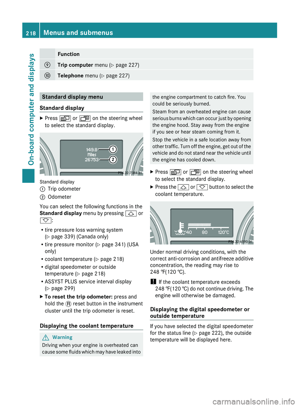
Standard displayXPress V or U on the steering wheel
to select the standard display.
Standard display
:Trip odometer;Odometer
You can select the following functions in the
Standard display menu by pressing & or
* :
R tire pressure loss warning system
( Y page 339) (Canada only)
R tire pressure monitor ( Y page 341) (USA
only)
R coolant temperature ( Y page 218)
R digital speedometer or outside
temperature ( Y page 218)
R ASSYST PLUS service interval display
( Y page 299)
XTo reset the trip odometer: press and
hold the . reset button in the instrument
cluster until the trip odometer is reset.
Displaying the coolant temperature
GWarning
Driving when your engine is overheated can
cause some fluids which may have leaked into
the engine compartment to catch fire. You
could be seriously burned.
Steam from an overheated engine can cause
serious burns which can occur just by opening
the engine hood. Stay away from the engine
if you see or hear steam coming from it.
Stop the vehicle in a safe location away from
other traffic. Turn off the engine, get out of the
vehicle and do not stand near the vehicle until
the engine has cooled down.XPress V or U on the steering wheel
to select the standard display.XPress the & or * button to select the
coolant temperature.
Under normal driving conditions, with the
correct anti-corrosion and antifreeze additive
concentration, the reading may rise to
248 ‡(120 †).
! If the coolant temperature exceeds
248 ‡(120 †) do not continue driving. The
engine will otherwise be damaged.
Displaying the digital speedometer or
outside temperature
If you have selected the digital speedometer
for the status line ( Y page 222), the outside
temperature will be displayed here.
218Menus and submenusOn-board computer and displays
BA 164.8 USA, CA Edition B 2011; 1; 2, en-USd2sboikeVersion: 3.0.3.52010-04-21T15:08:44+02:00 - Seite 218
Page 301 of 376

The service interval display informs you of the
next service due date.
If a service due date has been exceeded, you
also hear an acoustic signal.
The multifunction display shows a service
message for a few seconds, e.g.
Service A In .. Miles
Service A due now
Service A Exceeded By .. Miles
The letter indicates how much time the
workshop will require to carry out the service
work. The letters displayed range from A for
a short service duration to H for a long service
duration.
The service interval display does not take into
account any periods of time during which the
battery is disconnected.
Maintaining the time-dependent service
schedule:XNote down the service due date displayed
in the multifunction display before
disconnecting the battery.
or
XSubtract the battery disconnection periods
from the service date shown on the display
after reconnecting the battery.
Hiding the service message
XPress the . reset button on the
instrument cluster ( Y page 28).
Displaying the service message
XSwitch on the ignition.XPress V or U to select the standard
display menu on the steering wheel
( Y page 218).XSelect & or * to select the service
interval display.
The service due date appears in the
multifunction display.Points to remember
A qualified specialist workshop, e.g. an
authorized Mercedes-Benz Center, will reset
the service interval display after the
necessary service work has been carried out.
You can obtain more information, e.g. on
maintenance work, at an authorized
Mercedes-Benz Center or directly at
Mercedes-Benz.
! If the service interval indicator has been
inadvertently reset, this setting can be
corrected at an authorized Mercedes-Benz
Center.
Have the service work carried out as
described in the Service Booklet. There
may otherwise be increased wear, resulting
in damage to the vehicle or to the major
assemblies.
Care
Notes on care
Regular care of your vehicle is a condition for
retaining the quality in the long term.
Use care products and cleaning agents
recommended and approved by Mercedes-
Benz.
GWarning
Many cleaning products can be hazardous.
Some are poisonous, others are flammable.
Always follow the instructions on the
particular container. Always open your
vehicle's doors or windows when cleaning the
inside.
Never use fluids or solvents that are not
designed for cleaning your vehicle.
Always lock away cleaning products and keep
them out of reach of children.
! For cleaning your vehicle, do not use any
of the following:
R dry, rough or hard cloths
R abrasive cleaning agents
Care299Maintenance and careBA 164.8 USA, CA Edition B 2011; 1; 2, en-USd2sboikeVersion: 3.0.3.52010-04-21T15:08:44+02:00 - Seite 299Z