2011 MERCEDES-BENZ GL seats
[x] Cancel search: seatsPage 280 of 376
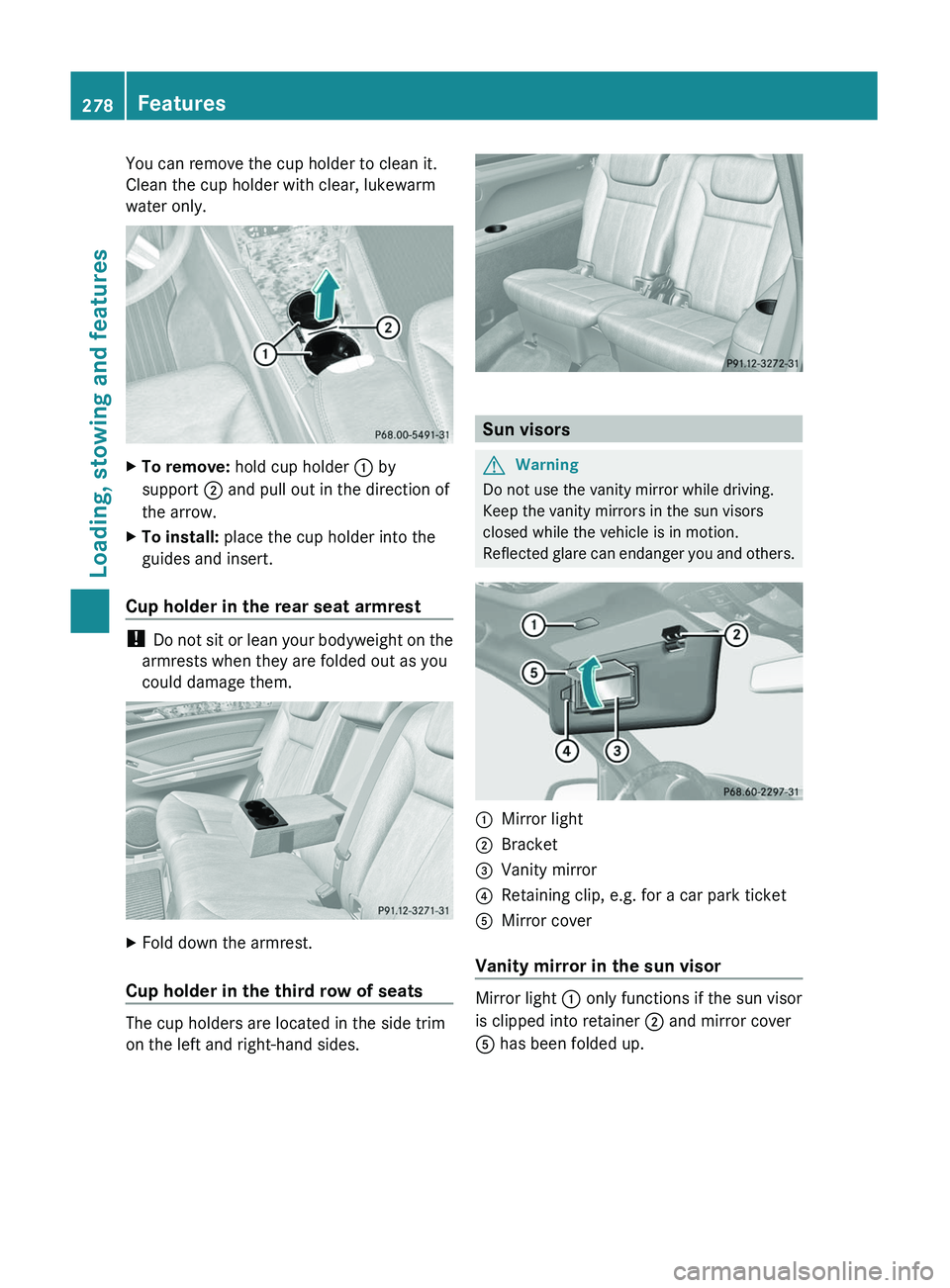
You can remove the cup holder to clean it.
Clean the cup holder with clear, lukewarm
water only.XTo remove: hold cup holder : by
support ; and pull out in the direction of
the arrow.XTo install: place the cup holder into the
guides and insert.
Cup holder in the rear seat armrest
! Do not sit or lean your bodyweight on the
armrests when they are folded out as you
could damage them.
XFold down the armrest.
Cup holder in the third row of seats
The cup holders are located in the side trim
on the left and right-hand sides.
Sun visors
GWarning
Do not use the vanity mirror while driving.
Keep the vanity mirrors in the sun visors
closed while the vehicle is in motion.
Reflected glare can endanger you and others.
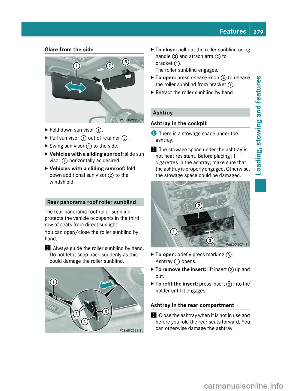
:Mirror light;Bracket=Vanity mirror?Retaining clip, e.g. for a car park ticketAMirror cover
Vanity mirror in the sun visor
Mirror light : only functions if the sun visor
is clipped into retainer ; and mirror cover
A has been folded up.
278FeaturesLoading, stowing and features
BA 164.8 USA, CA Edition B 2011; 1; 2, en-USd2sboikeVersion: 3.0.3.52010-04-21T15:08:44+02:00 - Seite 278
Page 281 of 376
Glare from the sideXFold down sun visor :.XPull sun visor : out of retainer =.XSwing sun visor : to the side.XVehicles with a sliding sunroof: slide sun
visor : horizontally as desired.XVehicles with a sliding sunroof: fold
down additional sun visor ; to the
windshield.
Rear panorama roof roller sunblind
The rear panorama roof roller sunblind
protects the vehicle occupants in the third
row of seats from direct sunlight.
You can open/close the roller sunblind by
hand.
! Always guide the roller sunblind by hand.
Do not let it snap back suddenly as this
could damage the roller sunblind.
XTo close: pull out the roller sunblind using
handle = and attach arm ; to
bracket :.
The roller sunblind engages.XTo open: press release knob ? to release
the roller sunblind from bracket :.XRetract the roller sunblind by hand.
Ashtray
Ashtray in the cockpit
i There is a stowage space under the
ashtray.
! The stowage space under the ashtray is
not heat resistant. Before placing lit
cigarettes in the ashtray, make sure that
the ashtray is properly engaged. Otherwise,
the stowage space could be damaged.
XTo open: briefly press marking =.
Ashtray : opens.XTo remove the insert: lift insert ; up and
out.XTo refit the insert: press insert ; into the
holder until it engages.
Ashtray in the rear compartment
! Close the ashtray when it is not in use and
before you fold the rear seats forward. You
can otherwise damage the ashtray.
Features279Loading, stowing and featuresBA 164.8 USA, CA Edition B 2011; 1; 2, en-USd2sboikeVersion: 3.0.3.52010-04-21T15:08:44+02:00 - Seite 279Z
Page 284 of 376
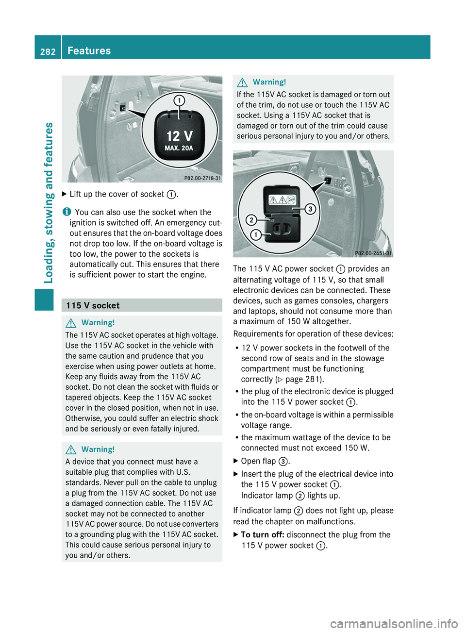
XLift up the cover of socket :.
i
You can also use the socket when the
ignition is switched off. An emergency cut-
out ensures that the on-board voltage does
not drop too low. If the on-board voltage is
too low, the power to the sockets is
automatically cut. This ensures that there
is sufficient power to start the engine.
115 V socket
GWarning!
The 115V AC socket operates at high voltage.
Use the 115V AC socket in the vehicle with
the same caution and prudence that you
exercise when using power outlets at home.
Keep any fluids away from the 115V AC
socket. Do not clean the socket with fluids or
tapered objects. Keep the 115V AC socket
cover in the closed position, when not in use.
Otherwise, you could suffer an electric shock
and be seriously or even fatally injured.
GWarning!
A device that you connect must have a
suitable plug that complies with U.S.
standards. Never pull on the cable to unplug
a plug from the 115V AC socket. Do not use
a damaged connection cable. The 115V AC
socket may not be connected to another
115V AC power source. Do not use converters
to a grounding plug with the 115V AC socket.
This could cause serious personal injury to
you and/or others.
GWarning!
If the 115V AC socket is damaged or torn out
of the trim, do not use or touch the 115V AC
socket. Using a 115V AC socket that is
damaged or torn out of the trim could cause
serious personal injury to you and/or others.
The 115 V AC power socket : provides an
alternating voltage of 115 V, so that small
electronic devices can be connected. These
devices, such as games consoles, chargers
and laptops, should not consume more than
a maximum of 150 W altogether.
Requirements for operation of these devices:
R 12 V power sockets in the footwell of the
second row of seats and in the stowage
compartment must be functioning
correctly ( Y page 281).
R the plug of the electronic device is plugged
into the 115 V power socket :.
R the on-board voltage is within a permissible
voltage range.
R the maximum wattage of the device to be
connected must not exceed 150 W.
XOpen flap =.XInsert the plug of the electrical device into
the 115 V power socket :.
Indicator lamp ; lights up.
If indicator lamp ; does not light up, please
read the chapter on malfunctions.
XTo turn off: disconnect the plug from the
115 V power socket :.282FeaturesLoading, stowing and features
BA 164.8 USA, CA Edition B 2011; 1; 2, en-USd2sboikeVersion: 3.0.3.52010-04-21T15:08:44+02:00 - Seite 282
Page 314 of 376
XVehicles without KEYLESS-GO: remove
the key from the ignition lock.
XVehicles with KEYLESS-GO: open the
driver's door.
The on-board electronics have status 0,
which is the same as the key having been
removed.
XVehicles with KEYLESS-GO: remove the
Start/Stop button from the ignition lock
(Y page 147).
XAll occupants must get out of the vehicle.
Make sure that they are not endangered as
they get out of the vehicle.
XMake sure that no one is near the danger
area whilst a wheel is being changed.
Anyone who is not directly assisting in the
wheel change should, for example, stand
behind the barrier.
XGet out of the vehicle. Pay attention to
traffic conditions when doing so.
XClose the driver's door.
iOnly operate the electric air pump using
the socket in the footwell of the 2nd row of
seats (Y page 281), even if the ignition is
turned off.
An emergency cut-off ensures that the on-
board voltage does not drop too low. If the
on-board voltage is too low, power to the
sockets is automatically cut-off. This
ensures that there is sufficient power to
start the engine.
TIREFIT kit
Using the TIREFIT kit
You can use the TIREFIT kit to seal small
punctures, particularly those in the tire tread.
You can use TIREFIT at outside temperatures
down to -4 ‡ (-20 †).
GWarning
TIREFIT is a limited repair device. TIREFIT
cannot be used for cuts or punctures larger
than approximately 0.16 in (4 mm) and tire
damage caused by driving with extremely low
tire inflation pressure, or on a flat tire, or a
damaged wheel.
Do not drive the vehicle under such
circumstances.
Contact the nearest authorized Mercedes-
Benz Center for assistance or call roadside
assistance.
XDo not remove any foreign objects which
have penetrated the tire, e.g. screws or
nails.
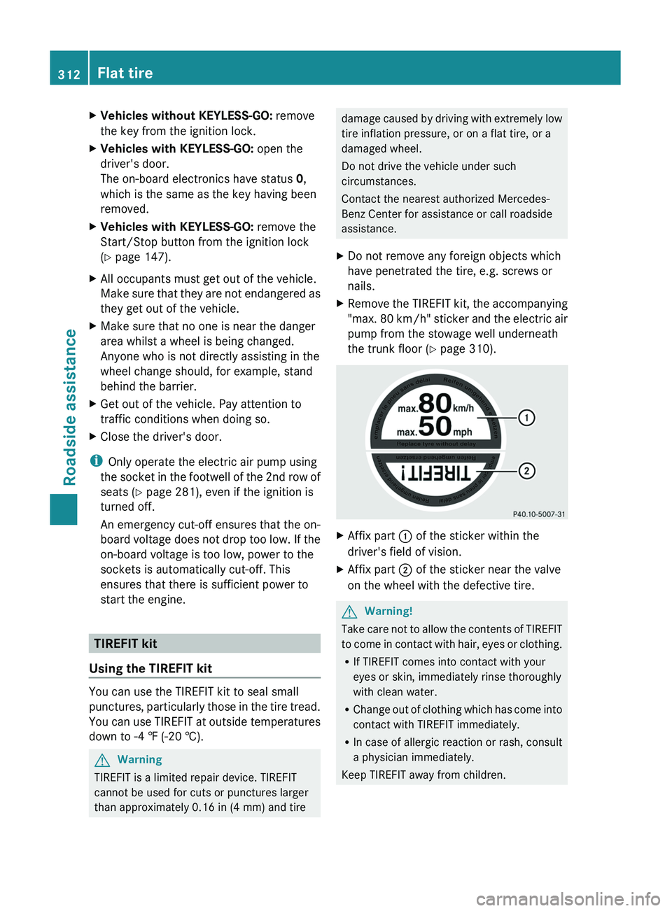
XRemove the TIREFIT kit, the accompanying
"max. 80 km/h" sticker and the electric air
pump from the stowage well underneath
the trunk floor (Y page 310).
XAffix part : of the sticker within the
driver's field of vision.
XAffix part ; of the sticker near the valve
on the wheel with the defective tire.
GWarning!
Take care not to allow the contents of TIREFIT
to come in contact with hair, eyes or clothing.
RIf TIREFIT comes into contact with your
eyes or skin, immediately rinse thoroughly
with clean water.
RChange out of clothing which has come into
contact with TIREFIT immediately.
RIn case of allergic reaction or rash, consult
a physician immediately.
Keep TIREFIT away from children.
312Flat tireRoadside assistance
BA 164.8 USA, CA Edition B 2011; 1; 2, en-USd2sboikeVersion: 3.0.3.52010-04-21T15:08:44+02:00 - Seite 312
Page 315 of 376
RIf TIREFIT is swallowed, immediately rinse
your mouth out thoroughly with water and
drink plenty of water.
RDo not induce vomiting. Consult a doctor
immediately.
RDo not inhale TIREFIT fumes.
iIf TIREFIT leaks out, allow it to dry. It can
then be removed like a layer of film.
If you get TIREFIT on your clothing, have it
cleaned as soon as possible with
perchloroethylene.
GWarning!
Comply with the manufacturer's safety
instructions on the sticker on the electric air
pump.
Your vehicle is provided with one of two
different electric air pumps:
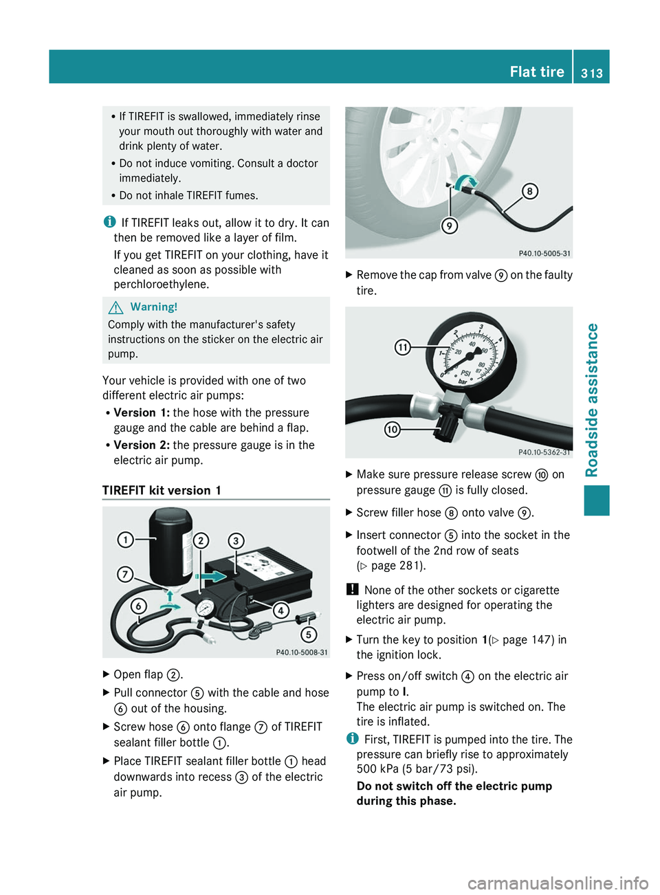
RVersion 1: the hose with the pressure
gauge and the cable are behind a flap.
RVersion 2: the pressure gauge is in the
electric air pump.
TIREFIT kit version 1
XOpen flap ;.XPull connector A with the cable and hose
B out of the housing.
XScrew hose B onto flange C of TIREFIT
sealant filler bottle :.
XPlace TIREFIT sealant filler bottle : head
downwards into recess = of the electric
air pump.
XRemove the cap from valve E on the faulty
tire.
XMake sure pressure release screw F on
pressure gauge G is fully closed.
XScrew filler hose D onto valve E.XInsert connector A into the socket in the
footwell of the 2nd row of seats
(Y page 281).
! None of the other sockets or cigarette
lighters are designed for operating the
electric air pump.
XTurn the key to position 1(Y page 147) in
the ignition lock.
XPress on/off switch ? on the electric air
pump to I.
The electric air pump is switched on. The
tire is inflated.
iFirst, TIREFIT is pumped into the tire. The
pressure can briefly rise to approximately
500 kPa (5 bar/73 psi).
Do not switch off the electric pump
during this phase.
Flat tire313Roadside assistanceBA 164.8 USA, CA Edition B 2011; 1; 2, en-USd2sboikeVersion: 3.0.3.52010-04-21T15:08:44+02:00 - Seite 313Z
Page 316 of 376
XLet the electric pump run for five minutes.
The tire should then have attained a
pressure of at least 180 kPa (1.8 bar/
26 psi).
GWarning
The air hose can become hot during inflation.
Please exercise appropriate caution.
! Do not operate the electric air pump for
longer than eight minutes at a time without
a break. It may otherwise overheat.
The air pump can be operated again once
it has cooled down.
If after five minutes a pressure of 180 kPa
(1.8 bar/26 psi) has been achieved, see
(Y page 315).
If after five minutes a pressure of 180 kPa
(1.8 bar/26 psi) has not been achieved, see
(Y page 315).
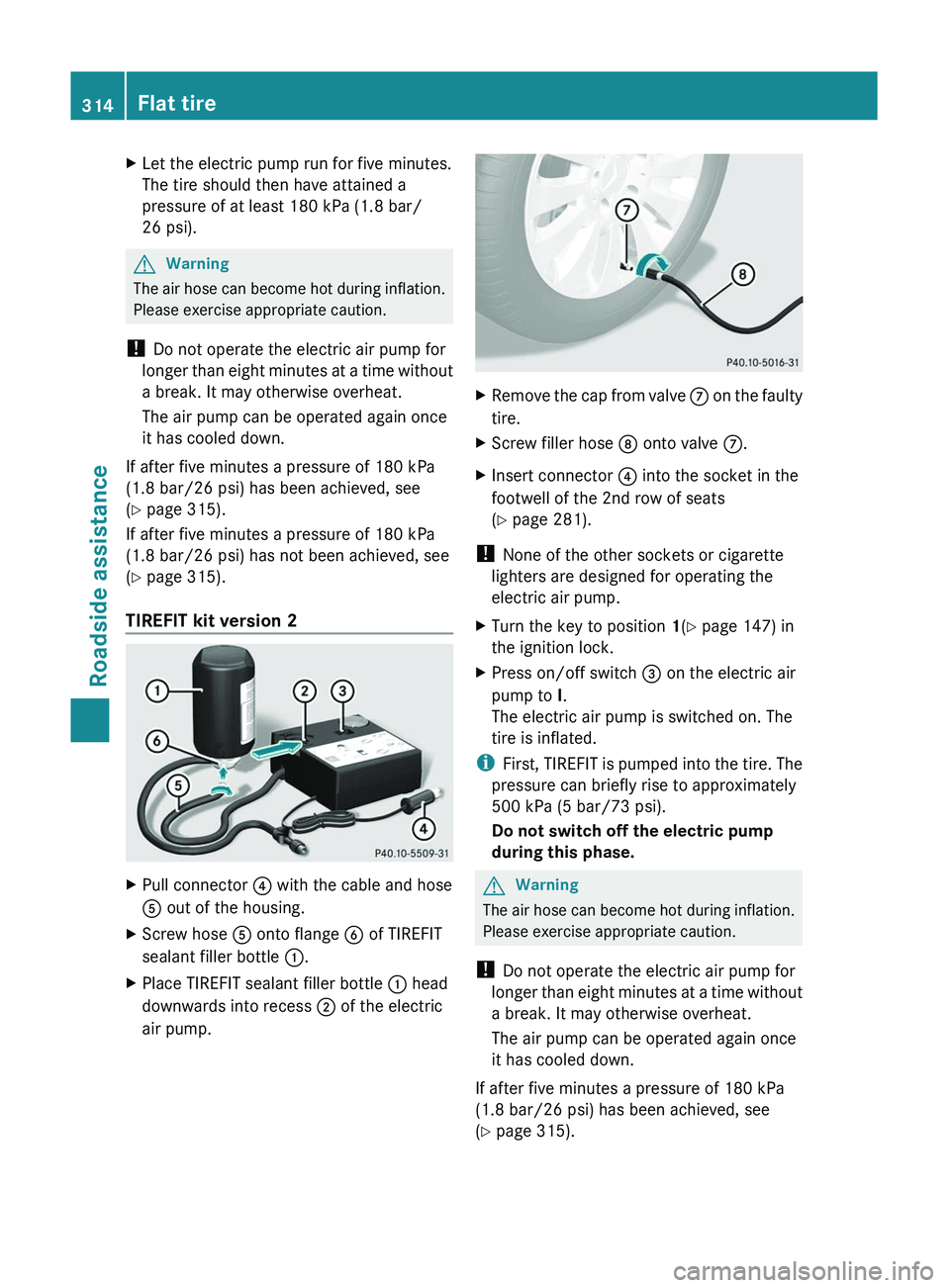
TIREFIT kit version 2
XPull connector ? with the cable and hose
A out of the housing.
XScrew hose A onto flange B of TIREFIT
sealant filler bottle :.
XPlace TIREFIT sealant filler bottle : head
downwards into recess ; of the electric
air pump.
XRemove the cap from valve C on the faulty
tire.
XScrew filler hose D onto valve C.XInsert connector ? into the socket in the
footwell of the 2nd row of seats
(Y page 281).
! None of the other sockets or cigarette
lighters are designed for operating the
electric air pump.
XTurn the key to position 1(Y page 147) in
the ignition lock.
XPress on/off switch = on the electric air
pump to I.
The electric air pump is switched on. The
tire is inflated.
iFirst, TIREFIT is pumped into the tire. The
pressure can briefly rise to approximately
500 kPa (5 bar/73 psi).
Do not switch off the electric pump
during this phase.
GWarning
The air hose can become hot during inflation.
Please exercise appropriate caution.
! Do not operate the electric air pump for
longer than eight minutes at a time without
a break. It may otherwise overheat.
The air pump can be operated again once
it has cooled down.
If after five minutes a pressure of 180 kPa
(1.8 bar/26 psi) has been achieved, see
(Y page 315).
314Flat tireRoadside assistance
BA 164.8 USA, CA Edition B 2011; 1; 2, en-USd2sboikeVersion: 3.0.3.52010-04-21T15:08:44+02:00 - Seite 314
Page 340 of 376
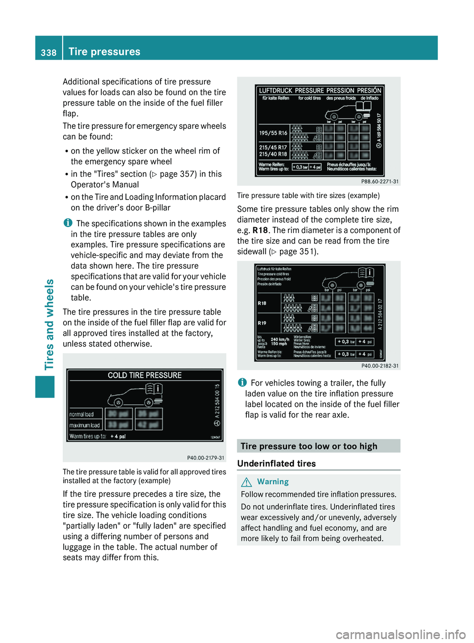
Additional specifications of tire pressure
values for loads can also be found on the tire
pressure table on the inside of the fuel filler
flap.
The tire pressure for emergency spare wheels
can be found:
R on the yellow sticker on the wheel rim of
the emergency spare wheel
R in the "Tires" section ( Y page 357) in this
Operator's Manual
R on the Tire and Loading Information placard
on the driver’s door B-pillar
i The specifications shown in the examples
in the tire pressure tables are only
examples. Tire pressure specifications are
vehicle-specific and may deviate from the
data shown here. The tire pressure
specifications that are valid for your vehicle
can be found on your vehicle's tire pressure
table.
The tire pressures in the tire pressure table
on the inside of the fuel filler flap are valid for
all approved tires installed at the factory,
unless stated otherwise.
The tire pressure table is valid for all approved tires
installed at the factory (example)
If the tire pressure precedes a tire size, the
tire pressure specification is only valid for this
tire size. The vehicle loading conditions
"partially laden" or "fully laden" are specified
using a differing number of persons and
luggage in the table. The actual number of
seats may differ from this.
Tire pressure table with tire sizes (example)
Some tire pressure tables only show the rim
diameter instead of the complete tire size,
e.g. R18 . The rim diameter is a component of
the tire size and can be read from the tire
sidewall ( Y page 351).
i
For vehicles towing a trailer, the fully
laden value on the tire inflation pressure
label located on the inside of the fuel filler
flap is valid for the rear axle.
Tire pressure too low or too high
Underinflated tires
GWarning
Follow recommended tire inflation pressures.
Do not underinflate tires. Underinflated tires
wear excessively and/or unevenly, adversely
affect handling and fuel economy, and are
more likely to fail from being overheated.
338Tire pressuresTires and wheels
BA 164.8 USA, CA Edition B 2011; 1; 2, en-USd2sboikeVersion: 3.0.3.52010-04-21T15:08:44+02:00 - Seite 338
Page 347 of 376
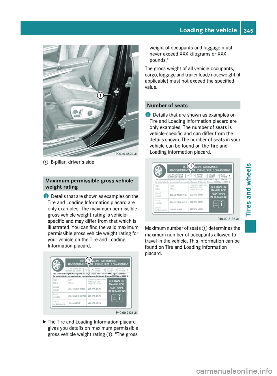
:B-pillar, driver's side
Maximum permissible gross vehicle
weight rating
i Details that are shown as examples on the
Tire and Loading Information placard are
only examples. The maximum permissible
gross vehicle weight rating is vehicle-
specific and may differ from that which is
illustrated. You can find the valid maximum
permissible gross vehicle weight rating for
your vehicle on the Tire and Loading
Information placard.
XThe Tire and Loading Information placard
gives you details on maximum permissible
gross vehicle weight rating :: "The grossweight of occupants and luggage must
never exceed XXX kilograms or XXX
pounds."
The gross weight of all vehicle occupants,
cargo, luggage and trailer load/noseweight (if
applicable) must not exceed the specified
value.
Number of seats
i Details that are shown as examples on
Tire and Loading Information placard are
only examples. The number of seats is
vehicle-specific and can differ from the
details shown. The number of seats in your
vehicle can be found on the Tire and
Loading Information placard.
Maximum number of seats : determines the
maximum number of occupants allowed to
travel in the vehicle. This information can be
found on Tire and Loading Information
placard.
Loading the vehicle345Tires and wheelsBA 164.8 USA, CA Edition B 2011; 1; 2, en-USd2sboikeVersion: 3.0.3.52010-04-21T15:08:44+02:00 - Seite 345Z