2011 MERCEDES-BENZ GL warning
[x] Cancel search: warningPage 278 of 376
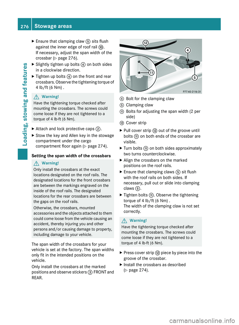
XEnsure that clamping claw A sits flush
against the inner edge of roof rail F.
If necessary, adjust the span width of the
crossbar ( Y page 276).XSlightly tighten up bolts ? on both sides
in a clockwise direction.XTighten up bolts ? on the front and rear
crossbars. Observe the tightening torque of
4 lb/ft (6 Nm) .GWarning!
Have the tightening torque checked after
mounting the crossbars. The screws could
come loose if they are not tightened to a
torque of 4 lb-ft (6 Nm).
XAttach and lock protective caps ;.XStow the key and Allen key in the stowage
compartment under the cargo
compartment floor again ( Y page 274).
Setting the span width of the crossbars
GWarning!
Only install the crossbars at the exact
locations designated on the roof rails. The
designated locations for the front crossbars
are between the markings engraved on the
inside of the roof rails. The designated
locations for the rear crossbars are between
the gaps on the roof rails.
Otherwise, the crossbars, mounted
accessories and the objects attached to them
could come loose from the vehicle causing an
accident, thereby injuring you and other
persons and/or causing damage to property,
including damage to your vehicle.
The span width of the crossbars for your
vehicle is set at the factory. The span widths
only fit in the intended positions on the
vehicle.
Only install the crossbars at the marked
positions and observe stickers = FRONT and
REAR.
?Bolt for the clamping clawAClamping clawGBolts for adjusting the span width (2 per
side)HCover stripXPull cover strip H out of the groove until
bolts G on both ends of the crossbar are
visible.XTurn bolts G on both sides approximately
two turns counterclockwise.XAlign the crossbars on the marked
positions on the roof rails.XEnsure that clamping claws A sit flush
with the roof rails on both sides. If
necessary, pull out or slide into clamping
claws A.XTighten bolts G. Observe the tightening
torque of 4 lb/ft (6 Nm) .
The width of the clamping claw is not set
correctly.GWarning!
Have the tightening torque checked after
mounting the crossbars. The screws could
come loose if they are not tightened to a
torque of 4 lb-ft (6 Nm).
XPress cover strip H piece by piece into the
groove of the crossbar.XInstall the crossbars as described
( Y page 274).276Stowage areasLoading, stowing and features
BA 164.8 USA, CA Edition B 2011; 1; 2, en-USd2sboikeVersion: 3.0.3.52010-04-21T15:08:44+02:00 - Seite 276
Page 279 of 376
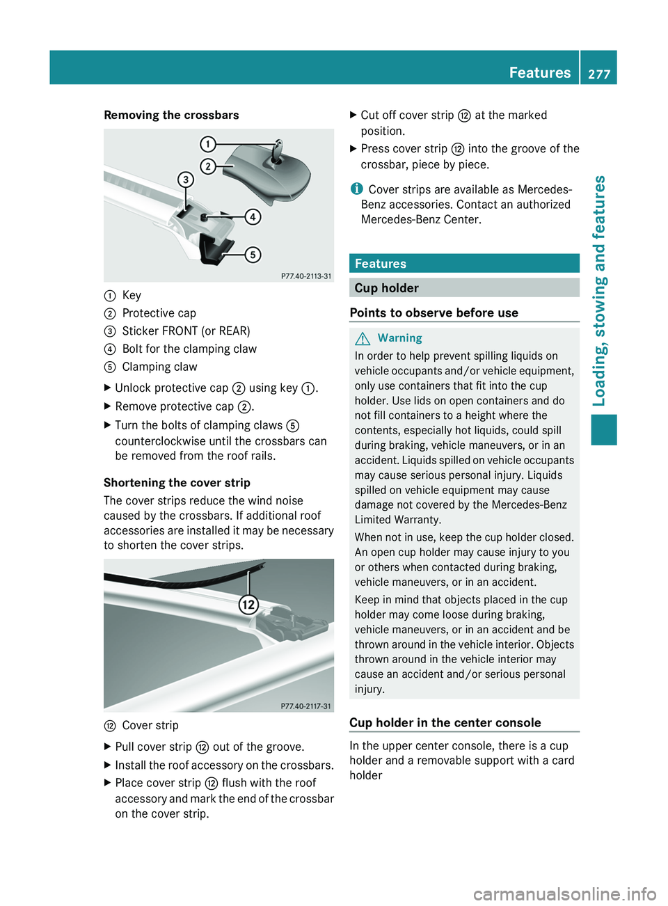
Removing the crossbars:Key;Protective cap=Sticker FRONT (or REAR)?Bolt for the clamping clawAClamping clawXUnlock protective cap ; using key :.XRemove protective cap ;.XTurn the bolts of clamping claws A
counterclockwise until the crossbars can
be removed from the roof rails.
Shortening the cover strip
The cover strips reduce the wind noise
caused by the crossbars. If additional roof
accessories are installed it may be necessary
to shorten the cover strips.
HCover stripXPull cover strip H out of the groove.XInstall the roof accessory on the crossbars.XPlace cover strip H flush with the roof
accessory and mark the end of the crossbar
on the cover strip.XCut off cover strip H at the marked
position.XPress cover strip H into the groove of the
crossbar, piece by piece.
i Cover strips are available as Mercedes-
Benz accessories. Contact an authorized
Mercedes-Benz Center.
Features
Cup holder
Points to observe before use
GWarning
In order to help prevent spilling liquids on
vehicle occupants and/or vehicle equipment,
only use containers that fit into the cup
holder. Use lids on open containers and do
not fill containers to a height where the
contents, especially hot liquids, could spill
during braking, vehicle maneuvers, or in an
accident. Liquids spilled on vehicle occupants
may cause serious personal injury. Liquids
spilled on vehicle equipment may cause
damage not covered by the Mercedes-Benz
Limited Warranty.
When not in use, keep the cup holder closed.
An open cup holder may cause injury to you
or others when contacted during braking,
vehicle maneuvers, or in an accident.
Keep in mind that objects placed in the cup
holder may come loose during braking,
vehicle maneuvers, or in an accident and be
thrown around in the vehicle interior. Objects
thrown around in the vehicle interior may
cause an accident and/or serious personal
injury.
Cup holder in the center console
In the upper center console, there is a cup
holder and a removable support with a card
holder
Features277Loading, stowing and featuresBA 164.8 USA, CA Edition B 2011; 1; 2, en-USd2sboikeVersion: 3.0.3.52010-04-21T15:08:44+02:00 - Seite 277Z
Page 280 of 376
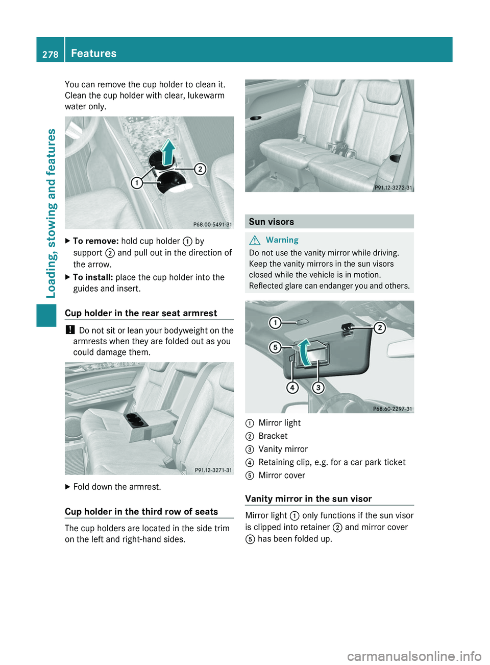
You can remove the cup holder to clean it.
Clean the cup holder with clear, lukewarm
water only.XTo remove: hold cup holder : by
support ; and pull out in the direction of
the arrow.XTo install: place the cup holder into the
guides and insert.
Cup holder in the rear seat armrest
! Do not sit or lean your bodyweight on the
armrests when they are folded out as you
could damage them.
XFold down the armrest.
Cup holder in the third row of seats
The cup holders are located in the side trim
on the left and right-hand sides.
Sun visors
GWarning
Do not use the vanity mirror while driving.
Keep the vanity mirrors in the sun visors
closed while the vehicle is in motion.
Reflected glare can endanger you and others.
:Mirror light;Bracket=Vanity mirror?Retaining clip, e.g. for a car park ticketAMirror cover
Vanity mirror in the sun visor
Mirror light : only functions if the sun visor
is clipped into retainer ; and mirror cover
A has been folded up.
278FeaturesLoading, stowing and features
BA 164.8 USA, CA Edition B 2011; 1; 2, en-USd2sboikeVersion: 3.0.3.52010-04-21T15:08:44+02:00 - Seite 278
Page 282 of 376
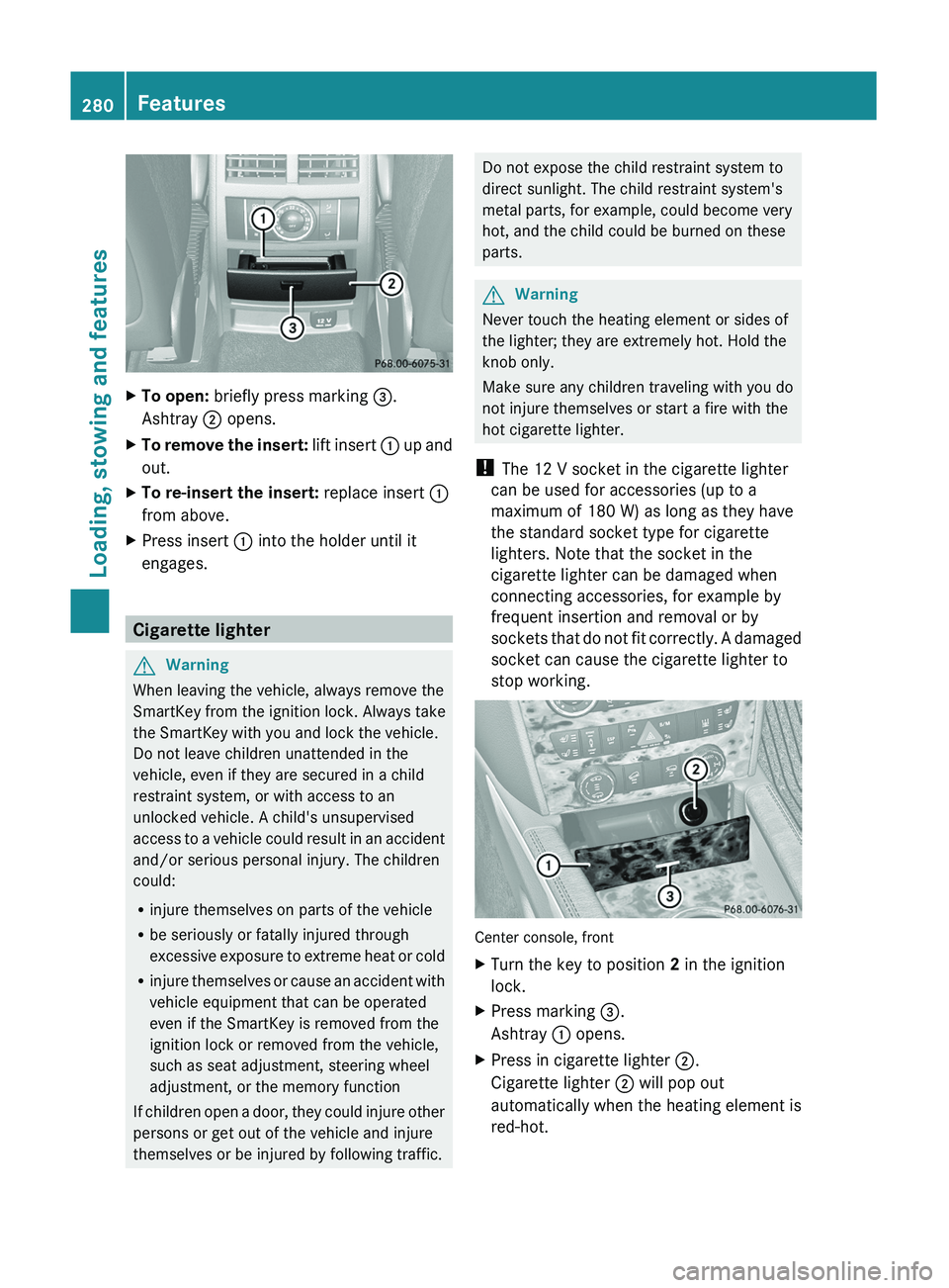
XTo open: briefly press marking =.
Ashtray ; opens.XTo remove the insert: lift insert : up and
out.XTo re-insert the insert: replace insert :
from above.XPress insert : into the holder until it
engages.
Cigarette lighter
GWarning
When leaving the vehicle, always remove the
SmartKey from the ignition lock. Always take
the SmartKey with you and lock the vehicle.
Do not leave children unattended in the
vehicle, even if they are secured in a child
restraint system, or with access to an
unlocked vehicle. A child's unsupervised
access to a vehicle could result in an accident
and/or serious personal injury. The children
could:
R injure themselves on parts of the vehicle
R be seriously or fatally injured through
excessive exposure to extreme heat or cold
R injure themselves or cause an accident with
vehicle equipment that can be operated
even if the SmartKey is removed from the
ignition lock or removed from the vehicle,
such as seat adjustment, steering wheel
adjustment, or the memory function
If children open a door, they could injure other
persons or get out of the vehicle and injure
themselves or be injured by following traffic.
Do not expose the child restraint system to
direct sunlight. The child restraint system's
metal parts, for example, could become very
hot, and the child could be burned on these
parts.GWarning
Never touch the heating element or sides of
the lighter; they are extremely hot. Hold the
knob only.
Make sure any children traveling with you do
not injure themselves or start a fire with the
hot cigarette lighter.
! The 12 V socket in the cigarette lighter
can be used for accessories (up to a
maximum of 180 W) as long as they have
the standard socket type for cigarette
lighters. Note that the socket in the
cigarette lighter can be damaged when
connecting accessories, for example by
frequent insertion and removal or by
sockets that do not fit correctly. A damaged
socket can cause the cigarette lighter to
stop working.
Center console, front
XTurn the key to position 2 in the ignition
lock.XPress marking =.
Ashtray : opens.XPress in cigarette lighter ;.
Cigarette lighter ; will pop out
automatically when the heating element is
red-hot.280FeaturesLoading, stowing and features
BA 164.8 USA, CA Edition B 2011; 1; 2, en-USd2sboikeVersion: 3.0.3.52010-04-21T15:08:44+02:00 - Seite 280
Page 284 of 376
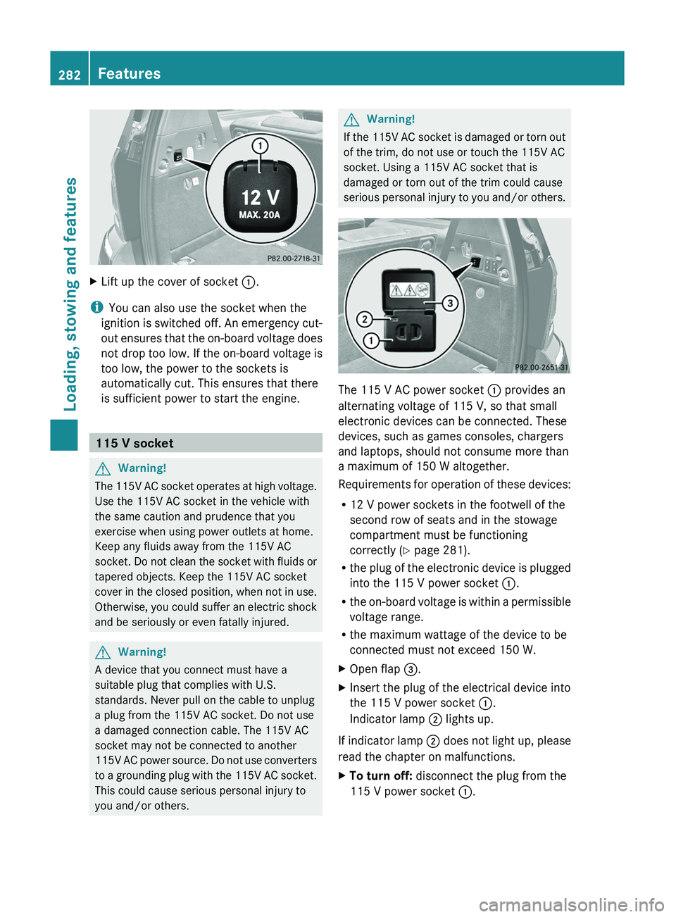
XLift up the cover of socket :.
i
You can also use the socket when the
ignition is switched off. An emergency cut-
out ensures that the on-board voltage does
not drop too low. If the on-board voltage is
too low, the power to the sockets is
automatically cut. This ensures that there
is sufficient power to start the engine.
115 V socket
GWarning!
The 115V AC socket operates at high voltage.
Use the 115V AC socket in the vehicle with
the same caution and prudence that you
exercise when using power outlets at home.
Keep any fluids away from the 115V AC
socket. Do not clean the socket with fluids or
tapered objects. Keep the 115V AC socket
cover in the closed position, when not in use.
Otherwise, you could suffer an electric shock
and be seriously or even fatally injured.
GWarning!
A device that you connect must have a
suitable plug that complies with U.S.
standards. Never pull on the cable to unplug
a plug from the 115V AC socket. Do not use
a damaged connection cable. The 115V AC
socket may not be connected to another
115V AC power source. Do not use converters
to a grounding plug with the 115V AC socket.
This could cause serious personal injury to
you and/or others.
GWarning!
If the 115V AC socket is damaged or torn out
of the trim, do not use or touch the 115V AC
socket. Using a 115V AC socket that is
damaged or torn out of the trim could cause
serious personal injury to you and/or others.
The 115 V AC power socket : provides an
alternating voltage of 115 V, so that small
electronic devices can be connected. These
devices, such as games consoles, chargers
and laptops, should not consume more than
a maximum of 150 W altogether.
Requirements for operation of these devices:
R 12 V power sockets in the footwell of the
second row of seats and in the stowage
compartment must be functioning
correctly ( Y page 281).
R the plug of the electronic device is plugged
into the 115 V power socket :.
R the on-board voltage is within a permissible
voltage range.
R the maximum wattage of the device to be
connected must not exceed 150 W.
XOpen flap =.XInsert the plug of the electrical device into
the 115 V power socket :.
Indicator lamp ; lights up.
If indicator lamp ; does not light up, please
read the chapter on malfunctions.
XTo turn off: disconnect the plug from the
115 V power socket :.282FeaturesLoading, stowing and features
BA 164.8 USA, CA Edition B 2011; 1; 2, en-USd2sboikeVersion: 3.0.3.52010-04-21T15:08:44+02:00 - Seite 282
Page 286 of 376
GWarning
A malfunction in the system has been
detected if any or all of the following
conditions occur:
R The indicator lamp in the SOS button does
not come on during the system self-test.
R The indicator lamp in Roadside Assistance
button º does not come on during the
system self-test.
R The indicator lamp in Information button
E does not come on during the system
self-test.
R The indicator lamp in the SOS button,
Roadside Assistance button º, or
Information button E remains
illuminated constantly in red after the
system self-test.
R The message Tele Aid Inoperative or
Tele Aid Not Activated appears in the
multifunction display after the system self-
test.
If a malfunction is indicated as outlined above,
the system may not operate as expected. In
case of an emergency, help will have to be
summoned by other means.
Have the system checked at the nearest
authorized Mercedes-Benz Center or contact
the following service hotlines:
R USA: Response Center under the number
866-990-9007
R Canada: Customer Service under
1-888-923-8367
Emergency call
Important safety notes
! A license agreement must exist in order
to activate the mbrace service. Make sure
that your system is activated and ready for
use, and press the E MB info call button
to register. If you cannot carry out any of
the steps mentioned, the system may not
be activated.
If you have any questions concerning
activation, please contact one of the
following service hotlines:
R USA: Response Center under
866-990-9007
R Canada: Customer Service under
1-888-923-8367
An emergency call is dialed automatically if
an air bag or Emergency Tensioning Device is
triggered.
i An automatically dialed mbrace
emergency call cannot be canceled.
An emergency call can also be dialed
manually.
Once the emergency call is in progress, the
indicator lamp in the SOS button flashes. The
Connecting Call message appears in the
multifunction display.
COMAND is muted.
Once a connection has been established, the
Call Connected message appears in the
multifunction display.
All important information on the emergency
is compiled, for example:
R current location of the vehicle (as
determined by the GPS system)
R vehicle model
R vehicle color
R vehicle identification number
A voice connection between the Response
Center and the occupants of the vehicle will
be established automatically soon after the
emergency call has been initiated. If the
vehicle occupants are able to respond, the
Response Center will attempt to obtain more
detailed information on the emergency.
i If no vehicle occupant answers, an
ambulance is immediately sent to the
vehicle.GWarning
If the indicator lamp in the SOS button is
flashing continuously and there was no voice
connection to the Response Center
284FeaturesLoading, stowing and features
BA 164.8 USA, CA Edition B 2011; 1; 2, en-USd2sboikeVersion: 3.0.3.52010-04-21T15:08:44+02:00 - Seite 284
Page 287 of 376
established, then the mbrace system could
not initiate an emergency call (e.g. the
relevant cellular phone network is not
available).
The message Call Failed appears in the
multifunction display for approximately
10 seconds.
Should this occur, assistance must be
summoned by other means.
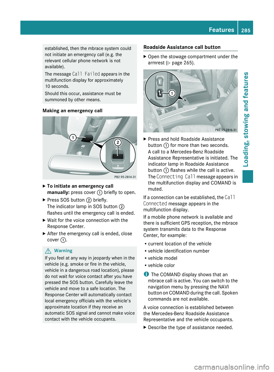
Making an emergency callXTo initiate an emergency call
manually: press cover : briefly to open.XPress SOS button ; briefly.
The indicator lamp in SOS button ;
flashes until the emergency call is ended.XWait for the voice connection with the
Response Center.XAfter the emergency call is ended, close
cover :.GWarning
If you feel at any way in jeopardy when in the
vehicle (e.g. smoke or fire in the vehicle,
vehicle in a dangerous road location), please
do not wait for voice contact after you have
pressed the SOS button. Carefully leave the
vehicle and move to a safe location. The
Response Center will automatically contact
local emergency officials with the vehicle's
approximate location if they receive an
automatic SOS signal and cannot make voice
contact with the vehicle occupants.
Roadside Assistance call buttonXOpen the stowage compartment under the
armrest ( Y page 265).XPress and hold Roadside Assistance
button : for more than two seconds.
A call to a Mercedes-Benz Roadside
Assistance Representative is initiated. The
indicator lamp in Roadside Assistance
button : flashes while the call is active.
The Connecting Call message appears in
the multifunction display and COMAND is
muted.
If a connection can be established, the Call
Connected message appears in the
multifunction display.
If a mobile phone network is available and
there is sufficient GPS reception, the mbrace
system transmits data to the Response
Center, for example:
R current location of the vehicle
R vehicle identification number
R vehicle model
R vehicle color
i The COMAND display shows that an
mbrace call is active. You can switch to the
navigation menu by pressing the NAVI
button on COMAND during the call. Spoken
commands are not available.
A voice connection is established between
the Mercedes-Benz Roadside Assistance
Representative and the vehicle occupants.
XDescribe the type of assistance needed.Features285Loading, stowing and featuresBA 164.8 USA, CA Edition B 2011; 1; 2, en-USd2sboikeVersion: 3.0.3.52010-04-21T15:08:44+02:00 - Seite 285Z
Page 290 of 376
section using your ID number and
password 40
.
i Vehicle remote unlocking is only possible
if the corresponding cellular phone
network is accessible.
The SOS button flashes and the Call
Connected message appears in the
multifunction display to confirm that the
command for vehicle remote unlocking has
been received.
If you pull the tailgate handle for more than
20 seconds before receiving authorization
for remote unlocking from the Response
Center, you must wait 15 minutes before
you can pull on the handle of the tailgate
again.
Stolen Vehicle Recovery Services
If your vehicle has been stolen:
XContact the police.
The police will issue an incident report. This
report has a number.XThis number will be forwarded to the
Response Center together with your PIN.
The Response Center will then attempt to
covertly contact the mbrace system. The
Response Center contacts you and the
local law enforcement authority if the
vehicle is located. However, only the law
enforcement authority is informed of the
location of the vehicle.
i If the anti-theft alarm system remains
activated for longer than thirty seconds,
mbrace is automatically connected to the
Customer Assistance Center.
Garage door opener
Important safety notes
Up to three different door and gate systems
can be operated using the remote control
integrated in the overhead control panel.
i Certain garage door openers are not
compatible with the integrated remote
control. If you experience difficulties with
the programming of the integrated remote
control, contact an authorized Mercedes-
Benz Center or call the following telephone
assistance service:
R USA: Mercedes-Benz Customer
Assistance Center on
1-800-FOR-MERCedes
R Canada: Customer Service
on1-800-387-0100GWarning
Before programming the integrated remote
control to a garage door opener or gate
operator, make sure people and objects are
out of the way of the device to prevent
potential harm or damage. When
programming a garage door opener, the door
moves up or down. When programming a gate
operator, the gate opens or closes.
Do not use the integrated remote control with
any garage door opener that lacks safety stop
and reverse features as required by U.S.
federal safety standards (this includes any
garage door opener model manufactured
before April 1, 1982). A garage door that
cannot detect an object - signaling the door
to stop and reverse - does not meet current
U.S. federal safety standards.
When programming a garage door opener,
park vehicle outside the garage.
Do not run the engine while programming the
integrated remote control. Inhalation of
exhaust gas is hazardous to your health. All
exhaust gas contains carbon monoxide (CO),
and inhaling it can cause unconsciousness
and possible death. All exhaust gas contains
carbon monoxide (CO), and inhaling it can
cause unconsciousness and possible death.
i USA only:
40
USA only.288FeaturesLoading, stowing and features
BA 164.8 USA, CA Edition B 2011; 1; 2, en-USd2sboikeVersion: 3.0.3.52010-04-21T15:08:44+02:00 - Seite 288