2011 MERCEDES-BENZ GL clock
[x] Cancel search: clockPage 163 of 376
XRemove the SmartKey from the ignition
lock.
KEYLESS-GO: the driver's door is open.
This returns the ignition to position 0,
which corresponds to the SmartKey being
removed. The driver's door can be closed
again.XPress the fuel filler flap in the direction of
arrow :.
The fuel filler flap opens slightly.XOpen the fuel filler flap.XTurn the fuel filler cap counter-clockwise
and remove it.XInsert the fuel filler cap into the holder
bracket on the inside of filler flap ;.XCompletely insert the filler neck of the fuel
pump nozzle into the tank and refuel.XOnly fill the tank until the pump nozzle
switches off.
! Overfilling the fuel tank could damage the
fuel system.
Closing
XReplace the fuel filler cap and turn it
clockwise. The fuel filler cap audibly
engages.
i Close the fuel filler flap before locking the
vehicle. A locking pin otherwise prevents
the fuel filler flap from closing after the
vehicle has been locked.
XClose the fuel filler flap.
Emergency fuel filler flap release
GWarning!
Avoid contact with the vehicle walls as they
may contain sharp edges. Otherwise, you
could injure yourself while releasing the fuel
filler flap.
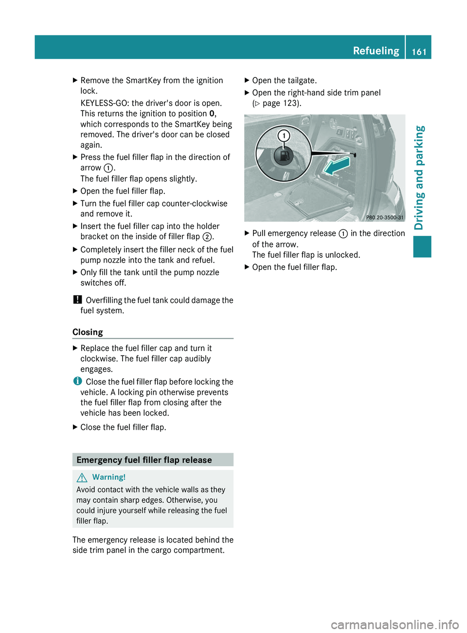
The emergency release is located behind the
side trim panel in the cargo compartment.
XOpen the tailgate.XOpen the right-hand side trim panel
( Y page 123).XPull emergency release : in the direction
of the arrow.
The fuel filler flap is unlocked.XOpen the fuel filler flap.Refueling161Driving and parkingBA 164.8 USA, CA Edition B 2011; 1; 2, en-USd2sboikeVersion: 3.0.3.52010-04-21T15:08:44+02:00 - Seite 161Z
Page 166 of 376
! AdBlue ®
is not a additive and must not be
added to the diesel tank. If AdBlue ®
is
added to the diesel tank this could damage
the engine.
i If you are adding between maintenance
intervals, add approximately 1 gallon (3.8 l)
of AdBlue ®
to the AdBlue ®
tank. 1 gallon
(3.8 l) of AdBlue ®
is approximately
2 AdBlue ®
refill bottles.
Further information about
AdBlue ®
(Y page 367).
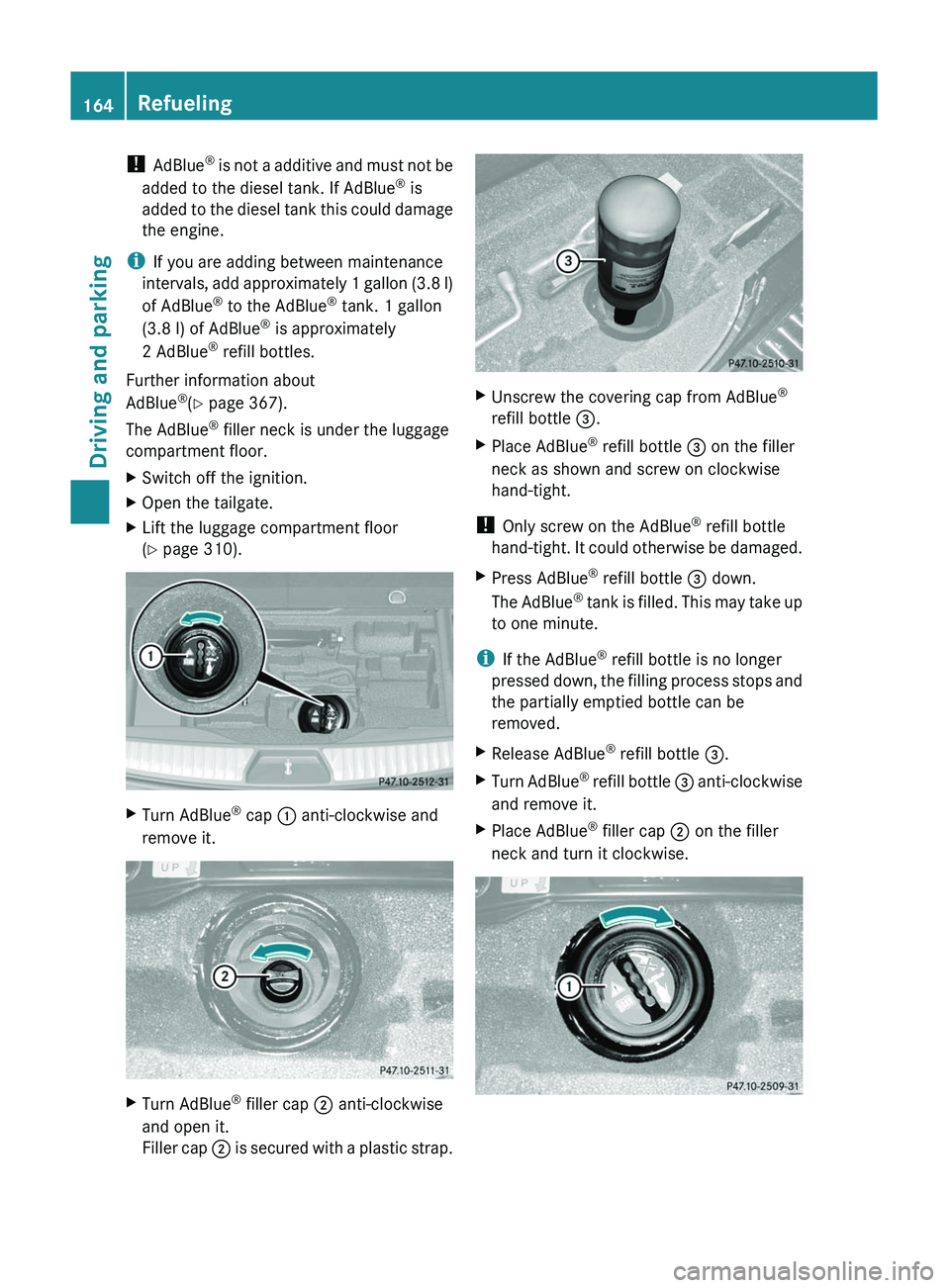
The AdBlue ®
filler neck is under the luggage
compartment floor.XSwitch off the ignition.XOpen the tailgate.XLift the luggage compartment floor
( Y page 310).XTurn AdBlue ®
cap : anti-clockwise and
remove it.XTurn AdBlue ®
filler cap ; anti-clockwise
and open it.
Filler cap ; is secured with a plastic strap.XUnscrew the covering cap from AdBlue ®
refill bottle =.XPlace AdBlue ®
refill bottle = on the filler
neck as shown and screw on clockwise
hand-tight.
! Only screw on the AdBlue ®
refill bottle
hand-tight. It could otherwise be damaged.
XPress AdBlue ®
refill bottle = down.
The AdBlue ®
tank is filled. This may take up
to one minute.
i If the AdBlue ®
refill bottle is no longer
pressed down, the filling process stops and
the partially emptied bottle can be
removed.
XRelease AdBlue ®
refill bottle =.XTurn AdBlue ®
refill bottle = anti-clockwise
and remove it.XPlace AdBlue ®
filler cap ; on the filler
neck and turn it clockwise.164RefuelingDriving and parking
BA 164.8 USA, CA Edition B 2011; 1; 2, en-USd2sboikeVersion: 3.0.3.52010-04-21T15:08:44+02:00 - Seite 164
Page 167 of 376
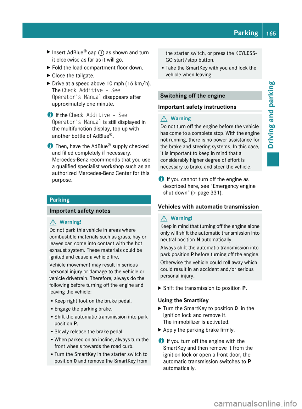
XInsert AdBlue®
cap : as shown and turn
it clockwise as far as it will go.XFold the load compartment floor down.XClose the tailgate.XDrive at a speed above 10 mph (16 km/h).
The Check Additive – See
Operator's Manual disappears after
approximately one minute.
i If the Check Additive – See
Operator's Manual is still displayed in
the multifunction display, top up with
another bottle of AdBlue ®
.
i Then, have the AdBlue ®
supply checked
and filled completely if necessary.
Mercedes-Benz recommends that you use
a qualified specialist workshop such as an
authorized Mercedes-Benz Center for this
purpose.
Parking
Important safety notes
GWarning!
Do not park this vehicle in areas where
combustible materials such as grass, hay or
leaves can come into contact with the hot
exhaust system. These materials could be
ignited and cause a vehicle fire.
Vehicle movement may result in serious
personal injury or damage to the vehicle or
vehicle drivetrain. Therefore, always do the
following before turning off the engine and
leaving the vehicle:
R Keep right foot on the brake pedal.
R Engage the parking brake.
R Shift the automatic transmission into park
position P.
R Slowly release the brake pedal.
R When parked on an incline, always turn the
front wheels towards the road curb.
R Turn the SmartKey in the starter switch to
position 0 and remove the SmartKey from
the starter switch, or press the KEYLESS-
GO start/stop button.
R Take the SmartKey with you and lock the
vehicle when leaving.
Switching off the engine
Important safety instructions
GWarning
Do not turn off the engine before the vehicle
has come to a complete stop. With the engine
not running, there is no power assistance for
the brake and steering systems. In this case,
it is important to keep in mind that a
considerably higher degree of effort is
necessary to brake and steer the vehicle.
i If you cannot turn off the engine as
described here, see "Emergency engine
shut down" ( Y page 331).
Vehicles with automatic transmission
GWarning!
Keep in mind that turning off the engine alone
only will shift the automatic transmission into
neutral position N automatically.
Always shift the automatic transmission into
park position P before turning off the engine.
Otherwise the vehicle could roll away which
could result in an accident and/or serious
personal injury.
XShift the transmission to position P.
Using the SmartKey
XTurn the SmartKey to position 0 in the
ignition lock and remove it.
The immobilizer is activated.XApply the parking brake firmly.
i If you turn off the engine with the
SmartKey and then remove it from the
ignition lock or open a front door, the
automatic transmission switches to P
automatically.
Parking165Driving and parkingBA 164.8 USA, CA Edition B 2011; 1; 2, en-USd2sboikeVersion: 3.0.3.52010-04-21T15:08:44+02:00 - Seite 165Z
Page 194 of 376
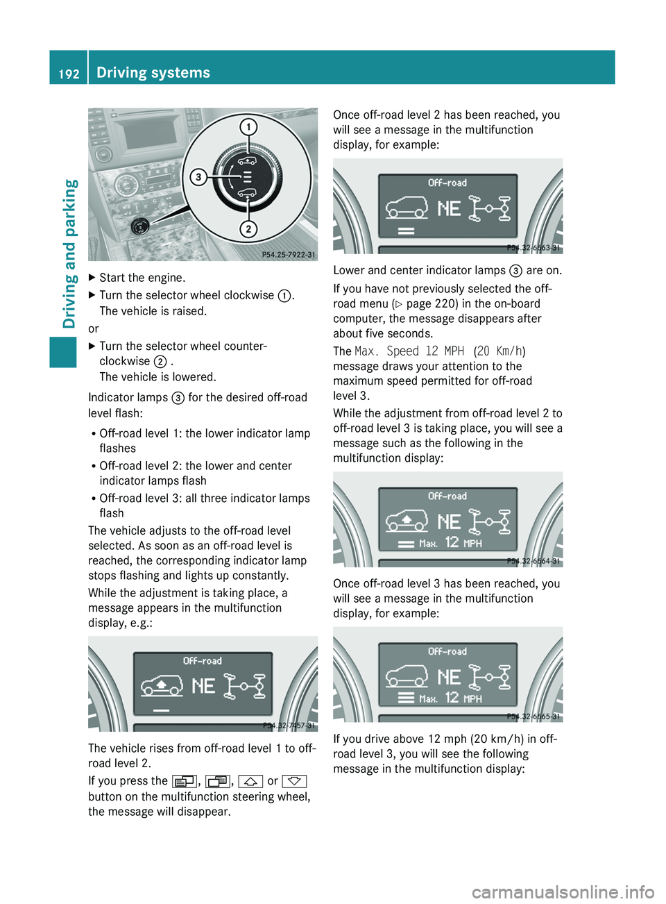
XStart the engine.XTurn the selector wheel clockwise :.
The vehicle is raised.
or
XTurn the selector wheel counter-
clockwise ; .
The vehicle is lowered.
Indicator lamps = for the desired off-road
level flash:
R Off-road level 1: the lower indicator lamp
flashes
R Off-road level 2: the lower and center
indicator lamps flash
R Off-road level 3: all three indicator lamps
flash
The vehicle adjusts to the off-road level
selected. As soon as an off-road level is
reached, the corresponding indicator lamp
stops flashing and lights up constantly.
While the adjustment is taking place, a
message appears in the multifunction
display, e.g.:
The vehicle rises from off-road level 1 to off-
road level 2.
If you press the V, U , & or *
button on the multifunction steering wheel,
the message will disappear.
Once off-road level 2 has been reached, you
will see a message in the multifunction
display, for example:
Lower and center indicator lamps = are on.
If you have not previously selected the off-
road menu ( Y page 220) in the on-board
computer, the message disappears after
about five seconds.
The Max. Speed 12 MPH (20 Km/h )
message draws your attention to the
maximum speed permitted for off-road
level 3.
While the adjustment from off-road level 2 to
off-road level 3 is taking place, you will see a
message such as the following in the
multifunction display:
Once off-road level 3 has been reached, you
will see a message in the multifunction
display, for example:
If you drive above 12 mph (20 km/h) in off-
road level 3, you will see the following
message in the multifunction display:
192Driving systemsDriving and parking
BA 164.8 USA, CA Edition B 2011; 1; 2, en-USd2sboikeVersion: 3.0.3.52010-04-21T15:08:44+02:00 - Seite 192
Page 196 of 376
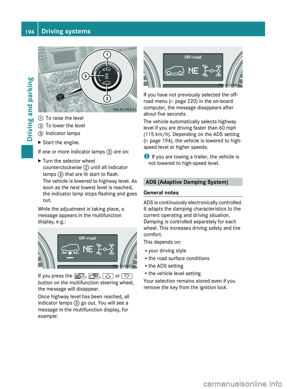
:To raise the level;To lower the level=Indicator lampsXStart the engine.
If one or more indicator lamps = are on:
XTurn the selector wheel
counterclockwise ; until all indicator
lamps = that are lit start to flash.
The vehicle is lowered to highway level. As
soon as the next lowest level is reached,
the indicator lamp stops flashing and goes
out.
While the adjustment is taking place, a
message appears in the multifunction
display, e.g.:
If you press the V, U , & or *
button on the multifunction steering wheel,
the message will disappear.
Once highway level has been reached, all
indicator lamps = go out. You will see a
message in the multifunction display, for
example:
If you have not previously selected the off-
road menu ( Y page 220) in the on-board
computer, the message disappears after
about five seconds.
The vehicle automatically selects highway
level if you are driving faster than 60 mph
(115 km/h). Depending on the ADS setting
( Y page 194), the vehicle is lowered to high-
speed level at higher speeds.
i If you are towing a trailer, the vehicle is
not lowered to high-speed level.
ADS (Adaptive Damping System)
General notes
ADS is continuously electronically controlled.
It adapts the damping characteristics to the
current operating and driving situation.
Damping is controlled separately for each
wheel. This increases driving safety and tire
comfort.
This depends on:
R your driving style
R the road surface conditions
R the ADS setting
R the vehicle level setting
Your selection remains stored even if you
remove the key from the ignition lock.
194Driving systemsDriving and parking
BA 164.8 USA, CA Edition B 2011; 1; 2, en-USd2sboikeVersion: 3.0.3.52010-04-21T15:08:44+02:00 - Seite 194
Page 224 of 376
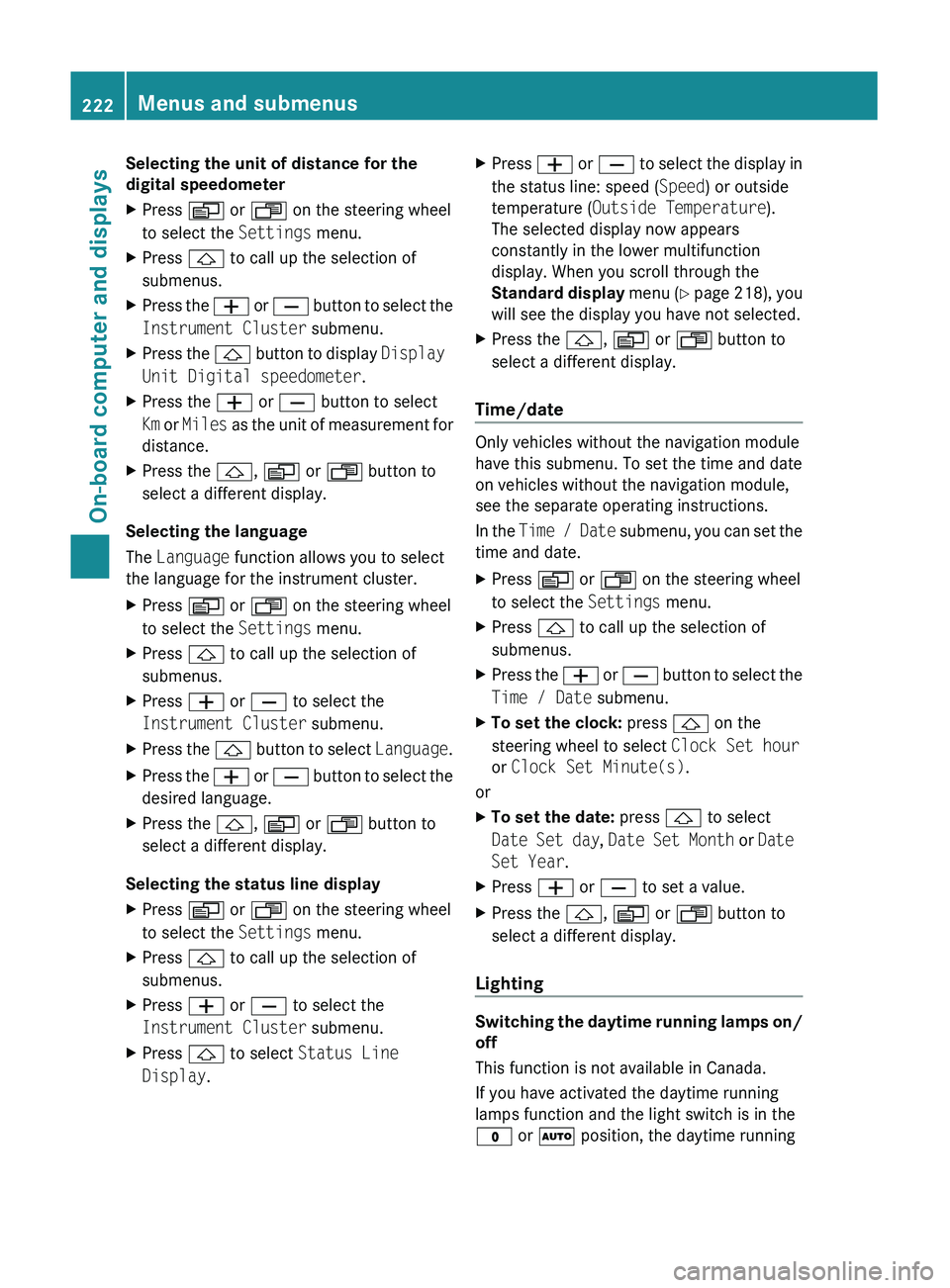
Selecting the unit of distance for the
digital speedometerXPress V or U on the steering wheel
to select the Settings menu.XPress & to call up the selection of
submenus.XPress the W or X button to select the
Instrument Cluster submenu.XPress the & button to display Display
Unit Digital speedometer .XPress the W or X button to select
Km or Miles as the unit of measurement for
distance.XPress the &, V or U button to
select a different display.
Selecting the language
The Language function allows you to select
the language for the instrument cluster.
XPress V or U on the steering wheel
to select the Settings menu.XPress & to call up the selection of
submenus.XPress W or X to select the
Instrument Cluster submenu.XPress the & button to select Language.XPress the W or X button to select the
desired language.XPress the &, V or U button to
select a different display.
Selecting the status line display
XPress V or U on the steering wheel
to select the Settings menu.XPress & to call up the selection of
submenus.XPress W or X to select the
Instrument Cluster submenu.XPress & to select Status Line
Display .XPress W or X to select the display in
the status line: speed ( Speed) or outside
temperature ( Outside Temperature ).
The selected display now appears
constantly in the lower multifunction
display. When you scroll through the
Standard display menu (Y page 218), you
will see the display you have not selected.XPress the &, V or U button to
select a different display.
Time/date
Only vehicles without the navigation module
have this submenu. To set the time and date
on vehicles without the navigation module,
see the separate operating instructions.
In the Time / Date submenu, you can set the
time and date.
XPress V or U on the steering wheel
to select the Settings menu.XPress & to call up the selection of
submenus.XPress the W or X button to select the
Time / Date submenu.XTo set the clock: press & on the
steering wheel to select Clock Set hour
or Clock Set Minute(s) .
or
XTo set the date: press & to select
Date Set day , Date Set Month or Date
Set Year .XPress W or X to set a value.XPress the &, V or U button to
select a different display.
Lighting
Switching the daytime running lamps on/
off
This function is not available in Canada.
If you have activated the daytime running
lamps function and the light switch is in the
$ or à position, the daytime running
222Menus and submenusOn-board computer and displays
BA 164.8 USA, CA Edition B 2011; 1; 2, en-USd2sboikeVersion: 3.0.3.52010-04-21T15:08:44+02:00 - Seite 222
Page 277 of 376
accessories and/or the objects attached to
them could come loose from the vehicle,
thereby injuring you and other persons and/
or causing damage to property, including
damage to your vehicle.
! Have a second person assist you when
installing the crossbars. Otherwise, the
vehicle could be damaged.
! Objects that are attached to crossbar
system accessories must not limit or
obstruct the movement of the sliding
sunroof. Otherwise, the tilt/sliding sunroof
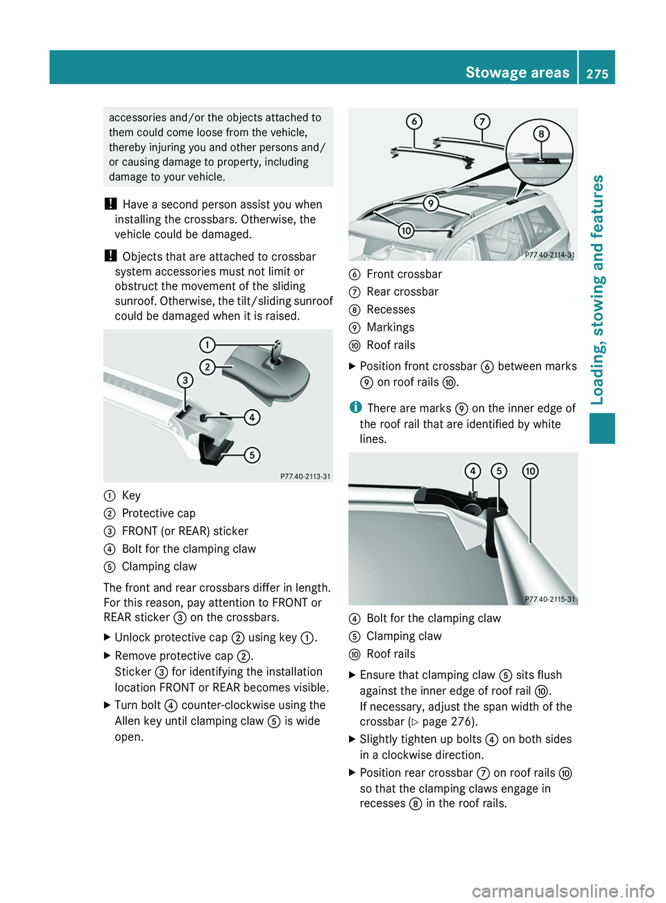
could be damaged when it is raised.:Key;Protective cap=FRONT (or REAR) sticker?Bolt for the clamping clawAClamping claw
The front and rear crossbars differ in length.
For this reason, pay attention to FRONT or
REAR sticker = on the crossbars.
XUnlock protective cap ; using key :.XRemove protective cap ;.
Sticker = for identifying the installation
location FRONT or REAR becomes visible.XTurn bolt ? counter-clockwise using the
Allen key until clamping claw A is wide
open.BFront crossbarCRear crossbarDRecessesEMarkingsFRoof railsXPosition front crossbar B between marks
E on roof rails F.
i
There are marks E on the inner edge of
the roof rail that are identified by white
lines.
?Bolt for the clamping clawAClamping clawFRoof railsXEnsure that clamping claw A sits flush
against the inner edge of roof rail F.
If necessary, adjust the span width of the
crossbar ( Y page 276).XSlightly tighten up bolts ? on both sides
in a clockwise direction.XPosition rear crossbar C on roof rails F
so that the clamping claws engage in
recesses D in the roof rails.Stowage areas275Loading, stowing and featuresBA 164.8 USA, CA Edition B 2011; 1; 2, en-USd2sboikeVersion: 3.0.3.52010-04-21T15:08:44+02:00 - Seite 275Z
Page 278 of 376
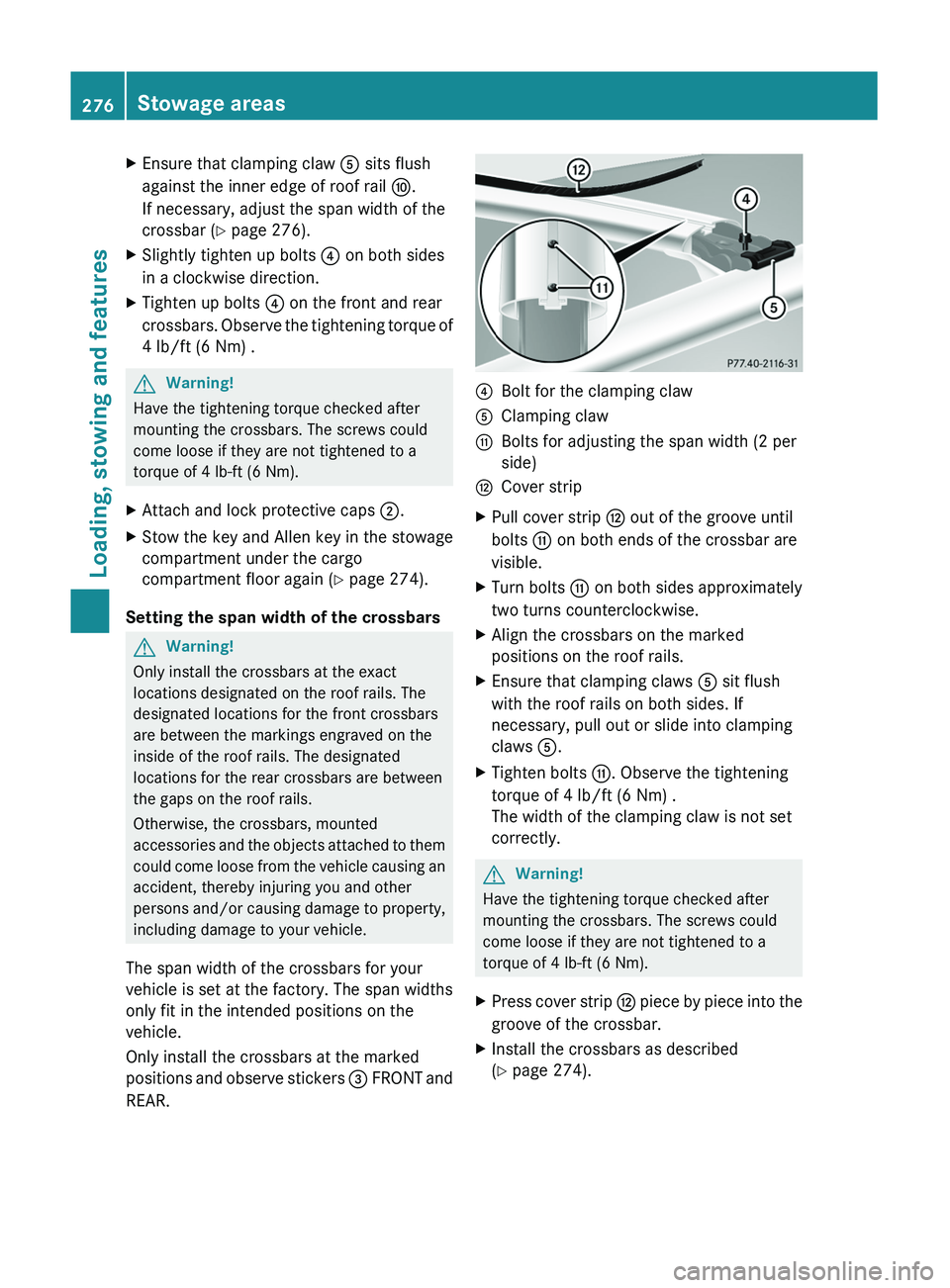
XEnsure that clamping claw A sits flush
against the inner edge of roof rail F.
If necessary, adjust the span width of the
crossbar ( Y page 276).XSlightly tighten up bolts ? on both sides
in a clockwise direction.XTighten up bolts ? on the front and rear
crossbars. Observe the tightening torque of
4 lb/ft (6 Nm) .GWarning!
Have the tightening torque checked after
mounting the crossbars. The screws could
come loose if they are not tightened to a
torque of 4 lb-ft (6 Nm).
XAttach and lock protective caps ;.XStow the key and Allen key in the stowage
compartment under the cargo
compartment floor again ( Y page 274).
Setting the span width of the crossbars
GWarning!
Only install the crossbars at the exact
locations designated on the roof rails. The
designated locations for the front crossbars
are between the markings engraved on the
inside of the roof rails. The designated
locations for the rear crossbars are between
the gaps on the roof rails.
Otherwise, the crossbars, mounted
accessories and the objects attached to them
could come loose from the vehicle causing an
accident, thereby injuring you and other
persons and/or causing damage to property,
including damage to your vehicle.
The span width of the crossbars for your
vehicle is set at the factory. The span widths
only fit in the intended positions on the
vehicle.
Only install the crossbars at the marked
positions and observe stickers = FRONT and
REAR.
?Bolt for the clamping clawAClamping clawGBolts for adjusting the span width (2 per
side)HCover stripXPull cover strip H out of the groove until
bolts G on both ends of the crossbar are
visible.XTurn bolts G on both sides approximately
two turns counterclockwise.XAlign the crossbars on the marked
positions on the roof rails.XEnsure that clamping claws A sit flush
with the roof rails on both sides. If
necessary, pull out or slide into clamping
claws A.XTighten bolts G. Observe the tightening
torque of 4 lb/ft (6 Nm) .
The width of the clamping claw is not set
correctly.GWarning!
Have the tightening torque checked after
mounting the crossbars. The screws could
come loose if they are not tightened to a
torque of 4 lb-ft (6 Nm).
XPress cover strip H piece by piece into the
groove of the crossbar.XInstall the crossbars as described
( Y page 274).276Stowage areasLoading, stowing and features
BA 164.8 USA, CA Edition B 2011; 1; 2, en-USd2sboikeVersion: 3.0.3.52010-04-21T15:08:44+02:00 - Seite 276