2011 MERCEDES-BENZ E-CLASS ESTATE remove seats
[x] Cancel search: remove seatsPage 65 of 409
R
is routed as low as possible across the pel-
vic area, in front of the hips
R is tightened across the lap by pulling
upwards on the shoulder section of the seat
belt
R is tigh tand is routed across the centre of
the child's shoulder
R is not twisted and does not pass across the
child's neck or under the child's arm
X Adjust the head restraint if necessary; see
(Y page 108).
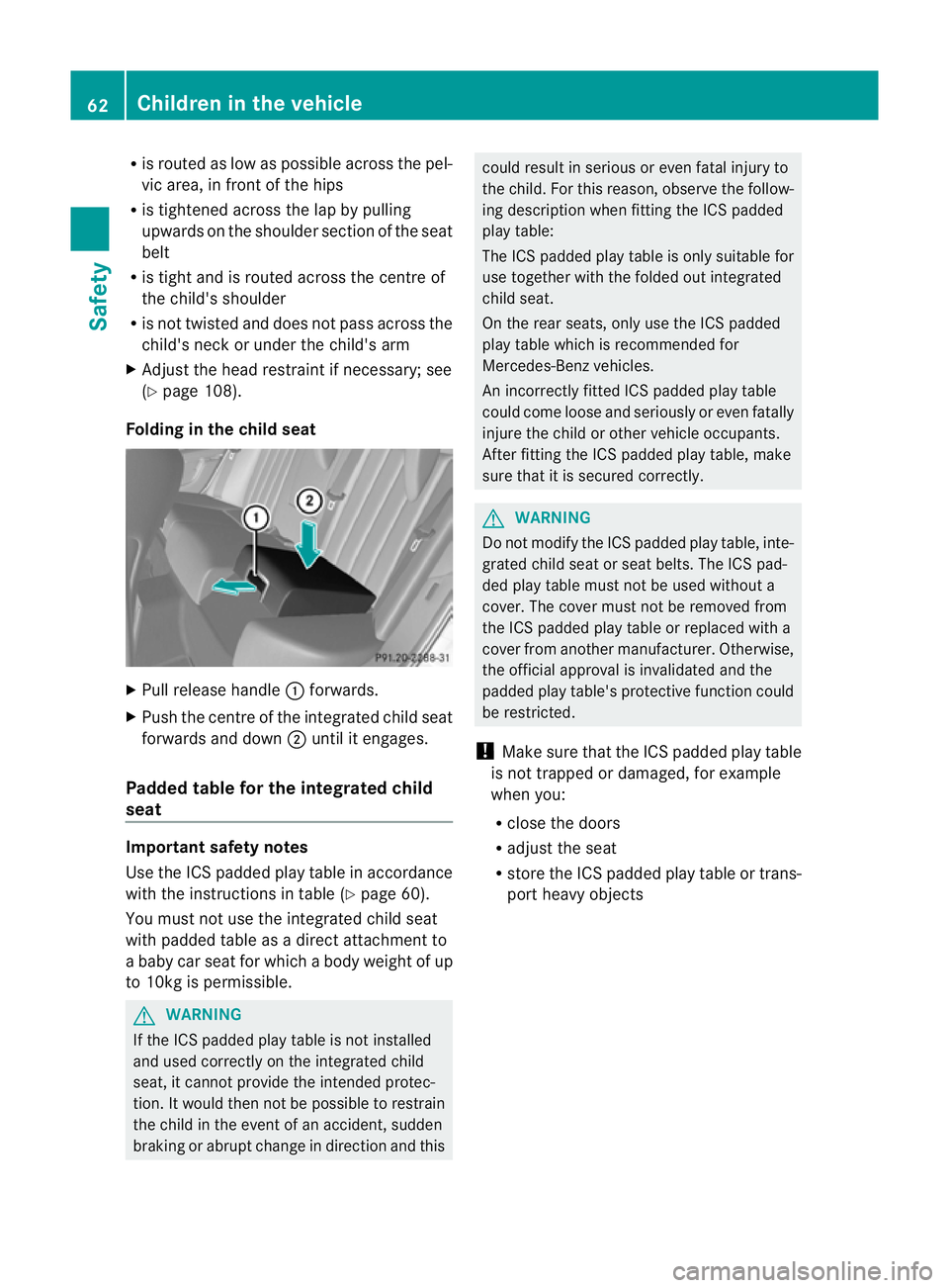
Folding in the chil dseat X
Pull release handle :forwards.
X Push the centre of the integrated child seat
forwards and down ;until it engages.
Padded table for the integrated child
seat Important safety notes
Use the ICS padded play table in accordance
with the instructions in table (Y page 60).
You must not use the integrated child seat
with padded table as a direc tattachment to
a baby car seat for which a body weight of up
to 10kg is permissible. G
WARNING
If the IC Spadded play table is no tinstalled
and used correctly on the integrated child
seat, it canno tprovide the intended protec-
tion. It would then not be possible to restrain
the child in the event of an accident, sudden
braking or abrupt change in directio nand this could resul
tinserious or even fatal injury to
the child. For this reason, observe the follow-
ing description when fitting the ICS padded
play table:
The ICS padded play table is only suitable for
use together with the folded out integrated
child seat.
On the rear seats, only use the ICS padded
play table which is recommended for
Mercedes-Benz vehicles.
An incorrectly fitted ICS padded play table
could come loose and seriously or even fatally
injure the child or other vehicle occupants.
After fitting the ICS padded play table, make
sure that it is secured correctly. G
WARNING
Do not modify the ICS padded play table, inte-
grated child seat or seat belts. The ICS pad-
ded play table must not be used without a
cover. The cover must not be removed from
the ICS padded play table or replaced with a
cover from another manufacturer. Otherwise,
the official approval is invalidated and the
padded play table's protective function could
be restricted.
! Make sure that the ICS padded play table
is not trapped or damaged, for example
when you:
R close the doors
R adjust the seat
R store the ICS padded play table or trans-
port heavy objects 62
Children in the vehicleSafety
Page 109 of 409
rials, e.g. blankets, coats, bags, seat cov-
ers, child seats or booster seats.
! Make sure that there are no objects in the
footwell or behind the seats when moving
the seat back. There is a risk that the seats
and/or the objects could be damaged.
i The head restraints in the front seats are
fitted with the NECK-PRO system
(Y page 49). For this reason, it is not pos-
sible to remove the head restraints from
the front seats.
Vehicles without the through-loading fea-
ture: the head restraints cannot be
removed from the rear compartment seats.
For more information, contact a qualified
specialist workshop.
i Further related subjects:
R Through-loading feature in the rear
bench seat (Saloon)
R EASY-PACK through-loading feature in
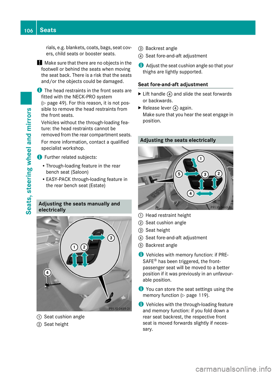
the rear bench seat (Estate) Adjusting the seats manually and
electrically :
Seat cushion angle
; Seat height =
Backrest angle
? Seat fore-and-aft adjustment
i Adjust the seat cushion angle so that your
thighs are lightly supported.
Seat fore-and-aft adjustment X
Lift handle ?and slide the seat forwards
or backwards.
X Release lever ?again.
Make sure that you heart he seat engage in
position. Adjusting the seats electrically
:
Head restraint height
; Seat cushion angle
= Seat height
? Seat fore-and-aft adjustment
A Backrest angle
i Vehicles with memory function: if PRE-
SAFE ®
has been triggered, the front-
passenger seat will be moved to a better
position if it was previously in an unfavour-
able position.
i You can store the seat settings using the
memory function (Y page 119).
i Vehicles with the through-loading feature
and memory function: if you fold down a
rear seat backrest, the respective front
seat is moved forwards slightly if neces-
sary. 106
SeatsSeats, steering wheel and mirrors
Page 112 of 409
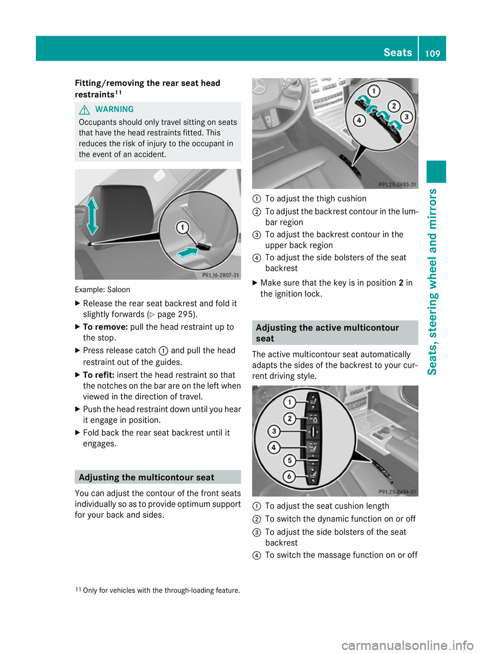
Fitting/removing the rea
rseat head
restraints 11 G
WARNING
Occupants should only travel sitting on seats
that have the head restraints fitted .This
reduces the risk of injury to the occupant in
the event of an accident. Example: Saloon
X
Release the rear seat backrest and fold it
slightly forwards (Y page 295).
X To remove: pull the head restraint up to
the stop.
X Press release catch :and pull the head
restraint out of the guides.
X To refit: insert the head restraint so that
the notches on the bar are on the left when
viewed in the direction of travel.
X Push the head restraint down until you hear
it engage in position.
X Fold back the rear seat backrest until it
engages. Adjusting the multicontour seat
You can adjust the contour of the front seats
individually so as to provide optimum support
for your back and sides. :
To adjust the thigh cushion
; To adjust the backrest contour in the lum-
bar region
= To adjust the backrest contour in the
upper back region
? To adjust the side bolsters of the seat
backrest
X Make sure that the key is in position 2in
the ignition lock. Adjusting the active multicontour
seat
The active multicontour seat automatically
adapts the sides of the backrest to your cur-
rent driving style. :
To adjust the seat cushion length
; To switch the dynamic function on or off
= To adjust the side bolsters of the seat
backrest
? To switch the massage function on or off
11 Only for vehicles with the through-loading feature. Seats
109Seats, steering wheel and mirrors Z
Page 115 of 409
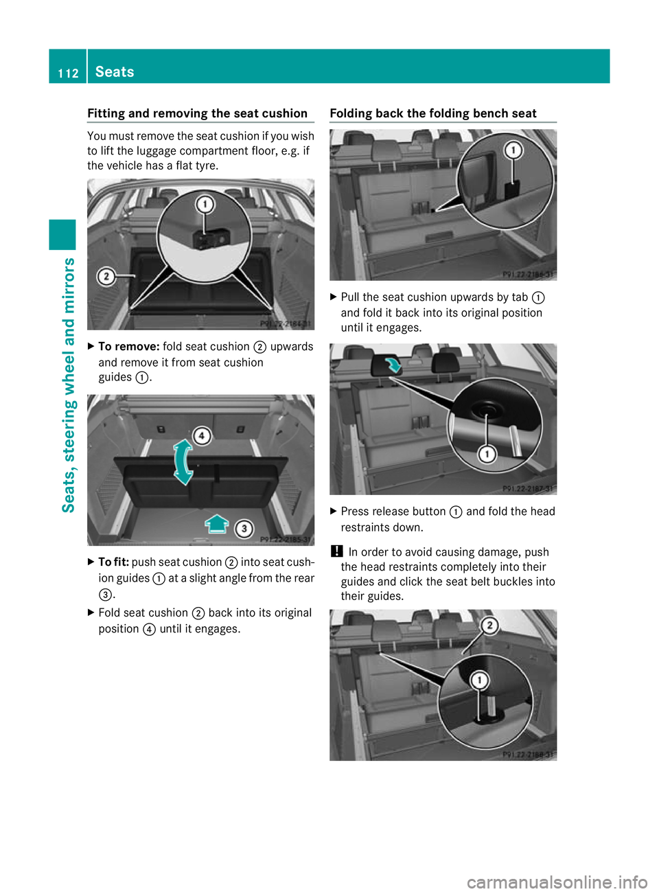
Fitting and removing the seat cushion
You must remove the seat cushion if you wish
to lift the luggage compartmen tfloor, e.g. if
the vehicle has a flat tyre. X
To remove: fold seat cushion ;upwards
and remove it fro mseat cushion
guides :. X
To fit: push seat cushion ;into seat cush-
ion guides :at a slight angle from the rear
=.
X Fold seat cushion ;back into its original
position ?until it engages. Folding back the folding bench seat X
Pull the seat cushion upwards by tab :
and fold it back into its original position
until it engages. X
Press release button :and fold the head
restraints down.
! In order to avoid causing damage, push
the head restraints completely into their
guides and click the seat belt buckles into
their guides. 112
SeatsSeats, steering wheel and mirrors
Page 119 of 409
You can activate and deactivate the EASY-
ENTRY/EXIT feature in the on-board com-
puter (Y
page 248). G
WARNING
Make sure that nobody can become trapped
when you activate the EASY-ENTRY/EXIT fea-
ture.
If there is a risk of someone becoming trap-
ped, stop the adjustmen tprocedure. To halt
the procedure:
R move the switch for steering wheel adjust-
ment in the opposite direction to that in
which the steering wheel is moving.
R press one of the memory function position
buttons.
Never leave children unsupervised in the vehi-
cle. They could open the driver's door and
thereby unintentionally activate the EASY-
ENTRY/EXIT feature and become trapped.
Position of the steering wheel when the
EASY-ENTRY/EXI Tfeatur eis active The steering wheel tilts upwards if you:
R
remove the key from the ignition lock
R open the driver's door and KEYLESS-GO is
in position 1
R open the driver's door and the key is in
position 0or 1in the ignition lock
i The steering wheel only moves upwards if
it has not already reached the upper end
stop.
If you insert the key into the ignition lock with
the driver's door closed, the steering wheel is
automatically moved to the previously set
position.
Position of the steering wheel for driv-
ing The steering wheel is moved to the previously
set position if:
R
the driver's door is closed
R you insert the key into the ignition lock or
R you press the Start/Stop button once on
vehicles with KEYLESS-GO.
If you close the driver's door with the key
inserted into the ignition lock, the steering
wheel is automatically moved to the previ-
ously set position.
The last position of the steering wheel is
stored after each manual setting or when you
store the setting with the memory function
(Y page 119).
Crash-responsive EASY-EXIT feature If the crash-responsive EASY-EXIT feature is
triggered in an accident, the steering column
will move upwards when the driver's door is
opened. This occurs irrespective of the posi-
tion of the key in the ignition lock. This makes
it easier to exit the vehicle and rescue the
occupants.
The crash-responsive EASY-EXIT feature is
only operational if the EASY-EXIT/ENTRY fea-
ture is activated in the on-board computer. Mirrors
Rear-view mirror
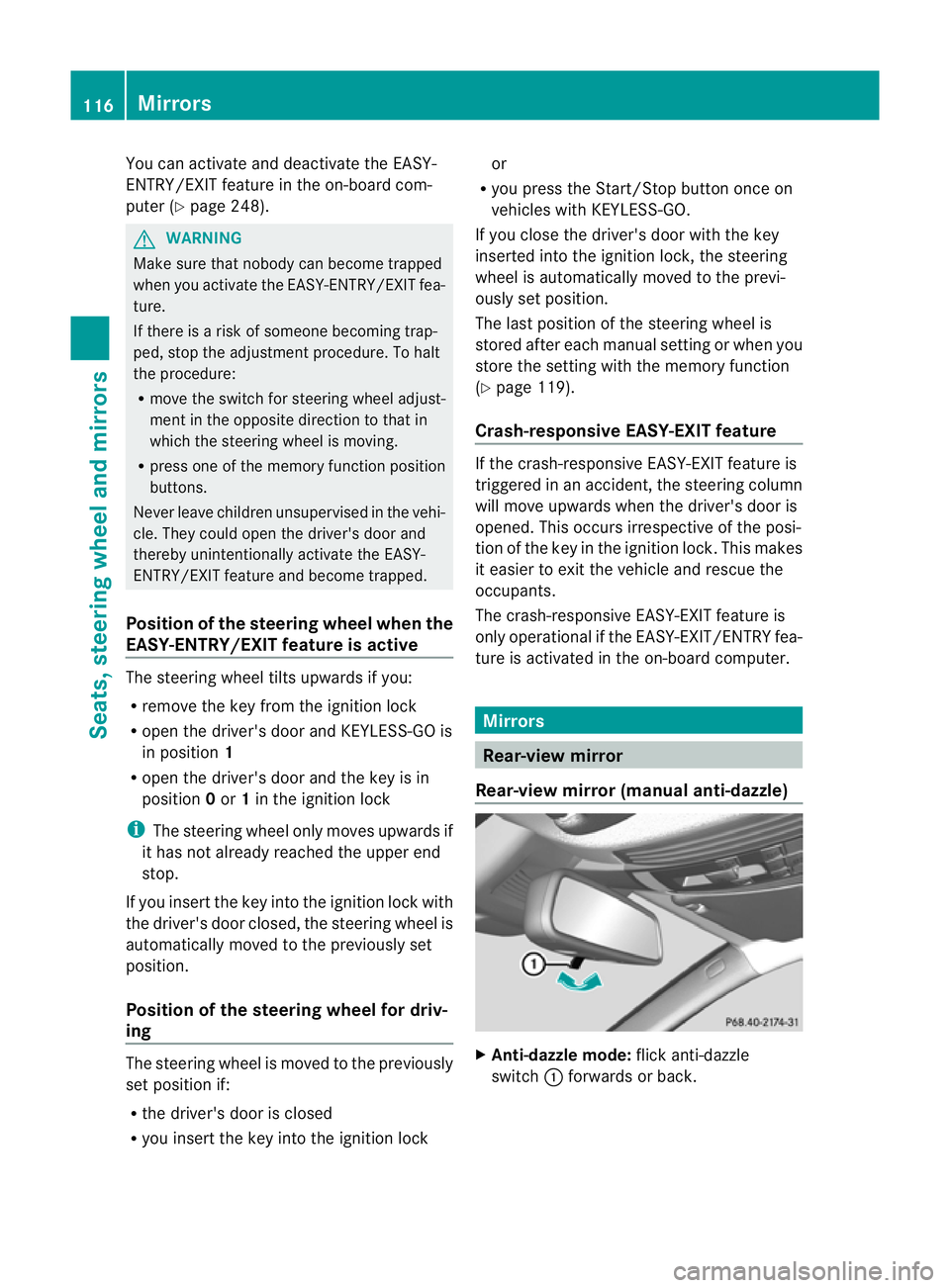
Rear-view mirror (manual anti-dazzle) X
Anti-dazzle mode: flick anti-dazzle
switch :forwards or back. 116
MirrorsSeats, steering wheel and mirrors
Page 122 of 409
and the kerb in the exterior mirror on
the front-passenger side.
X Press memory button M? and one of
the arrows on adjustment button =
within three seconds.
The parking positio nis stored if the
exterior mirror does not move.
If the mirror moves out of position, repeat
the steps.
Calling up astore dparking position set-
ting X
Tur nthe key to position 2in the ignition
lock.
X Adjust the exterior mirror on the front-
passenger side with the corresponding but-
ton (Y page 117).
X Engage reverse gear.
The exterior mirror on the front-passenger
side moves to the stored parking position.
The exterior mirror on the front-passenger
side moves back to its original position:
R as soon as you exceed a speed of
10 km/h
R about ten seconds after you have disen-
gaged reverse gear
R if you press button :for the exterior mir-
ror on the driver's side Memory function
Storing settings
G
WARNING
The memory function can still be used when
the key has been removed. For this reason,
children should never be left unsupervised in
the vehicle. They could otherwise become
trapped when adjusting the seat or the steer-
ing wheel. G
WARNING
Only use the memory function on the driver's
side when the vehicle is stationary. You could otherwise be distracted from the traffic con-
ditions by the steering wheel and seat moving
of their own accord, and as a result, cause an
accident.
With the memory function, you can store up
to three different settings, e.g. for three dif-
ferent people.
The following settings are stored as a single
memory preset:
R position of the seat, backrest and head
restraint
R active multicontour seat: dynamic function
level
R driver's side: steering wheel position
R driver's side: position of the exterior mir-
rors on the driver's and front-passenger
sides X
Adjust the seat (Y page 106).
X On the driver's side, adjust the steering
wheel (Y page 115) and the exterior mirrors
(Y page 117).
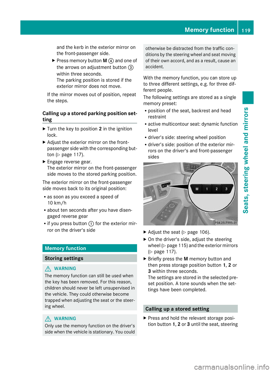
X Briefly press the Mmemory button and
then press storage position button 1,2or
3 within three seconds.
The settings are stored in the selected pre-
set position. Atone sounds when the set-
tings have been completed. Calling up
astore dsetting
X Press and hold the relevant storage posi-
tio nb utton 1,2or 3until the seat, steering Memory function
119Seats, steering wheel and mirrors Z
Page 300 of 409
G
WARNING
Always drive with the tailgate closed .Exhaust
fumes could otherwise enter the vehicle inte-
rior.
Folding the rear seat backrest forward The left-hand and right-hand rea
rseat backr-
ests can be folded forwards separately to
increase the luggage compartment capacity.
The combined luggage cover and net can
remain installed.
! Before you fold down the rear seat back-
rest, remove the side head restraints for
the integrated child seat; see the "Side
head restraints for integrated child seat"
section. The side head restraints could oth-
erwise be damaged.
! When folding the rear seat backrest for-
wards, ensure that there are no items lying
on the seat cushions .These items could
otherwise be damaged or could themselves
damage the rear seats.
i When you fold one or both parts of the
rear seat backrests forwards, the headr-
ests are also lowered if necessary. In the
case of vehicles with memory function, the
respective front seat is moved forwards
slightly to avoid contact with the seat
behind it. X
Vehicles without memory function: if nec-
essary, move the driver's or front-
passenger seat forwards.
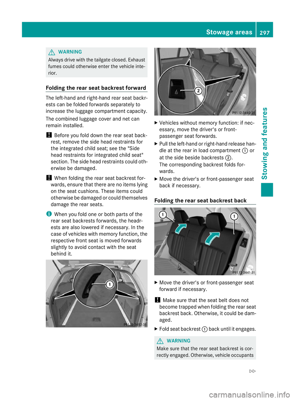
X Pull the left-hand or right-hand release han-
dle at the rear in load compartment :or
at the side beside backrests ;.
The corresponding backrest folds for-
wards.
X Move the driver's or front-passenger seat
back if necessary.
Folding the rear seat backrest back X
Move the driver's or front-passenger seat
forward if necessary.
! Make sure that the seat belt does not
become trapped when folding the rear seat
backrest back. Otherwise, it could be dam-
aged.
X Fold seat backrest :back until it engages. G
WARNING
Make sure that the rear seat backrest is cor-
rectly engaged. Otherwise, vehicle occupants Stowage areas
297Stowing and features
Z
Page 307 of 409
Otherwise, vehicle occupants could be
injured by objects being thrown around if you:
R
brake sharply
R change direction suddenly
R are involved in an accident
Please observe the loading guidelines.
Luggage holder The luggage holder can be used to secure
light loads against the side wall of the luggage
compartment to prevent them from moving
around.
!
Only use the luggage holder to secure
loads with a maximum weight of 7kg and
with dimensions that allow the loads to be
safely and securely retained by the luggage
holder. X
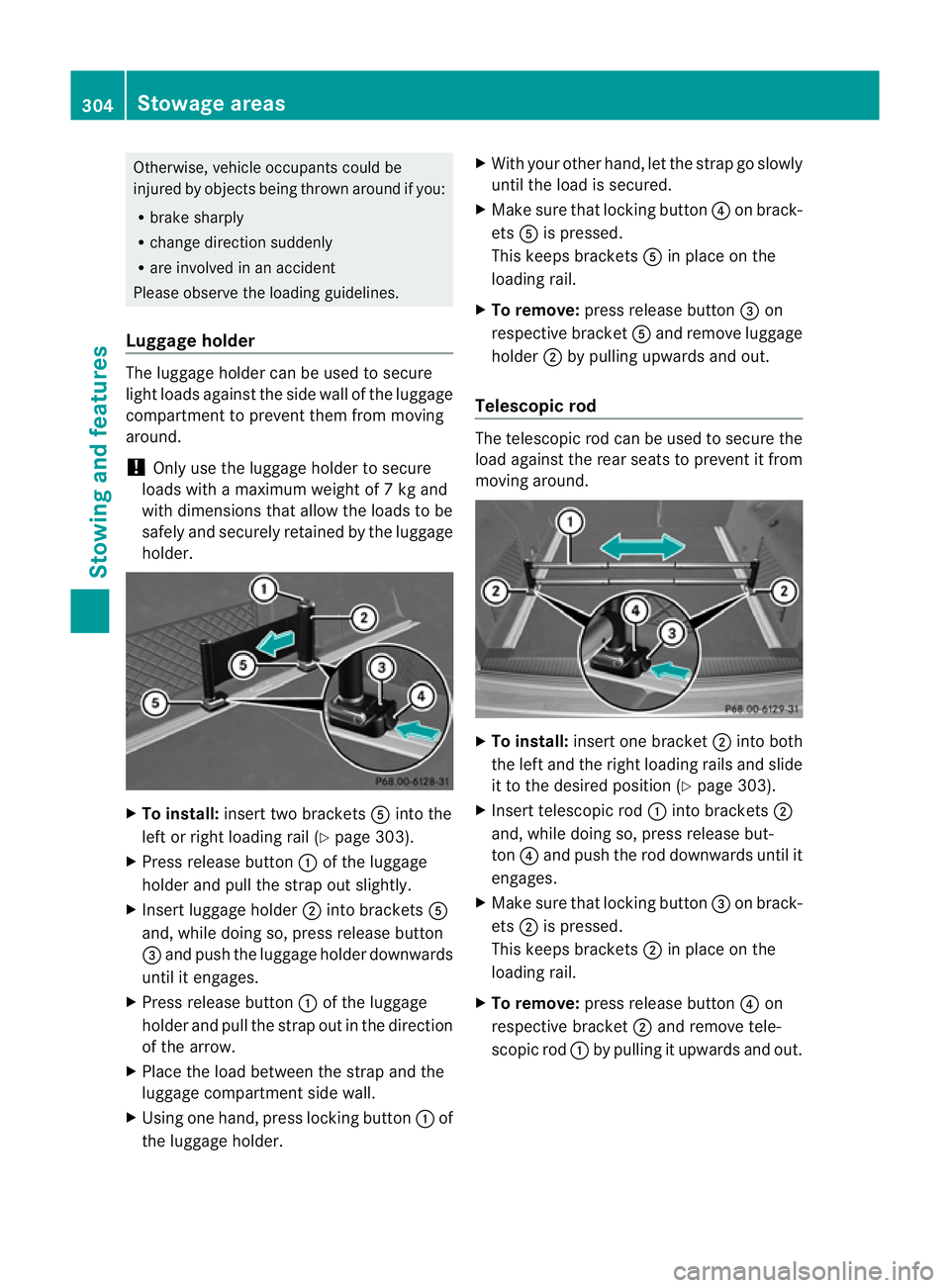
To install: insert two brackets Ainto the
left or right loading rail (Y page 303).
X Press release button :of the luggage
holder and pull the strap out slightly.
X Insert luggage holder ;into brackets A
and, while doing so, press release button
= and push the luggage holder downwards
until it engages.
X Press release button :of the luggage
holder and pull the strap out in the direction
of the arrow.
X Place the load between the strap and the
luggage compartment side wall.
X Using one hand, press locking button :of
the luggage holder. X
With your other hand, let the strap go slowly
until the load is secured.
X Make sure that locking button ?on brack-
ets Ais pressed.
This keeps brackets Ain place on the
loading rail.
X To remove: press release button =on
respective bracket Aand remove luggage
holder ;by pulling upwards and out.
Telescopic rod The telescopic rod can be used to secure the
load against the rear seats to prevent it from
moving around.
X
To install: insert one bracket ;into both
the left and the right loading rails and slide
it to the desired position (Y page 303).
X Insert telescopic rod :into brackets ;
and, while doing so, press release but-
ton ?and push the rod downwards until it
engages.
X Make sure that locking button =on brack-
ets ;is pressed.
This keeps brackets ;in place on the
loading rail.
X To remove: press release button ?on
respective bracket ;and remove tele-
scopic rod :by pulling it upwards and out. 304
Stowage areasStowing and features