2011 MERCEDES-BENZ E-Class COUPE emergency towing
[x] Cancel search: emergency towingPage 18 of 344
GVWR (Gross Vehicle Weight
Rating) (definition) .........................325
Increased vehicle weight due to
optional equipment (definition) ......324
Kilopascal (kPa) (definition) ...........325
Labeling (overview) ........................320
Load bearing index (definition) ......326
Load index ..................................... 323
Load index (definition) ...................325
Maximum loaded vehicle weight
(definition) ..................................... 325
Maximum load on a tire
(definition) ..................................... 325
Maximum permissible tire
pressure (definition) ....................... 325
Maximum tire load .........................318
Maximum tire load (definition) .......325
Optional equipment weight
(definition) ..................................... 326
PSI (pounds per square inch)
(definition) ..................................... 326
Replacing ....................................... 320
Service life ..................................... 305
Sidewall (definition) .......................326
Speed index (definition) .................325
Storing ........................................... 306
Structure and characteristics
(definition) ..................................... 324
Temperature .................................. 319
TIN (Tire Identification Number)
(definition) ..................................... 326
Tire bead (definition) ......................326
Tire pressure (definition) ................326
Tire pressures (recommended) ......324
Tire size (data) ............................... 327
Tire size designation, load-bearing
capacity, speed index ....................321
Tire tread ....................................... 305
Tire tread (definition) .....................326
Total load limit (definition) .............326
Traction ......................................... 319
Traction (definition) .......................326
Tread wear ..................................... 319
Uniform Tire Quality Grading
Standards ...................................... 318
Uniform Tire Quality Grading
Standards (definition) ....................324
Unladen weight (definition) ............325Wear indicator (definition) .............326
Wheel rim (definition) ....................325
Tires and wheels (important safety
information) ....................................... 304
Top Tether ............................................ 62
Towing Important safety guidelines ...........298
Installing the towing eye ................298
Removing the towing eye ...............299
Transmission position display ......... 157
Transmission positions .................... 157
Trip computer (on-board
computer) .......................................... 202
Trip odometer Calling up ....................................... 202
Resetting (on-board computer) ......203
Trunk
Automatic opening ........................... 84
Emergency release ..........................85
Important safety guidelines .............82
Locking separately ...........................84
Trunk lid
Display message ............................ 236
Trunk partition
Display message ............................ 237
General notes .................................. 96
Opening/closing .............................. 96
Turn signal (display message) ......... 223
Turn signals ....................................... 122
Type plate see Vehicle identification plate
U
Unlocking Emergency unlocking .......................82
From inside the vehicle (central
unlocking button) ............................. 81
V
Vanity mirror Sun visor ........................................ 256
Vehicle
Data acquisition ............................... 22
Emergency unlocking .......................82
Equipment ....................................... 18
Exterior view .................................... 24
16IndexBA 207 USA, CA Edition B 2011; 1; 3, en-USd2sboikeVersion: 3.0.3.62010-05-20T10:38:09+02:00 - Seite 16
Page 262 of 344
service subscription to a surveillance
service provider.
R the battery is sufficiently charged.
R the corresponding cellular phone network
is available for transmitting data to the
customer center.
i Determining the location of the vehicle on
a map is only possible if there is sufficient
GPS reception and the vehicle position can
be forwarded to the customer center.
The mbrace system
The mbrace system provides three different
services:
R automatic and manual emergency call
R Roadside Assistance call
R MB info call
To control the volume during an mbrace call,
proceed as follows:
XPress the W or X button on the
multifunction steering wheel.
or
XUse the volume controller of COMAND.
You can find information and a description of
all available features under "Owners Online"
at http://www.mbusa.com 22
System self-test
After you have switched on the ignition, the
system carries out a self-diagnosis.
GWarning
A malfunction in the system has been
detected if any or all of the following
conditions occur:
R The indicator lamp in the SOS button does
not come on during the system self-test.
R The indicator lamp in Roadside Assistance
button F does not come on during the
system self-test.
R The indicator lamp in Information button
ï does not come on during the system
self-test.
R The indicator lamp in the SOS button,
Roadside Assistance button F, or
Information button ï remains
illuminated constantly in red after the
system self-test.
R The message Tele Aid Inoperative or
Tele Aid Not Activated appears in the
multifunction display after the system self-
test.
If a malfunction is indicated as outlined above,
the system may not operate as expected. In
case of an emergency, help will have to be
summoned by other means.
Have the system checked at the nearest
authorized Mercedes-Benz Center or contact
the following service hotlines:
R USA: Response Center under the number
866-990-9007
R Canada: Customer Service under
1-888-923-8367.
Emergency call
Important safety notes
! A license agreement must exist in order
to activate the mbrace service. Make sure
that your system is activated and ready for
use, and press the ï MB info call button
to register. If you cannot carry out any of
the steps mentioned, the system may not
be activated.
If you have any questions concerning
activation, please contact one of the
following service hotlines:
R USA: Response Center under
866-990-9007
R Canada: Customer Service under
1-888-923-8367
22 USA only.260FeaturesLoading, stowing and features
BA 207 USA, CA Edition B 2011; 1; 3, en-USd2sboikeVersion: 3.0.3.62010-05-20T10:38:09+02:00 - Seite 260
Page 263 of 344
An emergency call is dialed automatically if
an air bag or Emergency Tensioning Device is
triggered.
i An automatically dialed mbrace
emergency call cannot be canceled.
An emergency call can also be dialed
manually.
Once the emergency call is in progress, the
indicator lamp in the SOS button flashes. The
Connecting Call message appears in the
multifunction display.
COMAND is muted.
Once a connection has been established, the
Call Connected message appears in the
multifunction display.
All important information on the emergency
is compiled, for example:
R current location of the vehicle (as
determined by the GPS system)
R vehicle model
R vehicle color
R vehicle identification number
A voice connection between the Response
Center and the occupants of the vehicle will
be established automatically soon after the
emergency call has been initiated. If the
vehicle occupants are responsive, the
Response Center attempts to get more
information on the emergency.
i If no vehicle occupant answers, an
ambulance is immediately sent to the
vehicle.GWarning
If the indicator lamp in the SOS button is
flashing continuously and there was no voice
connection to the Response Center
established, then the mbrace system could
not initiate an emergency call (e.g. the
relevant cellular phone network is not
available).
The message Call Failed appears in the
multifunction display for approximately
10 seconds.
Should this occur, assistance must be
summoned by other means.
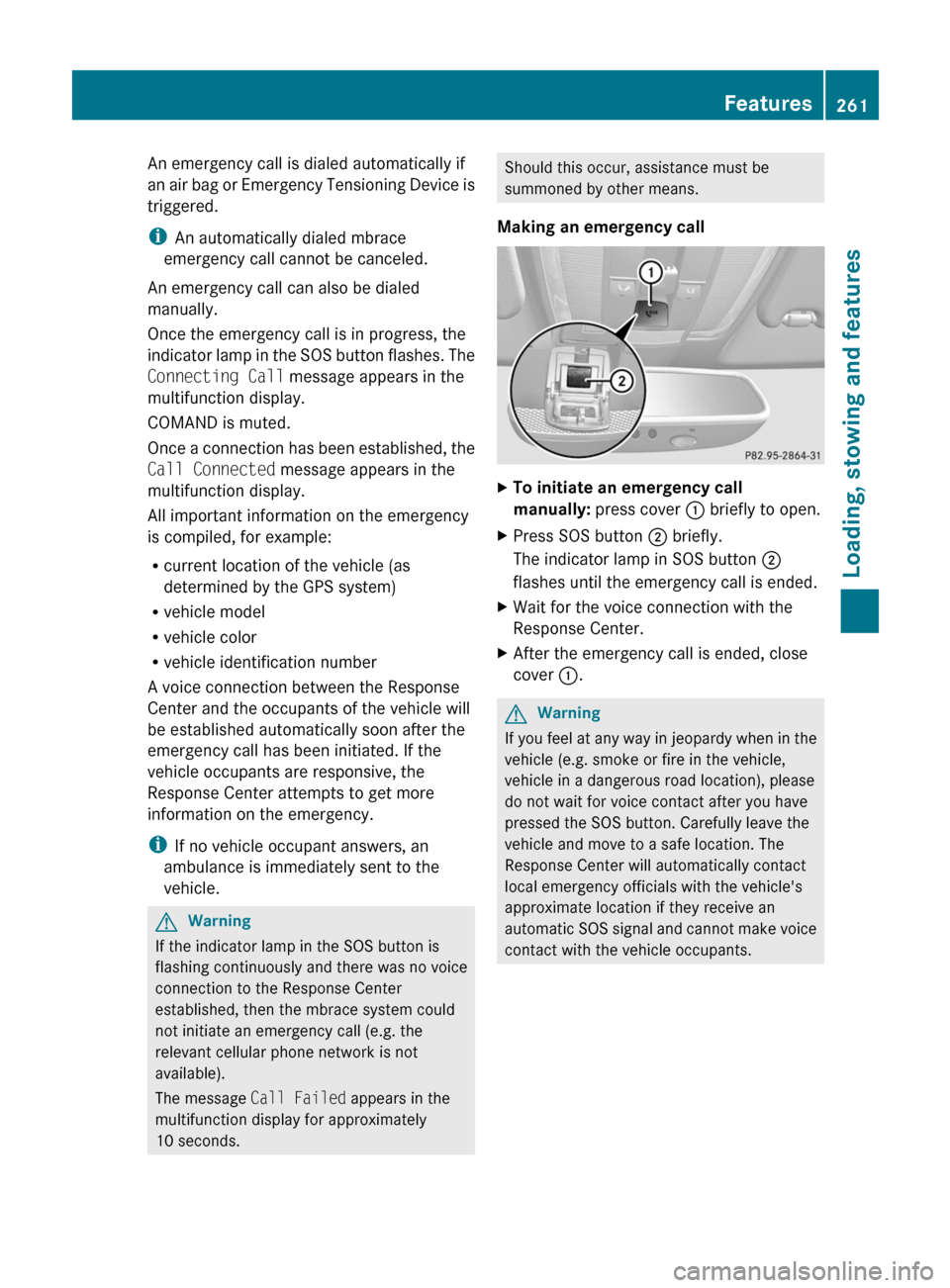
Making an emergency callXTo initiate an emergency call
manually: press cover : briefly to open.XPress SOS button ; briefly.
The indicator lamp in SOS button ;
flashes until the emergency call is ended.XWait for the voice connection with the
Response Center.XAfter the emergency call is ended, close
cover :.GWarning
If you feel at any way in jeopardy when in the
vehicle (e.g. smoke or fire in the vehicle,
vehicle in a dangerous road location), please
do not wait for voice contact after you have
pressed the SOS button. Carefully leave the
vehicle and move to a safe location. The
Response Center will automatically contact
local emergency officials with the vehicle's
approximate location if they receive an
automatic SOS signal and cannot make voice
contact with the vehicle occupants.
Features261Loading, stowing and featuresBA 207 USA, CA Edition B 2011; 1; 3, en-USd2sboikeVersion: 3.0.3.62010-05-20T10:38:09+02:00 - Seite 261Z
Page 265 of 344
established. The Connecting Call
message appears in the multifunction
display and COMAND is muted.
If a connection can be established, the Call
Connected message appears in the
multifunction display.
If a mobile phone network is available and
there is sufficient GPS reception, the mbrace
system transmits data to the Response
Center, for example:
R current location of the vehicle
R vehicle identification number
R vehicle model
R vehicle color
i The COMAND display shows that an
mbrace call is active. You can switch to the
navigation menu by pressing the NAVI
button on COMAND during the call. Spoken
commands are not available.
A voice connection between the Response
Center and the vehicle occupants is
established. You can obtain information on
how to operate your vehicle's systems, on the
location of the nearest authorized Mercedes-
Benz Center, and on further products and
services offered by Mercedes-Benz USA.
Further details on the mbrace system can be
found under http://www.mbusa.com 24
.
Log in under "Owners Online".
i If the indicator lamp in MB info call
button : flashes continuously and no
voice connection to the Response Center
has been established, then the mbrace
system has failed to initiate an MB info call
(e.g. the corresponding mobile phone
network is not available). The Call
Failed message appears in the
multifunction display.
XTo end a call: press the ~ button on the
multifunction steering wheel.
or
XPress the corresponding button for ending
a phone call on COMAND.
Call priority
An emergency call can still be initiated even
if a service call is currently active, e.g. a
Roadside Assistance call or an MB info call.
In this case, an emergency call will take
priority and override all other active calls.
The indicator lamp of the respective button
flashes until the call is ended. An emergency
call can only be terminated by the Response
Center. All other calls can be ended by
pressing the ~ button on the
multifunction steering wheel or the
corresponding button for ending a telephone
call on COMAND.
i When an mbrace call has been initiated,
COMAND is muted. The mobile phone is no
longer connected to COMAND. If you must
use your mobile phone, we recommend
that you do this only when the vehicle is
stationary and in a safe location.
Downloading destinations in COMAND
Destination Download gives you access to a
database with over 10 million points of
interest (POIs) which can be downloaded to
the navigation system of your vehicle. If you
know the destination, you can download the
address or obtain the location of points of
interest (POIs) or important destinations in
the surrounding area.
You are prompted to confirm route guidance
to the entered address.
The system calculates the route and
subsequently starts the route guidance with
the address entered.
24 USA only.Features263Loading, stowing and featuresBA 207 USA, CA Edition B 2011; 1; 3, en-USd2sboikeVersion: 3.0.3.62010-05-20T10:38:09+02:00 - Seite 263Z
Page 266 of 344
iIf you select No, the address can be stored
in the address book.
i The Destination Download function is
available if the corresponding cellular
phone network is available and data
transfer is possible.
Search & Send
"Search & Send" is a destination entry
service. You can find further information on
"Search & Send" in the separate COMAND
operating instructions.
Vehicle remote opening
If you have unintentionally locked your
vehicle (e.g. the SmartKey is inside the
vehicle) and a replacement key is not
available:
XContact the following service hotlines:
R USA: Response Center under the
number 866-990-9007
R Canada: Customer Service under
1-888-923-8367
You will be asked for your password.XReturn to your vehicle at the time arranged
with the Response Center.XPull the trunk handle for at least 20
seconds until the indicator lamp in the SOS
button ( Y page 260) flashes.
The Connecting Call message appears in
the multifunction display.
Alternatively, the vehicle can also be opened
via the Internet in the "Owners Online"
section using your ID number and
password 25
.
i Vehicle remote unlocking is only possible
if the corresponding cellular phone
network is accessible.
The SOS button flashes and the
Connecting Call message appears in the
multifunction display to confirm that the
command for vehicle remote unlocking has
been received.
If you pull the trunk handle for more than
20 seconds before receiving authorization
for remote unlocking, you must wait 15
minutes before you can pull on the handle
of the trunk lid again.
Vehicle remote closing in an emergency
If you forget to lock your vehicle but are no
longer in the vicinity of the vehicle, it can be
locked for you by the Response Center.
The vehicle can be locked remotely up to four
days after the ignition was last switched off.
XContact the following service hotlines:
R USA: Response Center under
866-990-9007
R Canada: Customer Service under
1-888-923-8367
You will be asked for your PIN.
The next time you are in your vehicle and
switch on the ignition, the Tele Aid Doors
locked by remote control message
appears in the multifunction display.
i The vehicle remote locking feature is
available when the relevant mobile phone
network is available and data connection is
possible.
Stolen Vehicle Recovery Services
If your vehicle has been stolen:
XContact the police.
The police will issue an incident report. This
report has a number.XThis number will be forwarded to the
Response Center together with your PIN.
The Response Center will then attempt to
covertly contact the mbrace system. The
Response Center contacts you and the
local law enforcement authority if the
vehicle is located. However, only the law25 USA only.264FeaturesLoading, stowing and features
BA 207 USA, CA Edition B 2011; 1; 3, en-USd2sboikeVersion: 3.0.3.62010-05-20T10:38:09+02:00 - Seite 264
Page 290 of 344
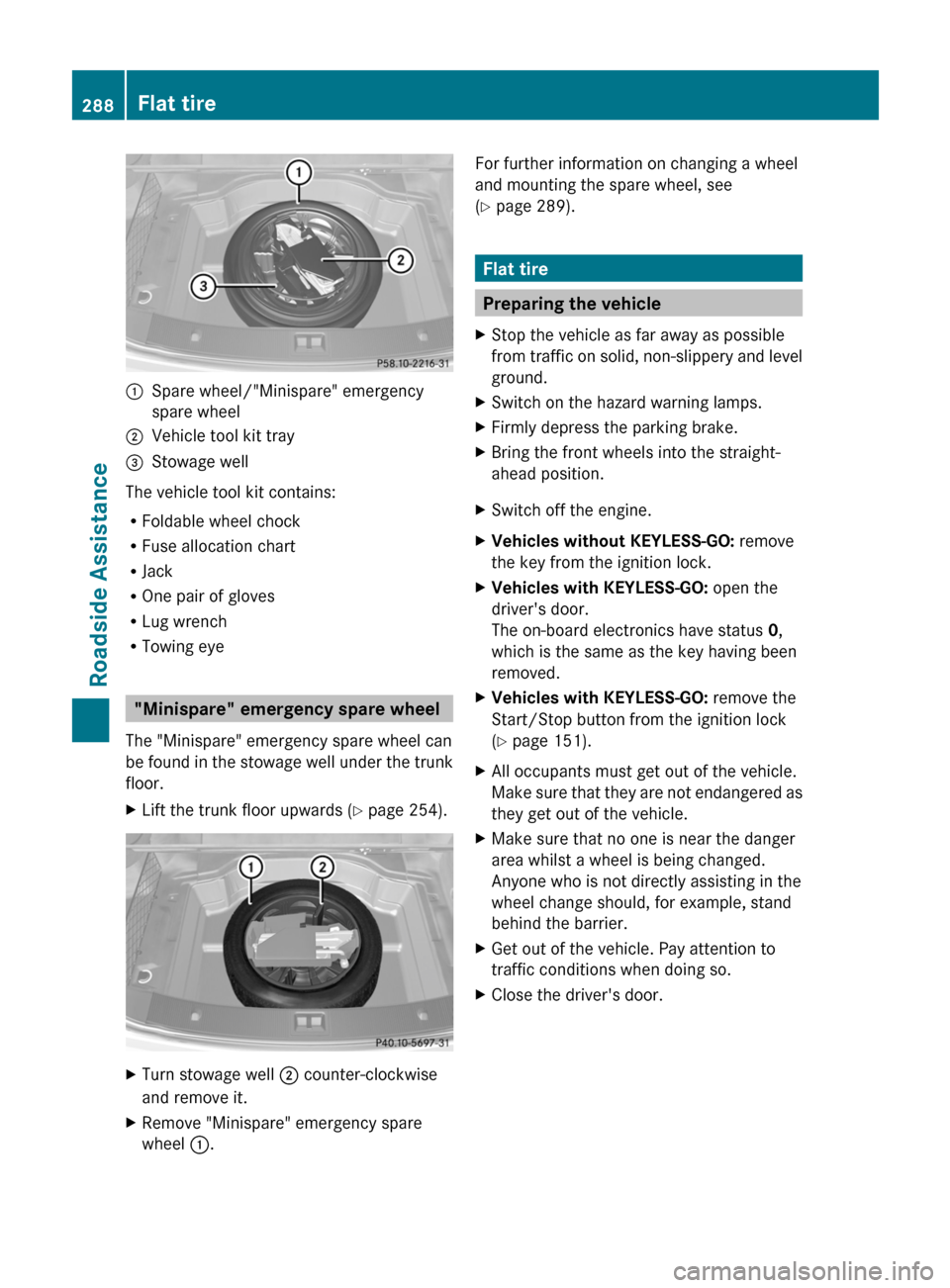
:Spare wheel/"Minispare" emergency
spare wheel
;Vehicle tool kit tray=Stowage well
The vehicle tool kit contains:
RFoldable wheel chock
RFuse allocation chart
RJack
ROne pair of gloves
RLug wrench
RTowing eye
"Minispare" emergency spare wheel
The "Minispare" emergency spare wheel can
be found in the stowage well under the trunk
floor.
XLift the trunk floor upwards (Y page 254).XTurn stowage well ; counter-clockwise
and remove it.
XRemove "Minispare" emergency spare
wheel :.
For further information on changing a wheel
and mounting the spare wheel, see
(Y page 289).
Flat tire
Preparing the vehicle
XStop the vehicle as far away as possible
from traffic on solid, non-slippery and level
ground.
XSwitch on the hazard warning lamps.XFirmly depress the parking brake.XBring the front wheels into the straight-
ahead position.
XSwitch off the engine.XVehicles without KEYLESS-GO: remove
the key from the ignition lock.
XVehicles with KEYLESS-GO: open the
driver's door.
The on-board electronics have status 0,
which is the same as the key having been
removed.
XVehicles with KEYLESS-GO: remove the
Start/Stop button from the ignition lock
(Y page 151).
XAll occupants must get out of the vehicle.
Make sure that they are not endangered as
they get out of the vehicle.
XMake sure that no one is near the danger
area whilst a wheel is being changed.
Anyone who is not directly assisting in the
wheel change should, for example, stand
behind the barrier.
XGet out of the vehicle. Pay attention to
traffic conditions when doing so.
XClose the driver's door.288Flat tireRoadside Assistance
BA 207 USA, CA Edition B 2011; 1; 3, en-USd2sboikeVersion: 3.0.3.62010-05-20T10:38:09+02:00 - Seite 288
Page 320 of 344
Trailer load/noseweight
The trailer load/noseweight affects the gross
weight of the vehicle. If a trailer is attached,
the trailer load/noseweight is included in the
load along with occupants and luggage. The
trailer load/noseweight is usually
approximately 10% of the gross weight of the
trailer and its cargo.
Your Mercedes-Benz is designed for
transporting persons and their luggage.
Mercedes-Benz does not recommend towing
a trailer with your vehicle.
Maximum tire load
GWarning
Do not overload the tires by exceeding the
specified load limit as indicated on the Tire
and Loading Information placard on the
driver's door B-pillar. Overloading the tires
can overheat them, possibly causing a
blowout. Overloading the tires can also result
in handling or steering problems, or brake
failure.
i The actual values for tires are specific to
each vehicle and may deviate from the
values in the illustration.
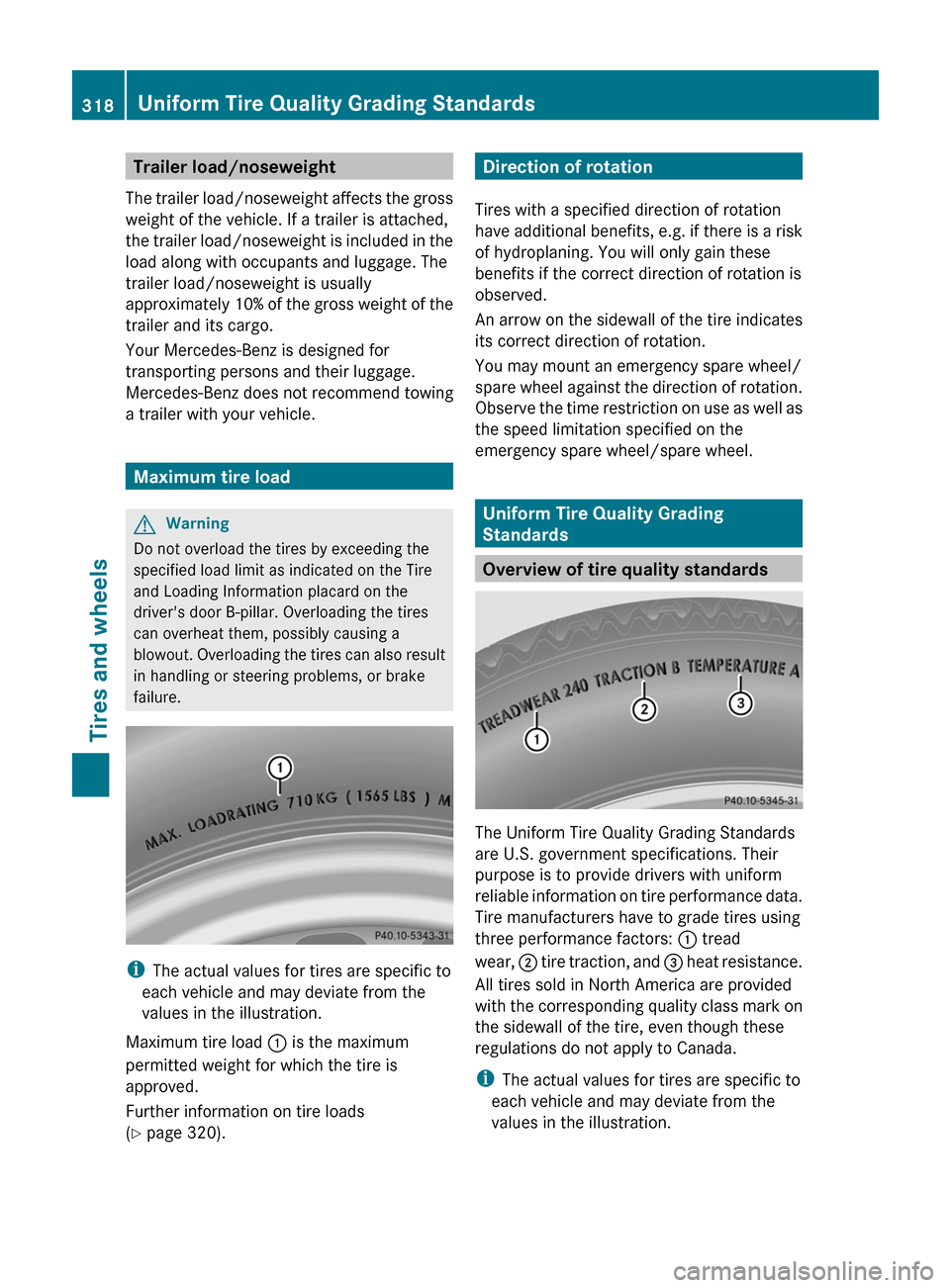
Maximum tire load : is the maximum
permitted weight for which the tire is
approved.
Further information on tire loads
( Y page 320).
Direction of rotation
Tires with a specified direction of rotation
have additional benefits, e.g. if there is a risk
of hydroplaning. You will only gain these
benefits if the correct direction of rotation is
observed.
An arrow on the sidewall of the tire indicates
its correct direction of rotation.
You may mount an emergency spare wheel/
spare wheel against the direction of rotation.
Observe the time restriction on use as well as
the speed limitation specified on the
emergency spare wheel/spare wheel.
Uniform Tire Quality Grading
Standards
Overview of tire quality standards
The Uniform Tire Quality Grading Standards
are U.S. government specifications. Their
purpose is to provide drivers with uniform
reliable information on tire performance data.
Tire manufacturers have to grade tires using
three performance factors: : tread
wear, ; tire traction, and = heat resistance.
All tires sold in North America are provided
with the corresponding quality class mark on
the sidewall of the tire, even though these
regulations do not apply to Canada.
i The actual values for tires are specific to
each vehicle and may deviate from the
values in the illustration.
318Uniform Tire Quality Grading StandardsTires and wheels
BA 207 USA, CA Edition B 2011; 1; 3, en-USd2sboikeVersion: 3.0.3.62010-05-20T10:38:09+02:00 - Seite 318