2011 MERCEDES-BENZ E-CLASS CABRIOLET seats
[x] Cancel search: seatsPage 113 of 353

X
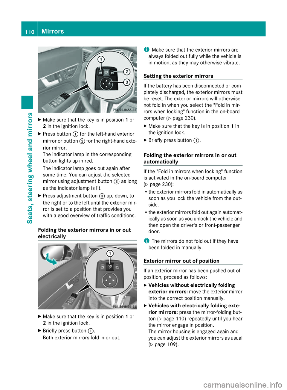
Make sure that the key is in position 1or
2 in the ignition lock.
X Press button :for the left-hand exterior
mirror or button ;for the right-hand exte-
rior mirror.
The indicator lamp in the corresponding
button lights up in red.
The indicator lamp goes out again after
some time. You can adjust the selected
mirror using adjustment button =as long
as the indicator lamp is lit.
X Press adjustment button =up, down, to
the right or to the left until the exterior mir-
ror is set to aposition that provides you
with agood overview of traffic conditions.
Folding the exterior mirrors in or out
electrically X
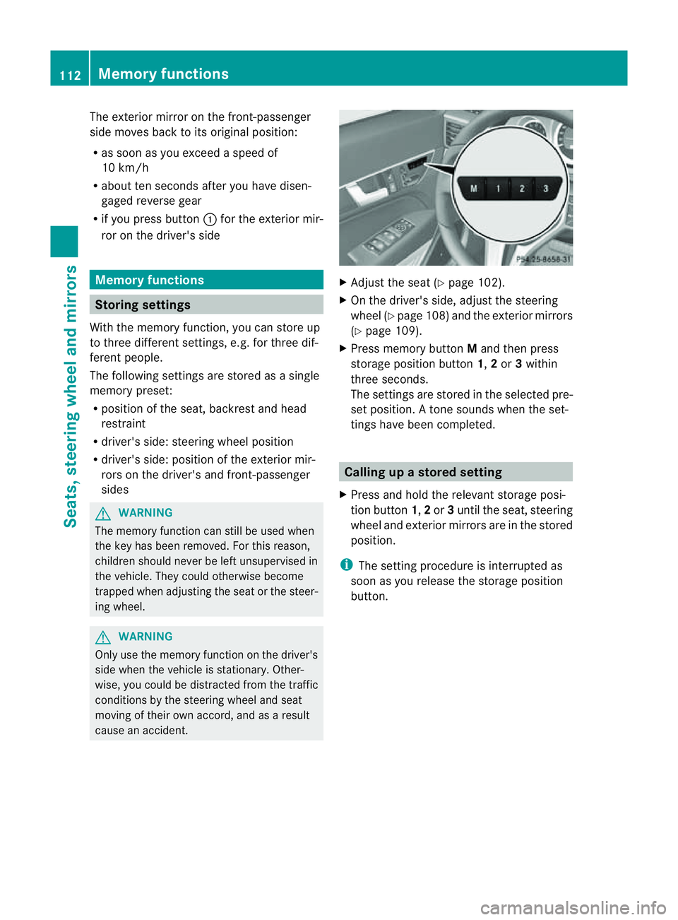
Make sure that the key is in position 1or
2 in the ignition lock.
X Briefly press button :.
Both exterior mirrors fold in or out. i
Make sure that the exterior mirrors are
always folded out fully while the vehicle is
in motion, as they may otherwise vibrate.
Setting the exterior mirrors If the battery has been disconnected or com-
pletely discharged, the exterior mirrors must
be reset. The exterior mirrors will otherwise
not fold in when you select the "Fold in mir-
rors when locking" function in the on-board
computer (Y
page 230).
X Make sure that the key is in position 1in
the ignition lock.
X Briefly press button :.
Folding the exterior mirrors in or out
automatically If the "Fold in mirrors when locking" function
is activated in the on-board computer
(Y
page 230):
R the exterior mirrors fold in automatically as
soon as you lock the vehicle from the out-
side.
R the exterior mirrors fold out again automat-
ically as soon as you unlock the vehicle and
then open the driver's or front-passenger
door.
i The mirrors do not fold out if they have
been folded in manually.
Exterior mirror out of position If an exterior mirror has been pushed out of
position, proceed as follows:
X
Vehicles without electrically folding
exterior mirrors: move the exterior mirror
into the correct position manually.
X Vehicles with electrically folding exte-
rior mirrors: press the mirror-folding but-
ton (Y page 110) repeatedly until you hear
the mirror engage in position.
The mirror housing is engaged again and
you can adjust the exterior mirrors as usual
(Y page 109). 110
MirrorsSeats, steering wheela
nd mirrors
Page 114 of 353

Automati
canti-dazzle mirrors G
WARNING
If inciden tlight fro mheadlamps is prevented
from striking the sensor in the rear-view mir-
ror, for instance, by luggage piled too high in
the vehicle, the mirror's automatic anti-dazzle
function will not operate.
Incident light could then blind you. This may
distrac tyou from the traffic conditions and,
as aresult, you may cause an accident.
The rear-view mirror and the exterior mirror
on the driver's side automatically go into anti-
dazzle mode if the ignition is switched on and
inciden tlight fro mheadlamps strikes the sen-
sor in the rear-view mirror.
The mirror sdonot go intoa nti-dazzle mode if
revers egear is engaged. Parking position for the exterior mir-
ror on the front-passenger side
Setting and storing the parking position You can position the front-passenger side
exterior mirror in such away that you can see
the rear wheel on that side as soon as you
engage revers egear. You can stor ethis posi-
tion. X
Make sure that the vehicle is stationary and
that the key is in position 2in the ignition
lock.
X Press button ;for the exterior mirror on
the front-passenger side. X
Engage revers egear.
The exterior mirror on the front-passenger
side moves to the preset parkin gposition.
X Use adjustment button =to adjust the
exterior mirror to aposition that allows you
to see the rear wheel and the kerb.
The parkin gposition is stored.
i If you shift the transmission to another
position ,the exterior mirror on the front-
passenger side return stothe driving posi-
tion.
i You can also stor ethe parkin gposition
using memory button M?.
X Make sure that the key is in position
2in the ignition lock.
X With the exterior mirror on the front-
passenger side activated, use adjust-
ment button =to adjust the exterior
mirror to aposition which allows you
to see the rear wheel and the kerb.
X Press memory button M? and one of
the arrows on adjustment button =
within three seconds.
The parkin gposition is stored if the
exterior mirror does not move.
If the mirror moves out of position ,repeat
the steps.
Calling up astore dparking position set-
ting X
Tur nthe key to position 2in the ignition
lock.
X Adjust the exterior mirror on the front-
passenger side with the corresponding but-
ton (Y page 109).
X Engage reverse gear.
The exterior mirror on the front-passenger
side moves to the stored parking position. Mirrors
111Seats, steering wheela nd mirrors Z
Page 115 of 353

The exterior mirror on the front-passenger
side moves back to its original position:
R
as soon as you exceed aspeed of
10 km/h
R about ten seconds after you have disen-
gaged reverse gear
R if you press button :for the exterior mir-
ror on the driver's side Memory functions
Storing settings
With the memory function, you can store up
to three different settings, e.g. for three dif-
ferent people.
The following settings are stored as asingle
memory preset:
R position of the seat, backrest and head
restraint
R driver's side: steerin gwheel position
R driver's side: position of the exterior mir-
rors on the driver's and front-passenger
sides G
WARNING
The memory function can still be used when
the key has been removed. For this reason,
children should never be left unsupervised in
the vehicle. They could otherwise become
trapped when adjusting the seat or the steer-
ing wheel. G
WARNING
Only use the memory function on the driver's
side when the vehicle is stationary. Other-
wise, you could be distracted from the traffic
conditions by the steerin gwheel and seat
moving of their own accord, and as aresult
cause an accident. X
Adjust the seat (Y page 102).
X On the driver's side, adjust the steering
wheel (Y page 108) and the exterior mirrors
(Y page 109).
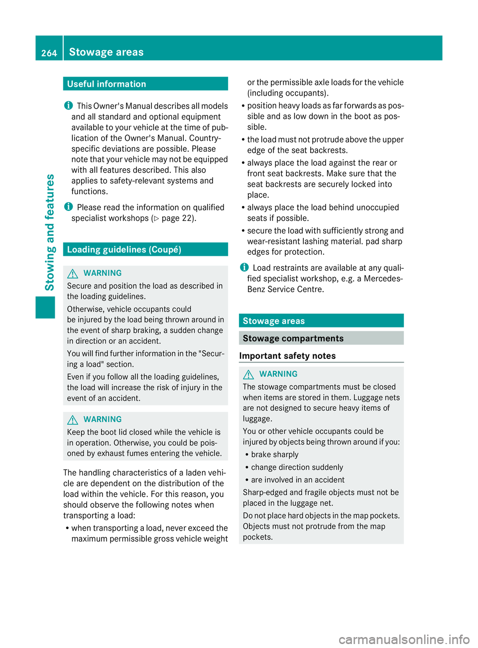
X Press memory button Mand then press
storage position button 1,2or 3within
three seconds.
The settings are stored in the selected pre-
set position. Atone sounds when the set-
tings have been completed. Calling up
astore dsetting
X Pres sand hold th erelevant storage posi-
tio nb utton 1,2or 3until th eseat ,steering
wheel and exterio rmirrors are in the stored
position.
i The settin gprocedure is interrupted as
soon as you release the storage position
button. 112
Memory functionsSeats, steering wheel and mirrors
Page 119 of 353

Rear foglamp
X
To switc honthe rear foglamp: turn the
key in the ignition lock to position 2or start
the engine.
X Turn the light switch to LorÃ.
X Press the Rbutton.
The yellow Rindicator lamp in the
instrument cluster lights up.
X To switc hoff the rear foglamp: press the
R button.
The yellow Rindicator lamp in the
instrument cluster goe sout.
Vehicles with front foglamps: when the light
switch is in the Tposition, the rea rfog-
lamp can only be switched on if the foglamps
(without dipped-beam headlamps) are
switched on.
i If you switch the engine off (key in posi-
tion 1in the ignition lock) and then restart
it, the previous rear foglamp settings are
restored.
Adjusting the headlam prange (halogen
headlamps) The headlamp range control allow
syou to
adjust the cone of light from the headlamps
to sui tthe vehicle load. g
Driver's seat and front-passenger seat
occupied
1 Driver's seat, front-passenger seat and
rear seats occupied 2
Driver's seat, front-passenger seat and
rear seats occupied, boot laden
3 Driver's and front-passenger seats occu-
pied and maximum permissible rear axle
load utilised, e.g. when towing atrailer
X Start the engine.
X Turn headlamp range control to the posi-
tion which corresponds to the load in your
vehicle.
Headlampc leaning system The headlamps are cleaned automatically if
the "Wipe with washer fluid" function is oper-
ated ten times while the light
sare on and the
engin eisrunning (Y page 124). When you
switc hoff the ignition, the automatic head-
lamp cleaning syste misreset and counting is
resumed from 0. Combination switch
Turns ignals :
Main-beam headlamps
; Turn signal, right
= Headlamp flasher
? Turn signal, left 116
Exterior lightingLights and windscreen wipers
Page 190 of 353

the minimum
,the distance ma ynolongerbe
shown.
Warning displays The warning displays show the distance
between the sensors and the obstacle. The
warning displayf or the front area is located
on the dashboard above the centre air vents.
The warning displayf or the rear area in the
Coupéisl ocated on the roof lining in the rear
compartment;int he Cabriolet, it is between
the rear seats. Warning displayf
or the front area
: Segmentsont he left-hand side of the
vehicle
; Segmentsont he right-hand side of the
vehicle
= Segmentss howing operational readiness
The warning displayf or each side of the vehi-
cle is divided into five yellow and two red seg-
ments. PARKTRONIC is operational if yellow
segments showing operational readiness =
light up.
The gear lever position or the transmission
position of the automatic transmission deter-
mines which warning displayisa ctive when
the engine is running. Manual transmission: Gear lever posi-
tion Warning display
Forwards gear
or
Neutral
Front area activated
Reverse gear
Rear and front areas
activated
Automatic transmission:
Transmission
position Warning display
D
Front area activated
R
or N Rear and front areas
activated
P
No areas activated
One or more segments light up as the vehicle
approaches an obstacle, depending on the
vehicle's distance from the obstacle.
From the:
R
sixth segment onwards, you will hear an
intermittent warning tone for approx-
imately two seconds.
R seventh segment onwards, you will hear a
warning tone for approximately two sec-
onds. This indicates that you have now
reached the minimum distance. Driving systems
187Driving and parking Z
Page 267 of 353

Useful information
i This Owner's Manual describes all models
and all standard and optional equipment
available to your vehicle at the time of pub-
lication of the Owner's Manual. Country-
specific deviation sare possible. Please
not ethat your vehicle may not be equipped
with all feature sdescribed. This also
applies to safety-relevan tsystems and
functions.
i Pleas ereadt he information on qualified
specialist workshop s(Ypage 22). Loading guidelines (Coupé)
G
WARNING
Secur eand position th eload as described in
th el oadin gguidelines.
Otherwise ,vehicl eoccupant scould
be injured by th eload bein gthrow na round in
the event of sharp braking, asudden change
in directio noranaccident.
You willf ind further informatio ninthe "Secur-
ing aload" section.
Even if you follow all the loading guidelines,
the load will increase the risk of injury in the
event of an accident. G
WARNING
Keep the boot lid closed while the vehicle is
in operation. Otherwise, you could be pois-
oned by exhaust fumes enteringt he vehicle.
The handling characteristics of aladen vehi-
cle are dependent on the distribution of the
load within the vehicle. For this reason, you
should observe the following notes when
transporting aload:
R when transporting aload, never exceed the
maximum permissible gross vehicle weight or the permissible axle loads for the vehicle
(including occupants).
R position heavy loads as far forwards as pos-
sible and as low down in the boot as pos-
sible.
R the load must not protrude above the upper
edge of the seat backrests.
R always place the load against the rear or
front seat backrests. Make sure that the
seat backrests are securely locked into
place.
R always place the load behind unoccupied
seats if possible.
R secure the load with sufficiently stronga nd
wear-resistant lashing material. pad sharp
edges for protection.
i Load restraintsa re available at any quali-
fied specialist workshop, e.g. aMercedes-
Benz Service Centre. Stowage areas
Stowage compartments
Important safety notes G
WARNING
The stowage compartments must be closed
when items are stored in them. Luggage nets
are not designed to secure heavy items of
luggage.
You or other vehicle occupants could be
injured by objectsb eing thrown around if you:
R brake sharply
R change direction suddenly
R are involved in an accident
Sharp-edged and fragile objectsm ust not be
placed in the luggagen et.
Do not place hard objectsint he map pockets.
Objectsm ust not protrude from the map
pockets. 264
Stowage areasStowing and features
Page 324 of 353

Tyre pressure
Tyre pressure specifications
Yo uw illf ind atable of tyr epressures for var-
ious operating conditions on the insid eof
your vehicle's fuel fille rflap.
Operation with emergency spare wheel:
The applicable value for the emergency spare
wheel is stated on the spare wheel and in the
technical data section.
Operation with atrailer: The applicable
value for the rear tyre sisthe maximum tyre
pressure value stated on the table insid ethe
fuel filler flap.
The table insid ethe fuel filler flap may state
tyre pressures for differen tload conditions.
These are defined in the table as different
numbers of passengers and amounts of lug-
gage. The actual number of seats may vary –
for more information please refer to the vehi-
cle's registration documents.
If no other data is stated, the tyre pressures
specified on the fuel filler flap apply for all
tyres approved for this vehicle. If
at yre size precedes atyre pressure, the tyre
pressure information following is only valid
for that tyre size. Instead of the complete tyre size, the rim
diameter alone, for example
R16,may be lis-
ted. Rim diameter
:is part of the tyre size and
can be found on the tyre sidewall. G
WARNING
Tyre pressure that is either too high or too low
has anegative effect on the vehicle's driving
safety, which could lead you to cause an acci-
dent. Therefore, you should regularly check
the pressure of all the tyres, particularly prior
to long trips, and correc tthe pressure as nec-
essary.
To test tyre pressure, use asuitable pressure
gauge. The outer appearance of atyre does
not permit any reliablec onclusion about the
tyre pressure. G
WARNING
Do not fit anything else to the tyre valve other
than the standard valve cap. In particular, ret-
rofitted tyre pressure monitors which are
screwed on to the valve may overload it and
cause it to fail. Due to their design, the valve Tyrep
ressure
321Wheels and tyres
Z
Page 333 of 353

Useful information
i This Owner's Manual describes all models
and all standard and optional equipment
available to your vehicle at the time of pub-
lication of the Owner's Manual. Country-
specific deviation sare possible. Please
not ethat your vehicle may not be equipped
with all feature sdescribed. This also
applies to safety-relevan tsystems and
functions.
i Pleas ereadt he information on qualified
specialist workshop s(Ypage 22). Note
sont hetechnical data
i The technical dat awas determined in
accordance wit hECDirectives .Alldata
applies to th evehicle's standard equip-
ment. Therefore, th edatam ay differ for
vehicles wit hoptional equipment. You can
obtain further information from a
Mercedes-Ben zServi ce Centre.
You can fin dtechnic al dataonthe Internet at:
http://www.mercedes-benz.com Genuin
eMercedes-Ben zparts
Mercedes-Ben ztests genuine parts and con-
version parts and accessories which have
been specifically approved for your vehicle for
their reliability, safety and suitability. Despite
ongoin gmarket research ,Mercedes-Benz is
unable to evaluate other parts. Mercedes-
Benzt herefore accepts no responsibility for
the use of such parts in Mercedes-Ben zvehi-
cles, even if they have been independently or
officially approved.
In Germany and some other countries, certain
parts are only officially approved for installa-
tion or modification if they comply with legal
requirements. All genuine Mercedes-Benz
parts meet this requirement .The use of non- approved parts may invalidate the vehicle's
general operating permit. This is the case if:
R
they cause achange of the vehicle type
from that for which the vehicle's general
operating permit was granted.
R other road users could be endangered.
R the emission or noise levels are adversely
affected. G
WARNING
Driving safety may be impaired if non-
approved parts, tyres and wheels or safety-
relevant accessories are used.
This could lead to malfunctions in safety-rel-
evant systems, e.g. the brake system. This
could cause you to lose control of your vehicle
and cause an accident.
For this reason, Mercedes-Ben zrecommends
that you use genuine Mercedes-Benz parts or
parts of equal quality. Only use tyres, wheels
and accessories that have been specifically
approved for your vehicle.
! Airbags and seat belt tensioners, as well
as control units and sensor sfor these
restraint systems may be installed in the
following areas of your vehicle:
R doors
R door pillars
R door sills
R seats
R dashboard
R instrument cluster
R centre console
Do not install accessories such as audio
systems in these areas. Do not carry out
repairs or welding. You could impair the
operatin gefficiency of the restraint sys-
tems.
Have aftermarket accessories installed at
aq ualified specialist workshop. Mercedes-
Benz recommends that you use a
Mercedes-Benz Service Centr efor this pur-
pose. 330
Genuine Mercedes-Benz partsTechnical data