2011 MERCEDES-BENZ C-CLASS ESTATE ECU
[x] Cancel search: ECUPage 346 of 401
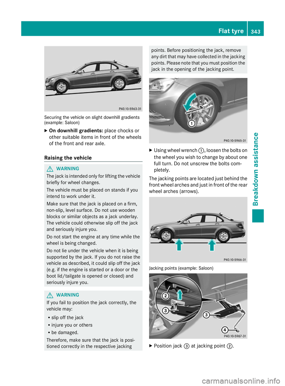
Securing the vehicle on slight downhill gradients
(example: Saloon)
X
On downhill gradients: place chocks or
othe rsuitable items in fron tofthe wheels
of the front and rear axle.
Raising the vehicle G
WARNING
The jack is intended only for lifting the vehicle
briefly for wheel changes.
The vehicle must be placed on stands if you
intend to work under it.
Make sure that the jack is placed on a firm,
non-slip, level surface. Do not use wooden
blocks or similar objects as a jack underlay.
The vehicle could otherwise slip off the jack
and seriously injure you.
Do not start the engine at any time while the
wheel is being changed.
Do not lie under the vehicle when it is being
supported by the jack. If you do not raise the
vehicle as described, it could slip off the jack
(e.g. if the engine is started or a door or the
boot lid/tailgate is opened or closed) and
seriously injure you. G
WARNING
If you fail to position the jack correctly, the
vehicle may:
R slip off the jack
R injure you or others
R be damaged.
Therefore, make sure that the jack is posi-
tioned correctly in the respective jacking points. Before positioning the jack, remove
any dirt that may have collected in the jacking
points. Please note that you must position the
jack in the opening of the jacking point.
X
Using wheel wrench :, loosen the bolts on
the wheel you wish to change by about one
full turn. Do not unscrew the bolts com-
pletely.
The jacking points are located just behind the
front wheel arches and just in front of the rear
wheel arches (arrows). Jacking points (example: Saloon)
X
Position jack =at jacking point ;. Flat tyre
343Breakdown assistance Z
Page 348 of 401
X
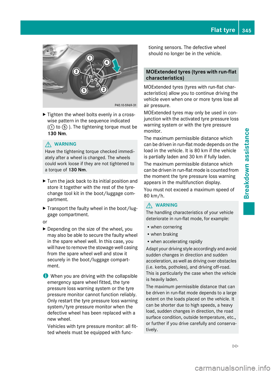
Tighten the wheel bolts evenly in a cross-
wise pattern in the sequence indicated
(: toA ). The tightening torque must be
130 Nm. G
WARNING
Have the tightening torque checked immedi-
ately after a wheel is changed. The wheels
could work loose if they are not tightened to
a torque of 130 Nm.
X Turn the jack back to its initial position and
store it together with the rest of the tyre-
change tool kit in the boot/luggage com-
partment.
X Transport the faulty wheel in the boot/lug-
gage compartment.
or
X Depending on the size of the wheel, you
may also be able to secure the faulty wheel
in the spare wheel well. In this case, you
will have to remove the stowage well casing
from the spare wheel well and stow it
securely in the boot/luggage compart-
ment.
i When you are driving with the collapsible
emergency spare wheel fitted, the tyre
pressure loss warning system or the tyre
pressure monitor cannot function reliably.
Only restart the tyre pressure loss warning
system/tyre pressure monitor when the
defective wheel has been replaced with a
new wheel.
Vehicles with tyre pressure monitor: all fit-
ted wheels must be equipped with func- tioning sensors. The defective wheel
should no longer be in the vehicle. MOExtended tyres (tyres with run-flat
characteristics)
MOExtended tyres (tyres with run-flat char-
acteristics) allow you to continue driving the
vehicle even when one or more tyres lose all
air pressure.
MOExtended tyres may only be used in con-
junction with the activated tyre pressure loss
warning system or with the tyre pressure
monitor.
The maximum permissible distance which
can be driven in run-flat mode depends on the
load in the vehicle. It is 80 km if the vehicle
is partially laden and 30 km if fully laden.
The maximum permissible distance which
can be driven in run-flat mode is counted from
the moment the tyre pressure loss warning
appears in the multifunction display.
You must not exceed a maximum speed of
80 km/h. G
WARNING
The handling characteristics of your vehicle
deteriorate in run-flat mode, for example:
R when cornering
R when braking
R when accelerating rapidly
Adapt your driving style accordingly and avoid
sudden changes in direction and sudden
acceleration, as well as driving over obstacles
(i.e. kerbs, potholes), and driving off-road.
This is particularly the case when the vehicle
is heavily laden.
The maximum permissible distance that can
be driven in run-flat mode depends to a large
exten tonthe loads placed on the vehicle. It
can be shorter due to high speeds, a heavy
load, sudden changes in direction, the road
surface condition, outside temperature, etc.,
or further if you drive carefully and conserva-
tively. Flat tyre
345Breakdown assistance
Z
Page 351 of 401
X
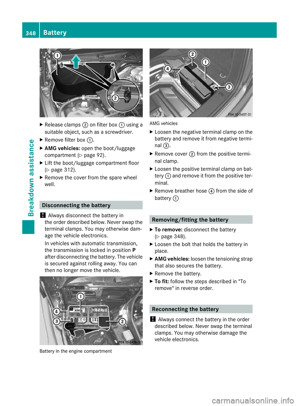
Release clamps ;on filter box :using a
suitable object, such as a screwdriver.
X Remove filter box :.
X AMG vehicles: open the boot/luggage
compartment (Y page 92).
X Lif tthe boot/luggage compartmentf loor
(Y page 312).
X Remove the cover fro mthe spare wheel
well. Disconnecting the battery
! Always disconnectt he battery in
the order described below. Never swap the
terminal clamps. You may otherwise dam-
age the vehicle electronics.
In vehicles with automatic transmission,
the transmission is locked in position P
after disconnecting the battery. The vehicle
is secured against rolling away.Y ou can
then no longer move the vehicle. Battery in the engine compartment AMG vehicles
X
Loosen the negative terminal clamp on the
battery and remove it from negative termi-
nal =.
X Remove cover ;from the positive termi-
nal clamp.
X Loosen the positive terminal clamp on bat-
tery :and remove it from the positive ter-
minal.
X Remove breather hose ?from the side of
battery : Removing/fitting the battery
X To remove: disconnect the battery
(Y page 348).
X Loosen the bolt that holds the battery in
place.
X AMG vehicles: loosen the tensioning strap
that also secures the battery.
X Remove the battery.
X To fit: follow the steps described in "To
remove" in reverse order. Reconnecting the battery
! Always connect the battery in the order
described below. Never swap the terminal
clamps. You may otherwise damage the
vehicle electronics. 348
BatteryBreakdown assistance
Page 352 of 401
X
Switch off all electrical consumers (e.g.
radio, blower, etc.).
X Connect the positive terminal clamp and
secure the cover.
X Connect the negative terminal clamp.
X Battery in the engine compartment: put
the filter box back in place.
X Clip in the filter box's retaining clamps and
close them.
X Close the bonnet.
X AMG vehicles: fold downand close the
boot/luggage compartment floor.
X Close the boot/luggage compartment.
i If the powe rsupply has been interrupted,
e.g. if you reconnect the battery, you will
have to:
R set the clock; see the separate operating
instructions.
R reset the function for automatically fold-
ing the exterio rmirrors in/out by folding
the mirrors out once (Y page 113).Charging the battery
G
WARNING
Only charge the battery in a well-ventilated
area. As the battery is being charged, gases
can escape and generate minor explosions.
This could injure you and other persons or
cause damage to the paintwork or acid cor-
rosio nont he vehicle.
You can obtain information about battery
chargers which allow the battery to be
charged while still installed from a qualified
specialist workshop, e.g. aMercedes-Benz
Service Centre. G
WARNING
There is a risk of acid burns during the charg-
ing process due to the gases which escape
from the battery. Do not lean over the battery
during the charging process. G
WARNING
Battery acid is caustic. Avoid contact with the
skin, eyes or clothing.
! Only charge the installed battery with a
battery charger which has been tested and
approved by Mercedes-Benz .These battery
chargers allow the battery to be charged
while still installed.
! Only use battery chargers with a maxi-
mum charging voltage of 14.8 V.
! Only charge the battery using the jump-
start connection point.
The jump-starting connection point is in the
engine compartment (Y page 350).
X Open the bonnet (Y page 322).
X Connect the battery charger to the positive
terminal and earth point in the same order
as when connecting the donor battery in
the jump-starting procedure
(Y page 350).
X Read the battery charger's operating
instructions before charging the battery. Battery
349Breakdown assistance Z
Page 355 of 401
Before towing away, make sure that the steer-
ing can be moved and is not locked.
If you tow or tow-start another vehicle, its
weight must not exceed the maximum per-
missible gross vehicle weigh
tofyour vehicle. G
WARNING
The vehicle is braked when the HOLD function
or DISTRONIC PLUS is activated. Therefore,
deactivate HOLD and DISTRONIC PLUS if the
vehicle is to be towed.
It is better to have the vehicle transported
than to have it towed.
! You may tow the vehicle for a maximum
of 50 km. A towing speed of 50 km/hm ust
no tb e exceeded.
For towing distances over 50 km, the entire
vehicle must be lifted up and transported.
! Only secure the tow rope or towing bar to
the towing eyes. The vehicle may otherwise
be damaged.
! Do not use the towing eye for recovery,
as this could damage the vehicle. If in
doubt, recover the vehicle with a crane.
! Pull away smoothly when towing away or
tow-starting a vehicle. If the tractive power
is too high, the vehicles could be damaged.
! On vehicles with KEYLESS-GO, use the
key instead of the Start/Stop button .Turn
the key to position 2in the ignition loc kand
shift the automatic transmission to N.
Then, tur nthe key back to 0and leave it in
the ignition lock.
When towing a vehicle with an automatic
transmission, the transmission must be in
position N.
The battery must be connected and charged.
Otherwise, you:
R cannot turn the key in the ignition lock to
position 2
R cannot shift the transmission to position
N on vehicles with automatic transmission Vehicles with automatic transmission:
release the selector lever lock manually to
move it out of position
P(Y page 168).
i Before the vehicle is towed, switch off the
automatic locking feature (Y page 90). You
could otherwise be locked out when push-
ing or towing the vehicle.
Deactivate tow-away protection
(Y page 81) before the vehicle is towed. Fitting/removing the towing eye
Fitting the towing eye Vehicles with a trailer tow hitch: if you intend
to use the vehicle for towing, fold out the ball
coupling and connect the towbar to it
(Y page 217).
X Remove the towing eye from the vehicle
tool kit (Y page 335). G
WARNING
The exhaust tail pipe may be hot. You could
burn yourself if you touch the tail pipe. Be
particularly careful when removing the rear
cover.
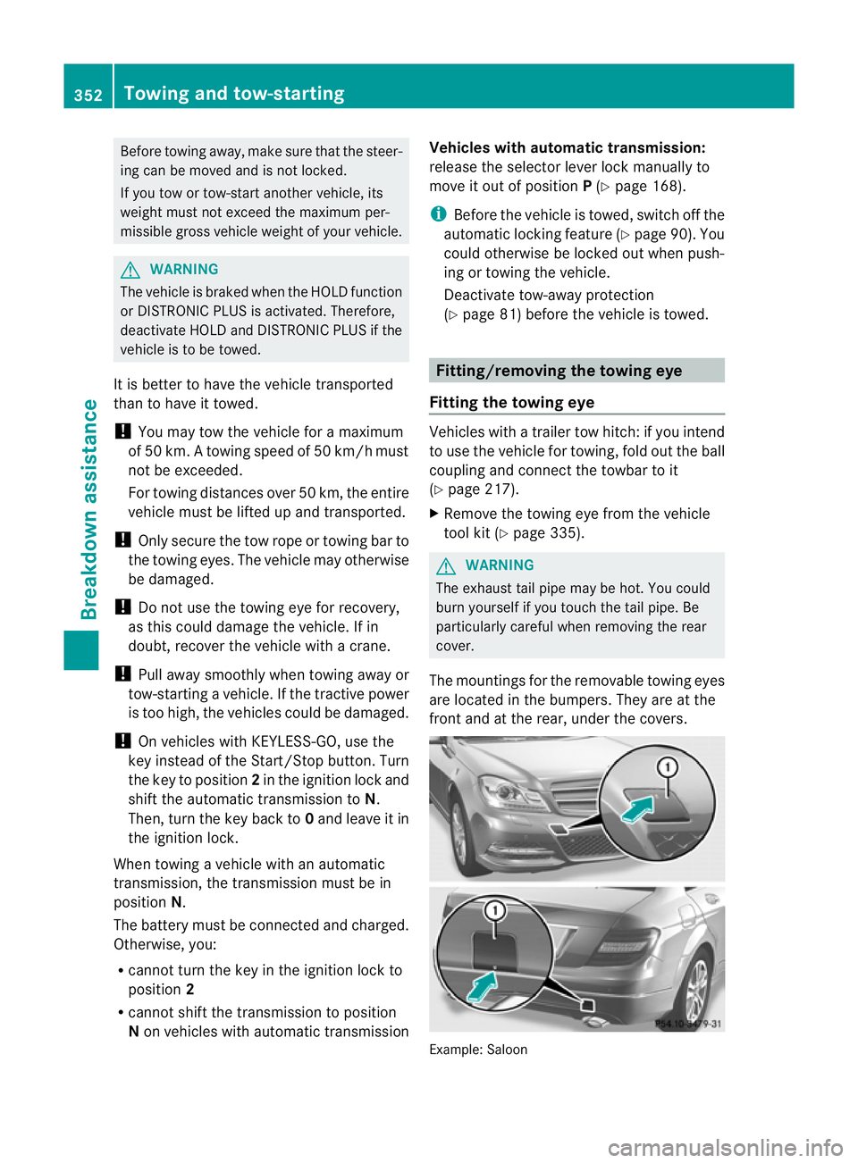
The mountings for the removable towing eyes
are located in the bumpers. They are at the
front and at the rear, under the covers. Example: Saloon352
Towing and tow-startingBreakdown assistance
Page 357 of 401
X
Vehicles with automatic transmission:
move the selector lever to P.
X Turn the key in the ignition lock to position
0and remove the key from the ignition
lock.
X Secure the vehicle.
! Only lash the vehicle dow nby the wheels
or wheel rims, no tby parts of the vehicle
such as axle or steering components. Oth-
erwise, the vehicle could be damaged. Notes for 4MATIC vehicles
! Vehicles with 4MATIC mus tnot be towed
with the front or rear axle raised; otherwise,
the transmission may be damaged.
If the vehicle has transmission damage or
damage to the front or rear axle, have it trans-
ported on a transporter or trailer.
In the event of damage to the electrical
system
If the battery is defective, the automatic
transmission will be locked in position P. To
shift the automatic transmission to position
N, you must provide power to the vehicle's
electrical system in the same way as when
jump-starting (Y page 350).
Have the vehicle transported on a transporter
or trailer. Tow-starting (emergency engine
starting)
When tow-starting, it is important that you
observe the safety instructions (Y page 351)
and the legal requirements in each respective
country.
! Vehicles with automatic transmission
must not be tow-started. The transmission
may otherwise be damaged. Before tow-starting the following conditions
must be fulfilled:
R
the battery is connected.
R the engine has cooled down.
R the catalytic converters have cooled down.
X Switch on the hazard warning lamps
(Y page 121).
X Fit the towing eye (Y page 352).
X Secure the rigid towing bar or the towing
rope.
X Depress and hold the brake pedal.
X Turn the key to position 2in the ignition
lock.
X Depress the clutch pedal and keep it
depressed.
X Shift to neutral.
X Release the brake pedal.
X Tow-start the vehicle.
X Engage second gear.
X Release the clutch pedal slowly; do not
operate the accelerator pedal while doing
so.
The engine is started.
X Depress the clutch pedal and shift to neu-
tral.
X Stop at a suitable place.
X Apply the parking brake.
X Remove the rigid towing bar or towing rope.
X Remove the towing eye (Y page 353).
X Switch off the hazard warning lamps. Electrical fuses
Important safety notes
The fuses in your vehicle serve to close down
faulty circuits. If afuse blows, all the compo-
nents on the circuit and their functions stop
operating. G
WARNING
Only use fuses that have been approved for
Mercedes-Ben zvehicles and which have the
correct fuse rating for the systems con- 354
Electrical fusesBreakdown assistance
Page 359 of 401
X
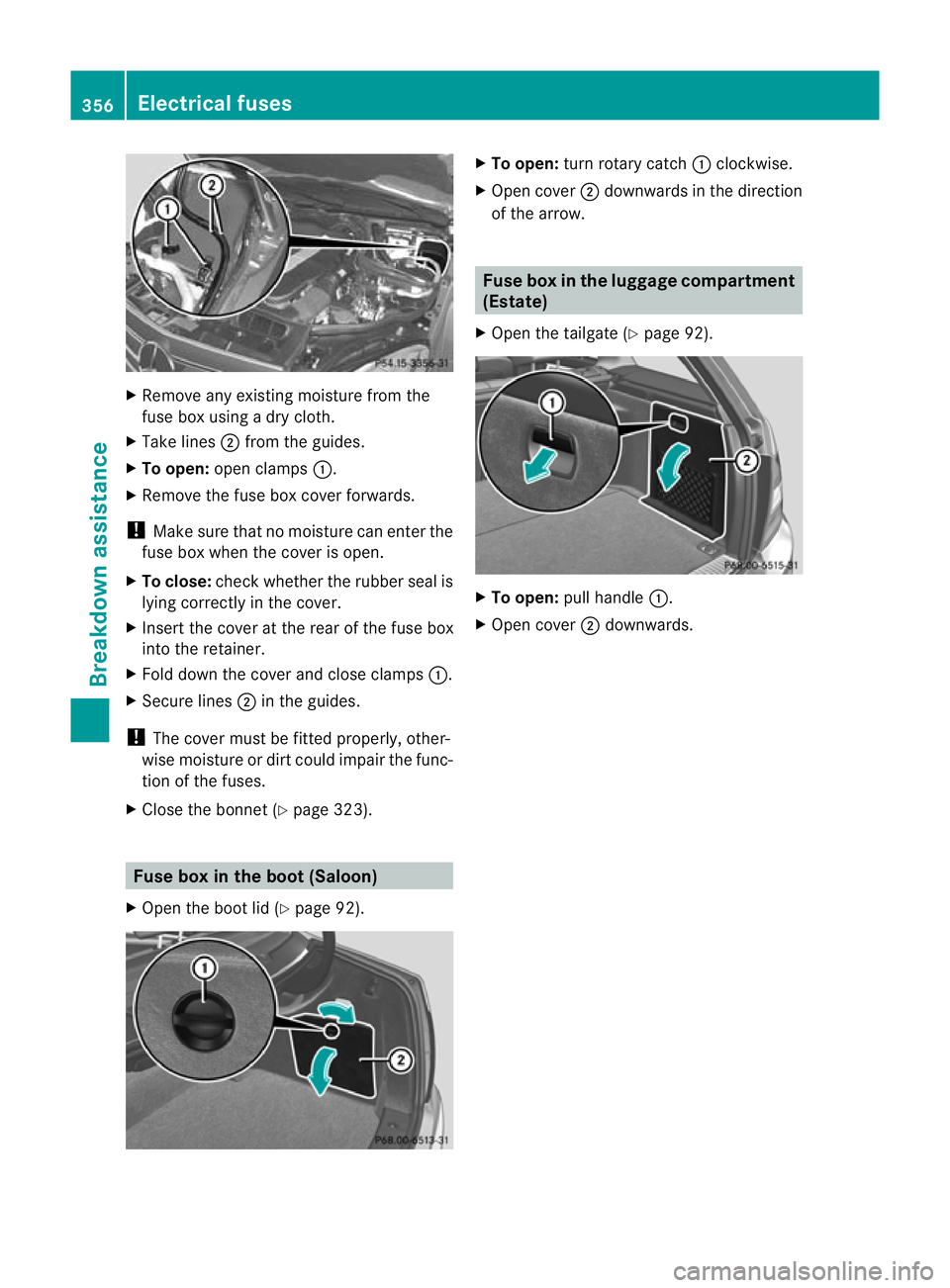
Remove any existing moisture from the
fuse box using a dry cloth.
X Take lines ;from the guides.
X To open: open clamps :.
X Remove the fuse box cover forwards.
! Make sure that no moisture can ente rthe
fuse box when the cover is open.
X To close: check whether the rubber seal is
lying correctly in the cover.
X Insert the cover at the rear of the fuse box
into the retainer.
X Fold down the cover and close clamps :.
X Secure lines ;in the guides.
! The cover must be fitted properly, other-
wise moisture or dirt could impair the func-
tion of the fuses.
X Close the bonnet (Y page 323).Fuse box in the boot (Saloon)
X Open the boot lid (Y page 92). X
To open: turn rotary catch :clockwise.
X Open cover ;downwards in the direction
of the arrow. Fuse box in the luggage compartment
(Estate)
X Open the tailgate (Y page 92). X
To open: pull handle :.
X Open cover ;downwards. 356
Electrical fusesBreakdown assistance