2011 MERCEDES-BENZ C-CLASS ESTATE ECU
[x] Cancel search: ECUPage 315 of 401
X
With your other hand, let the strap go slowly
until the load is secured.
X Make sure that locking button ?on brack-
ets Ais pressed.
This keeps brackets Ain place on the
loading rail.
X To remove: press release button =on
respective bracket Aand remove luggage
holder ;by pulling upwards and out.
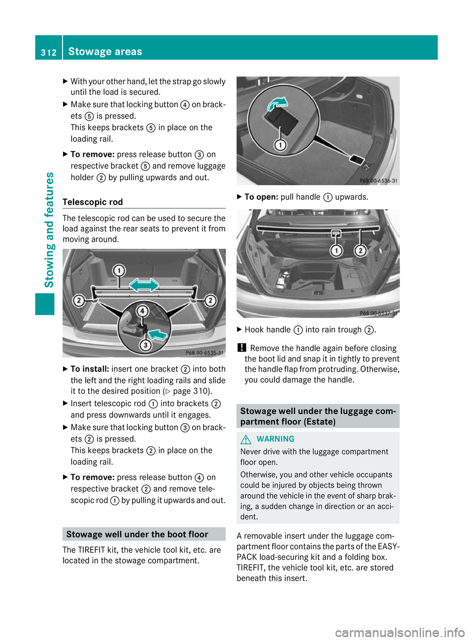
Telescopic rod The telescopic rod can be used to secure the
load against the rear seats to preven
titfrom
moving around. X
To install: insert one bracket ;into both
the left and the right loading rails and slide
it to the desired position (Y page 310).
X Insert telescopic rod :into brackets ;
and press downwards until it engages.
X Make sure that locking button =on brack-
ets ;is pressed.
This keeps brackets ;in place on the
loading rail.
X To remove: press release button ?on
respective bracket ;and remove tele-
scopic rod :by pulling it upwards and out. Stowage well under the bootf
loor
The TIREFIT kit, the vehicle tool kit ,etc. are
located in the stowage compartment. X
To open: pull handle :upwards. X
Hoo khandle :into rain trough ;.
! Remove the handle again before closing
the boot lid and snap it in tightly to prevent
the handle flap from protruding. Otherwise,
you could damage the handle. Stowage well under the luggage com-
partment floor (Estate)
G
WARNING
Never drive with the luggag ecompartment
floor open.
Otherwise, you and other vehicle occupants
could be injured by object sbeing thrown
around the vehicle in the event of sharp brak-
ing, a sudden change in direction or an acci-
dent.
Ar emovable insert under the luggage com-
partmen tfloor contains the parts of the EASY-
PACK load-securing kit and a folding box.
TIREFIT, the vehicle tool kit, etc. are stored
beneath this insert. 312
Stowage areasStowing and features
Page 316 of 401
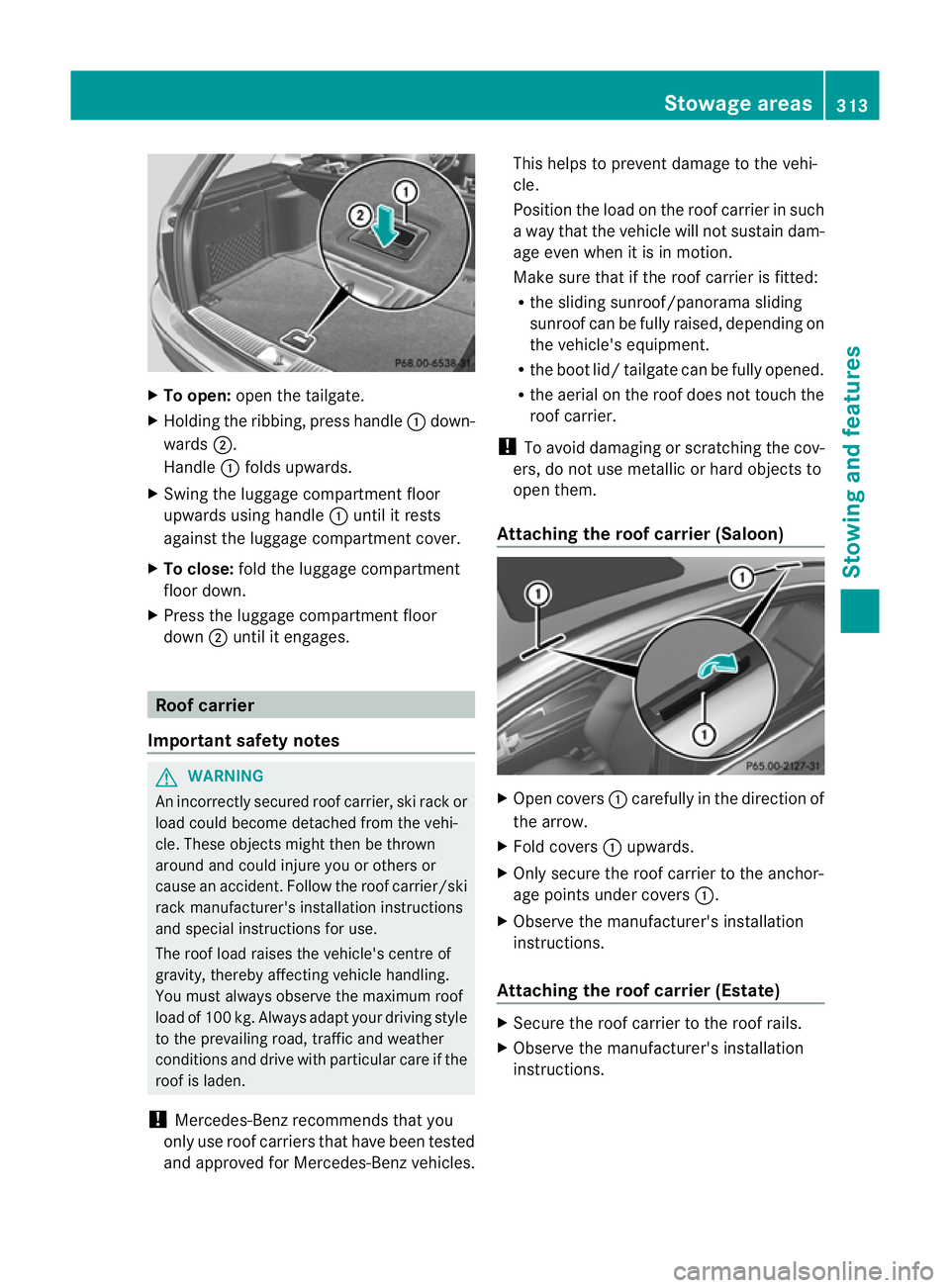
X
To open: open the tailgate.
X Holding the ribbing, press handle :down-
wards ;.
Handle :folds upwards.
X Swing the luggage compartment floor
upwards using handle :until it rests
against the luggage compartment cover.
X To close: fold the luggage compartment
floor down.
X Press the luggage compartment floor
down ;until it engages. Roof carrier
Important safety notes G
WARNING
An incorrectly secured roof carrier, ski rack or
load could become detached from the vehi-
cle .These objects might then be thrown
around and could injure you or others or
cause an accident. Follow the roof carrier/ski
rack manufacturer's installation instructions
and special instructions for use.
The roof load raises the vehicle's centre of
gravity, thereby affecting vehicle handling.
You must always observe the maximum roof
load of 100 kg. Always adapt your driving style
to the prevailing road, traffic and weather
conditions and drive with particular care if the
roof is laden.
! Mercedes-Ben zrecommends that you
only use roof carriers that have been tested
and approved for Mercedes-Benz vehicles. This helps to preven
tdamage to the vehi-
cle.
Positio nthe load on the roof carrier in such
a way that the vehicle will not sustain dam-
age even when it is in motion.
Make sure that if the roof carrier is fitted:
R the sliding sunroof/panorama sliding
sunroof can be fully raised, depending on
the vehicle's equipment.
R the boot lid/ tailgate can be fully opened.
R the aerial on the roof does not touch the
roof carrier.
! To avoid damaging or scratching the cov-
ers, do not use metallic or hard objects to
open them.
Attaching the roof carrier (Saloon) X
Open covers :carefully in the direction of
the arrow.
X Fold covers :upwards.
X Only secure the roof carrier to the anchor-
age points under covers :.
X Observe the manufacturer's installation
instructions.
Attaching the roof carrier (Estate) X
Secure the roof carrier to the roof rails.
X Observe the manufacturer's installation
instructions. Stowage areas
313Stowing and features Z
Page 322 of 401
More information on suitable mobile phones,
mobile phone brackets and on connecting
Bluetooth ®
capable mobile phones to Audio
20 or COMAND Online can be obtained:
R at your Mercedes-Benz Service Centre
R on the Internet at http://www.mercedes-
benz.com/connect
i The functions and services available when
you use the phone depend on your mobile
phone model and service provider.
Inserting the mobile phone X
Open the telephone compartment
(Y page 303).
X Place the mobile phone bracket into the
pre-installed bracket (see the separate
mobile phone bracket installation instruc-
tions).
X Insert the mobile phone into the mobile
phone bracket (see the separate mobile
phone bracket installation instructions).
If the mobile phone is inserted in the mobile
phone bracket, you can speak to the person
you are calling using the hands-free system.
i On some mobile phone brackets, you first
have to connect the mobile phone via Blue-
tooth ®
to a mobile phone bracket (see the
separate operating instructions for the
mobile phone bracket).
On these mobile phone brackets, the
mobile phone does not have to be inserted
into the bracket for you to be able to use
the telephone functions. In this case, the
charging function and aerial function are
not available.
Operating the mobile phone You can operate the telephone using the
6 and~ buttons on the luxury multi-
function steering wheel. You can operate
other mobile phone functions via the on-
board computer (Y page 235). If you take the key out of the ignition lock, the
mobile phone stays on but you can no longer
use the hands-free system.
If you are making a call and you would like to
take the key out of the ignition lock, first
remove the mobile phone from the bracket.
Otherwise, the call will be ended.
i When a mobile phone bracket is used that
is connected to the mobile phone via Blue-
tooth ®
: if you want to continue a call in
"Private mode", you have to perform the
necessary steps on the mobile phone (see
the separate mobile phone operating
instructions).
You can fold the pre-installed bracket up to
improve access to the stowage space
beneath it. Depending on the vehicle's equip-
ment, a USB connection and an AUX-IN con-
nection/Media Interface are fitted in the
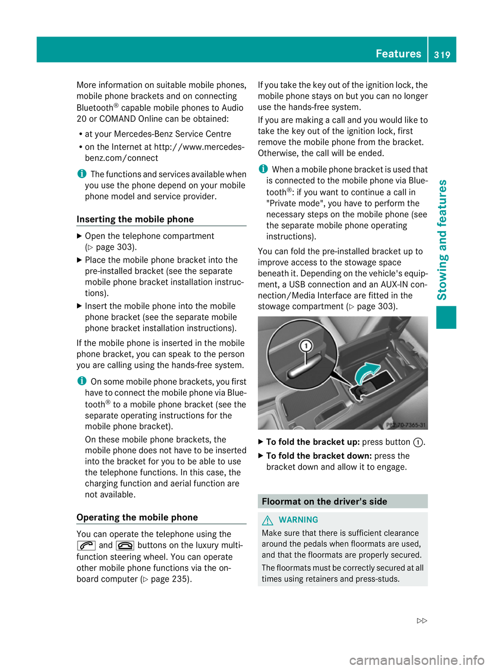
stowage compartmen t(Ypage 303). X
To fold the bracket up: press button:.
X To fold the bracket down: press the
bracket down and allow it to engage. Floormat on the driver's side
G
WARNING
Make sure that there is sufficient clearance
around the pedals when floormats are used,
and that the floormats are properly secured.
The floormats must be correctly secured at all
times using retainers and press-studs. Features
319Stowing and features
Z
Page 323 of 401
Before you drive off, check the floormats and
secure if necessary.
Afloormat which is not
properly secured can slip and, thereby, inter-
fere with the movemen tofthe pedals.
Do not place floormats on top of one another. X
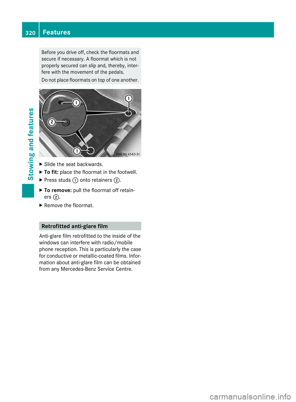
Slide the seat backwards.
X To fit: place the floormat in the footwell.
X Press studs :onto retainers ;.
X To remove: pull the floormat off retain-
ers ;.
X Remove the floormat. Retrofitted anti-glare film
Anti-glare film retrofitted to the inside of the
windows can interfere with radio/mobile
phone reception. This is particularly the case
for conductive or metallic-coated films. Infor-
mation about anti-glare film can be obtained
from any Mercedes-Benz Service Centre. 320
FeaturesStowing and features
Page 327 of 401
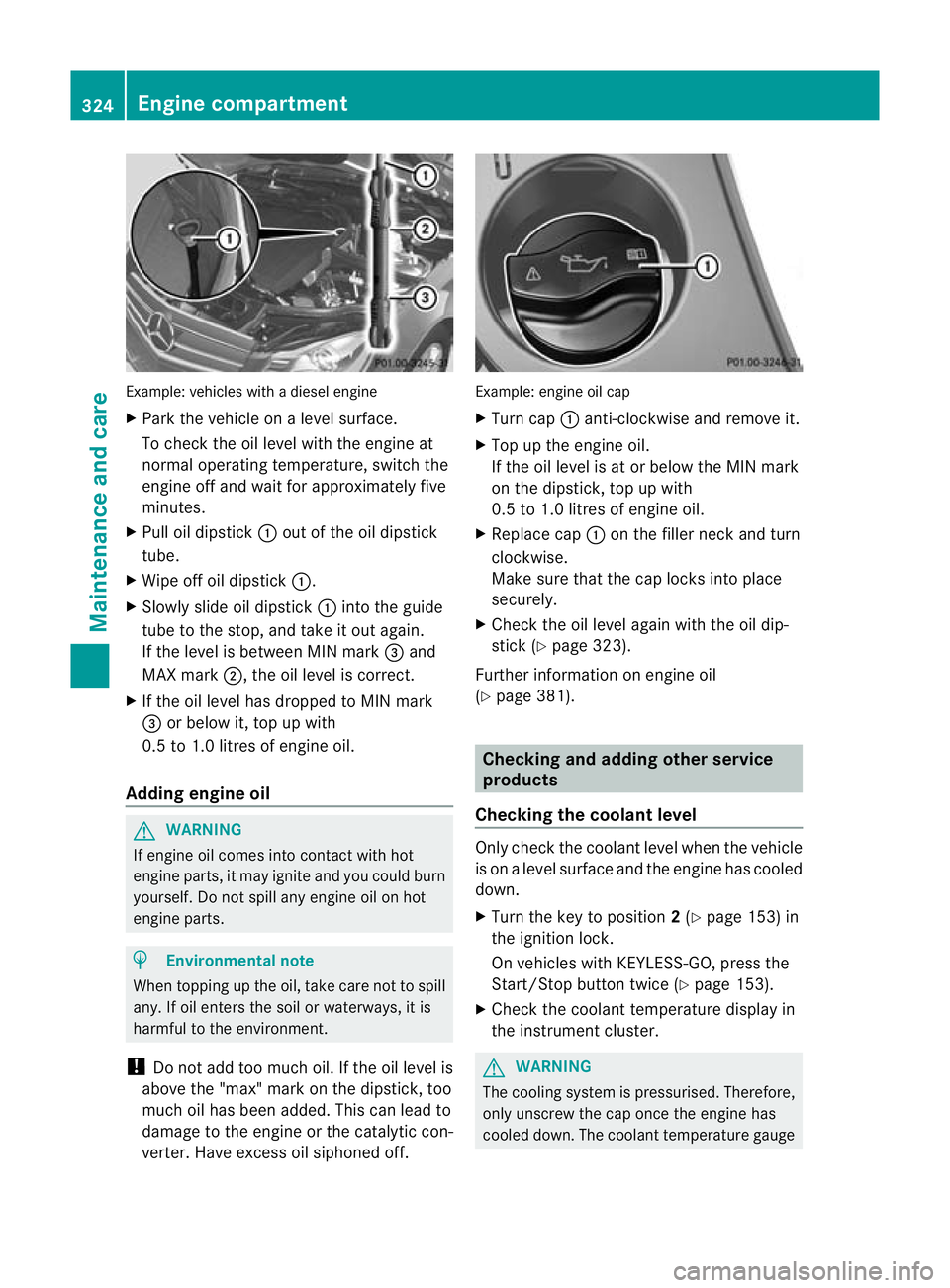
Example: vehicles with a diesel engine
X
Park the vehicle on a level surface.
To check the oil level with the engine at
normal operating temperature, switch the
engine off and wait for approximately five
minutes.
X Pull oil dipstick :outoft he oil dipstick
tube.
X Wipe off oil dipstick :.
X Slowly slide oil dipstick :into the guide
tube to the stop, and take it out again.
If the level is between MIN mark =and
MAX mark ;, the oil level is correct.
X If the oil level has dropped to MIN mark
= or below it, top up with
0.5 to 1.0 litres of engine oil.
Adding engine oil G
WARNING
If engine oil comes into contact with hot
engine parts, it may ignite and you could burn
yourself. Do not spill any engine oil on hot
engine parts. H
Environmental note
When topping up the oil, take care not to spill
any. If oil enters the soil or waterways, it is
harmful to the environment.
! Do not add too much oil. If the oil level is
above the "max" mark on the dipstick, too
much oil has been added. This can lead to
damage to the engine or the catalytic con-
verter. Have excess oil siphoned off. Example: engine oil cap
X
Turn cap :anti-clockwise and remove it.
X Top up the engine oil.
If the oil level is at or below the MIN mark
on the dipstick, top up with
0.5 to 1.0 litres of engine oil.
X Replace cap :on the filler neck and turn
clockwise.
Make sure that the cap locks into place
securely.
X Check the oil level again with the oil dip-
stick (Y page 323).
Further information on engine oil
(Y page 381). Checking and adding other service
products
Checking the coolant level Only check the coolant level when the vehicle
is on a level surface and the engine has cooled
down.
X Turn the key to position 2(Y page 153) in
the ignition lock.
On vehicles with KEYLESS-GO, press the
Start/Stop button twice (Y page 153).
X Check the coolant temperature display in
the instrument cluster. G
WARNING
The cooling system is pressurised. Therefore,
only unscrew the cap once the engine has
cooled down. The coolant temperature gauge 324
Engine compartmentMaintenance and care
Page 333 of 401
the windscree
northe wiper blades. On vehi-
cles with KEYLESS-GO, press the Start/Stop
button repeatedly until all indicator lamps in
the instrument cluster have gone off. The
windscreen wipers could otherwise move and
injure you.
! Only fold the windscreen wipers away
from the windscreen when vertical. Other-
wise, you will damage the bonnet.
! Do not pull on the wiper blade. Otherwise,
the wiper blade could be damaged.
! Do not clean wiper blades too often and
do not rub them too hard. Otherwise, the
graphite coating could be damaged. This
could cause wiper noise.
X Fold the wiper arms away from the wind-
screen.
X Cleant he wiper blades carefully using a
damp cloth.
X Fold the windscreen wipers back again
before switching on the ignition.
! Hold the wiper arm securely when folding
back. The windscreen could be damaged if
the wiper arm hits against it suddenly.
Cleaning the exterior lighting X
Cleant he plastic lenses of the exterior
lighting using a wet sponge and a mild
cleaning agent, e.g. Mercedes-Ben zcar
shampoo or cleaning cloths.
! Only use cleaning agents or cleaning
cloths that are suitable for plastic lenses.
Unsuitable cleaning agents or cleaning
cloths could scratch or damage the plastic
lenses of the exterior lighting. Cleaning the sensors
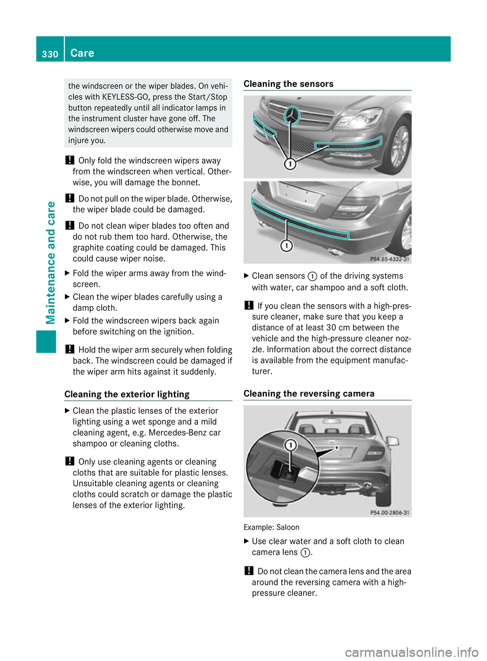
X
Clean sensors :of the driving systems
with water, car shampoo and a sof tcloth.
! If you clean the sensors with a high-pres-
sure cleaner, make sure that you keep a
distance of at least 30 cm between the
vehicle and the high-pressure cleaner noz-
zle. Information about the correct distance
is available fro mthe equipment manufac-
turer.
Cleaning the reversing camera Example: Saloon
X
Use clear water and a soft cloth to clean
camera lens :.
! Do not clean the camera lens and the area
around the reversing camera with a high-
pressure cleaner. 330
CareMaintenance and care
Page 337 of 401
Useful information
i This Owner's Manual describes all models
and all standard and optional equipment
available to your vehicle at the time of pub-
lication of the Owner's Manual. Country-
specific deviations are possible. Please
note that your vehicle may not be equipped
with all features described. This also
applies to safety-relevan tsystems and
functions.
i Please read the information on qualified
specialist workshops (Y page 28).Where will I find...?
Warning triangle
Removing the warning triangle Saloon:
the warning triangle is secured on
the inside of the boo tlid.
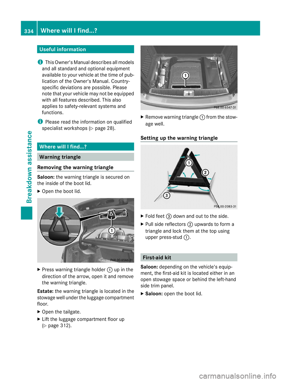
X Open the boot lid. X
Press warning triangle holder :up in the
direction of the arrow, open it and remove
the warning triangle.
Estate: the warning triangle is located in the
stowage well under the luggage compartment
floor.
X Open the tailgate.
X Lift the luggage compartmen tfloor up
(Y page 312). X
Remove warning triangle :fromt he stow-
age well.
Setting up the warning triangle X
Fold feet =down and out to the side.
X Pull side reflectors ;upwards to form a
triangle and lock them at the top using
upper press-stud :. First-aid kit
Saloon: depending on the vehicle's equip-
ment, the first-aid kit is located either in an
open stowage space or behind the left-hand
side trim panel.
X Saloon: open the boot lid. 334
Where will I find...?Breakdown assistance
Page 345 of 401
When using an emergency spare wheel you
must not exceed the maximum speed of
80 km/h.
G
WARNING
Have the emergency spare wheel/spare
wheel replaced with a new wheel as soon as
possible at a qualified specialist workshop
which has the necessary specialist knowledge
and tools to carry out the work required.
Mercedes-Benz recommends that you use a
Mercedes-Benz Service Centre for this pur-
pose. In particular, work relevant to safety or
on safety-related systems must be carried out
at a qualified specialist workshop.
i Vehicles without an emergency spare
wheel/spare wheel are not equipped with
wheel-changing tools at the factory. For
more information on which tools are
required to perform a wheel change on your
vehicle, e.g. wheel chock, wheel wrench or
centring pin, consult a Mercedes-Benz
Service Centre.
X Prepare the vehicle as described
(Y page 337).
X If a trailer is coupled to the vehicle, uncou-
ple it.
X Remove the following items (depending on
the vehicle's equipment) from the stowage
well under the boot/luggage compartment
floor:
R
the emergency spare wheel or spare
wheel
R the folding wheel chock
R the wheel wrench
R the jack
X Secure the vehicle to prevent it from rolling
away.
Securing the vehicle to prevent it from
rolling away If your vehicle is equipped with a wheel chock,
it can be found in the vehicle tool kit
(Y
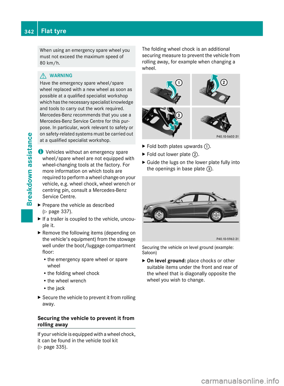
page 335). The folding wheel choc
kis an additional
securing measure to prevent the vehicle from
rolling away, for example when changing a
wheel. X
Fold both plates upwards :.
X Fold out lower plate ;.
X Guide the lugs on the lower plate fully into
the openings in base plate =. Securing the vehicle on level ground (example:
Saloon)
X
On level ground: place chocks or other
suitable items under the front and rear of
the wheel that is diagonally opposite the
wheel you wish to change. 342
Flat tyreBreakdown assistance