2011 MERCEDES-BENZ C-CLASS COUPE boot
[x] Cancel search: bootPage 290 of 373
X
Fold rea rseat backrest :back until it
engages. G
WARNING
Make sure that the rear seat backrest is cor-
rectly engaged. Otherwise, vehicle occupants
could be injured by objects being thrown
around if you:
R brake sharply
R change direction suddenly
R are involved in an accident
If the rear seat backrest is not engaged, this
will be shown in the multifunction display in
the instrument cluster.
i You should always engage the rear seat
backrests if you do not need the through-
loading feature. This will preven tunauthor-
ised access to the boot from the vehicle
interior.
X Move the driver's or front-passenger seat
back if necessary. Securing
aload
Lashing eyelets G
WARNING
Distribute the load on the lashing eyelets
evenly.
Otherwise, vehicle occupants could be
injured by objects being thrown around if you:
R brake sharply
R change directio nsuddenly
R are involved in an accident
Please observe the loading guidelines.
Observe the following notes on securing
loads:
R secure the load using the lashing eyelets.
R do no tuse elastic straps or nets to secure
a load, as these are only intended as an
anti-slip protection for light loads. R
do not route lashing materials across sharp
edges or corners.
R pad sharp edges for protection.
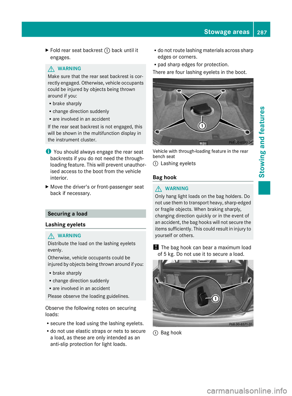
There are four lashing eyelets in the boot. Vehicle with through-loading feature in the rear
bench seat
:
Lashing eyelets
Bag hook G
WARNING
Only hang light loads on the bag holders. Do
not use them to transport heavy, sharp-edged
or fragile objects. When braking sharply,
changing direction quickly or in the event of
an accident, the bag hooks will not secure the
items sufficiently. This could result in injury to
yourselforo thers.
! The bag hoo kcan bear a maximum load
of 5 kg. Do not use it to secure a load. :
Bag hook Stowage areas
287Stowing and features Z
Page 291 of 373
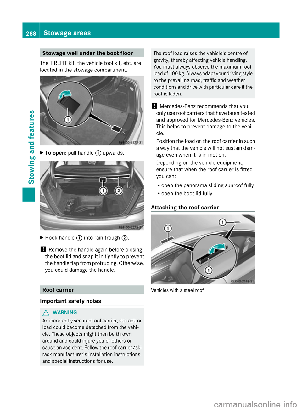
Stowage well under the boot floor
The TIREFIT kit, the vehicle tool kit, etc. are
located in the stowage compartment. X
To open: pull handle :upwards. X
Hook handle :into rain trough ;.
! Remove the handle again before closing
the boot lid and snap it in tightly to prevent
the handle flap from protruding. Otherwise,
you could damage the handle. Roof carrier
Important safety notes G
WARNING
An incorrectly secured roof carrier, ski rack or
load could become detached from the vehi-
cle. These objects might then be thrown
around and could injure you or others or
cause an accident. Follow the roof carrier/ski
rack manufacturer's installation instructions
and special instructions for use. The roof load raises the vehicle's centre of
gravity, thereby affecting vehicle handling.
You must always observe the maximum roof
load of 100 kg. Always adapt your driving style
to the prevailing road, traffic and weather
conditions and drive with particular care if the
roof is laden.
! Mercedes-Benz recommends that you
only use roof carriers that have been tested
and approved for Mercedes-Benz vehicles.
This helps to prevent damage to the vehi-
cle.
Position the load on the roof carrier in such
a way that the vehicle will not sustain dam-
age even when it is in motion.
Depending on the vehicle equipment,
ensure that when the roof carrier is fitted
you can:
R open the panorama sliding sunroof fully
R open the boot lid fully
Attaching the roof carrier Vehicles with a steel roof288
Stowage areasStowing and features
Page 317 of 373
Useful information
i This Owner's Manual describes all models
and all standard and optional equipment
available to your vehicle at the time of pub-
lication of the Owner's Manual. Country-
specific deviations are possible. Please
note that your vehicle may not be equipped
with all features described. This also
applies to safety-relevan tsystems and
functions.
i Please read the information on qualified
specialist workshops (Y page 26).Where will I find...?
Warning triangle
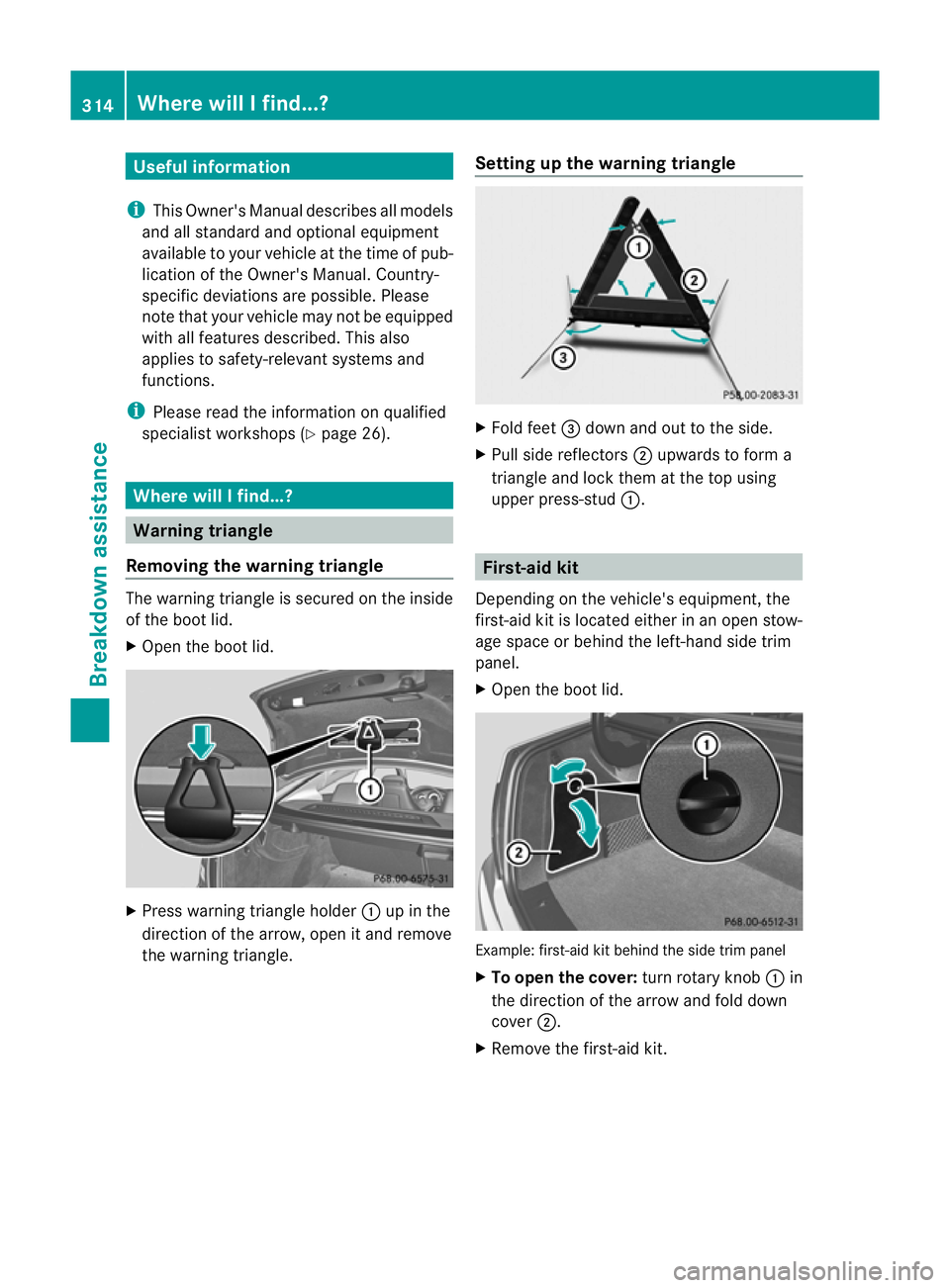
Removing the warning triangle The warning triangle is secured on the inside
of the boo tlid.
X Open the boot lid. X
Press warning triangle holder :up in the
direction of the arrow, open it and remove
the warning triangle. Setting up the warning triangle X
Fold feet =down and out to the side.
X Pull side reflectors ;upwards to form a
triangle and lock the matthe top using
upper press-stud :. First-aid kit
Depending on the vehicle's equipment, the
first-aid kit is located either in an open stow-
age space or behind the left-hand side trim
panel.
X Open the boot lid. Example: first-aid kit behind the side trim panel
X
To open the cover: turn rotary knob:in
the direction of the arrow and fold down
cover ;.
X Remove the first-aid kit. 314
Where will I find...?Breakdown assistance
Page 318 of 373
Example: first-aid kit in an open stowage space
X Remove first-aid kit :.
i Check the expiry date on the first-aid kit
at leas tonce a year .Replace the contents
if necessary, and replace missing contents. Fire extinguisher
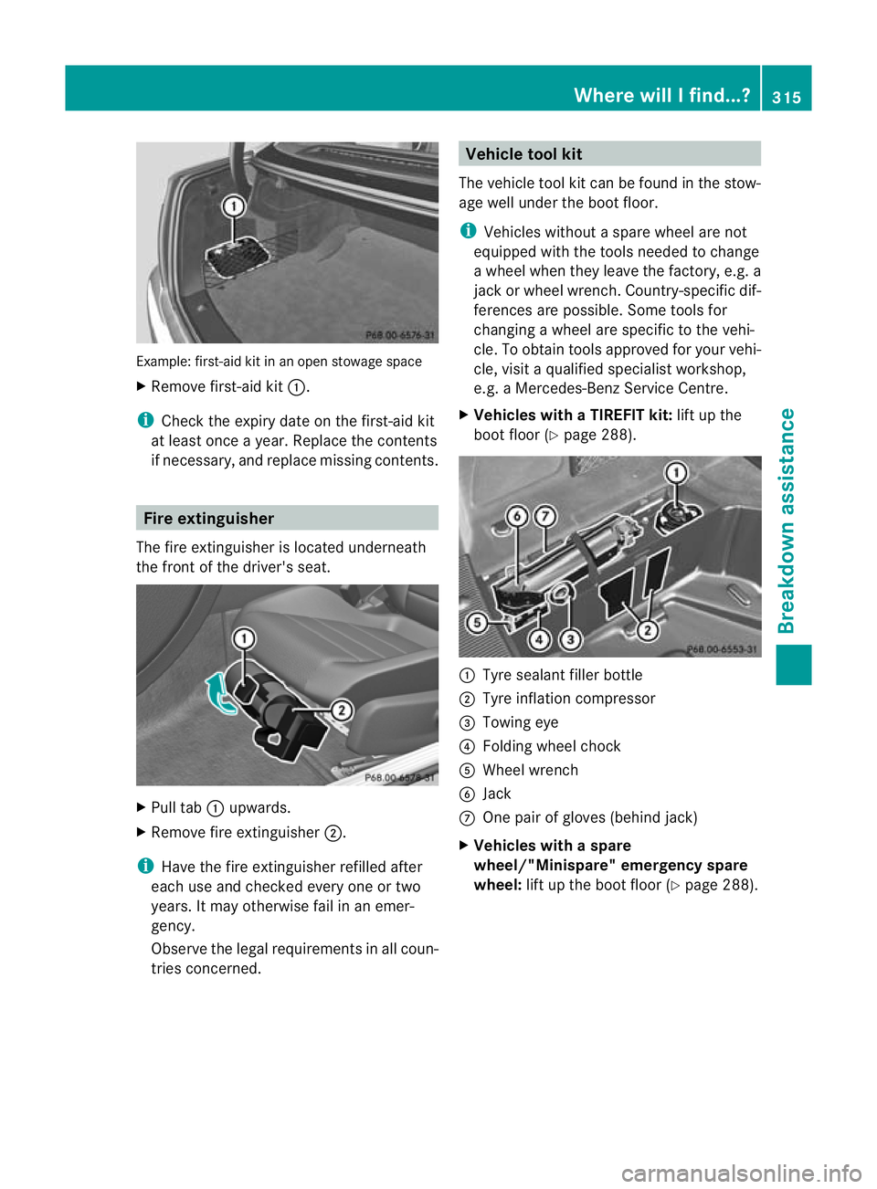
The fire extinguisher is located underneath
the front of the driver's seat. X
Pull tab :upwards.
X Remove fire extinguisher ;.
i Have the fire extinguisher refilled after
each use and checked every one or two
years. It may otherwise fail in an emer-
gency.
Observe the legal requirement sinall coun-
tries concerned. Vehicle tool kit
The vehicle tool kit can be found in the stow-
age well under the boot floor.
i Vehicles without a spare wheel are not
equipped with the tools needed to change
a wheel when they leave the factory, e.g. a
jac korw heel wrench. Country-specific dif-
ferences are possible. Some tools for
changing a wheel are specific to the vehi-
cle. To obtain tools approved for your vehi-
cle, visit a qualified specialist workshop,
e.g. a Mercedes-Benz Service Centre.
X Vehicles with a TIREFIT kit: lift up the
boot floor (Y page 288). :
Tyre sealant filler bottle
; Tyre inflation compressor
= Towing eye
? Folding wheel chock
A Wheel wrench
B Jack
C One pair of gloves (behind jack)
X Vehicles with a spare
wheel/"Minispare" emergency spare
wheel: lift up the boot floor (Y page 288). Where will I find...?
315Breakdown assistance
Page 319 of 373

:
Vehicle tool kit tray
; Stowage well
= Spare wheel/"Minispare" emergency
spare wheel
The vehicle tool kit contains:
R Foldable wheel chock
R Fuse allocation chart
R Jack
R One pair of gloves
R Wheel wrench
R Towing eye Spare wheel/"Minispare" emergency
spare wheel
The spare wheel or "Minispare" emergency
spare wheel can be found in the stowage well
under the boot floor.
X Lift the boot floor upwards (Y page 288). X
To remove the spare wheel or
"Minispare" emergencys pare wheel:
remove vehicle tool kit tray :.
X Turn stowage well ;anti-clockwise and
remove it.
X Remove the spare wheel or "Minispare"
emergency spare wheel =.
For further information on changing a wheel
and fitting the spare wheel, see
(Y page 321). Flat tyre
Preparing the vehicle
Your vehicle may be equipped with:
R a TIREFIT kit
R an emergency spare wheel
R MOExtended tyres (tyres with run-flat char-
acteristics) (Y page 324)
i Vehicle preparation is not necessary on
vehicles with MOExtended tyres.
i Vehicles with MOExtended tyres are not
equipped with a TIREFIT kit at the factory.
It is therefore recommended that you addi-
tionally equip your vehicle with a TIREFIT kit
if you fit tyres that do not feature run-flat
properties, e.g. winter tyres. A TIREFIT kit
can be obtained from a Mercedes-Benz
Service Centre.
X Stop the vehicle as far away as possible
from traffic on solid ,non-slippery and level
ground.
X Switch on the hazard warning lamps.
X Firmly depress the parking brake.
X Bring the front wheels into the straight-
ahead position.
X Vehicles with manual transmission:
engage first or reverse gear.
X Vehicles with automatic transmission:
move the selector lever to P.
X Switch off the engine. 316
Flat tyreBreakdown assistance
Page 324 of 373
The filler hose remains attached to the tyre
sealant bottle.
X Stow the tyre sealant bottle, the tyre infla-
tion compressor and the warning triangle.
X Drive to the nearest workshop and have the
tyre changed there.
X Have the tyre sealant bottle and the filler
hose replaced as soon as possible at a
qualified specialist workshop, e.g. at a
Mercedes-Benz Service Centre. H
Environmental note
Have the used tyre sealant bottle disposed of
professionally, e.g. at aMercedes-Benz
Service Centre.
X Have the tyre sealant bottle replaced every
four years at a qualified specialist work-
shop, e.g. a Mercedes-Benz Service
Centre. Changing
awheel and fitting the spare
wheel
Preparing the vehicle G
WARNING
The wheel and tyre size of the emergency
spare wheel/spare wheel may diffe rto that of
the damaged wheel. When using an emer-
gency spare wheel/spare wheel the handling
characteristics of the vehicle may change.
Adapt your style of driving accordingly.
Never operate the vehicle with more than one
emergency spare wheel/spare wheel that dif-
fers in size.
Only use an emergency spare wheel/spare
wheel of a differing size briefly and do not
switch off ESP ®
.
When using an emergency spare wheel you
must not exceed the maximum speed of
80 km/h. G
WARNING
Have the emergency spare wheel/spare
wheel replaced with a new wheel as soon as
possible at a qualified specialist workshop
which has the necessary specialist knowledge
and tools to carry out the work required.
Mercedes-Benz recommends that you use a
Mercedes-Benz Service Centre for this pur-
pose. In particular, work relevant to safety or
on safety-related systems must be carried out
at a qualified specialist workshop.
i Vehicles without an emergency spare
wheel/spare wheel are not equipped with
wheel-changing tools at the factory. For
more information on which tools are
required to perform a wheel change on your
vehicle, e.g. wheel chock, wheel wrench or
centring pin, consult a Mercedes-Benz
Service Centre.
X Prepare the vehicle as described
(Y page 316).
X If a trailer is coupled to the vehicle, uncou-
ple it.
X Remove the following items (depending on
the vehicle's equipment) from the stowage
well under the boot floor:
R
the emergency spare wheel or spare
wheel
R the folding wheel chock
R the wheel wrench
R the jack
X Secure the vehicle to prevent it from rolling
away.
Securing the vehicle to prevent it from
rolling away If your vehicle is equipped with a wheel chock,
it can be found in the vehicle tool kit
(Y
page 315).
The folding wheel chock is an additional
securing measure to prevent the vehicle from
rolling away, for example when changing a
wheel. Flat tyre
321Breakdown assistance Z
Page 325 of 373

X
Fold both plates upwards :.
X Fold ou tlower plate ;.
X Guide the lugs on the lower plate fully into
the openings in base plate =.Securing the vehicle on level ground
X
On level ground: place chocks or other
suitable items under the front and rear of
the wheel that is diagonally opposite the
wheel you wish to change. Securing the vehicle on slight downhill gradients
X
On downhill gradients: place chocks or
other suitable items in front of the wheels
of the front and rear axle. Raising the vehicle G
WARNING
The jack is intended only for lifting the vehicle
briefly for wheel changes.
The vehicle must be placed on stands if you
intend to work under it.
Make sure that the jack is placed on a firm,
non-slip, level surface. Do not use wooden
blocks or similar objects as a jack underlay.
The vehicle could otherwise slip off the jack
and seriously injure you.
Do not start the engine at any time while the
wheel is being changed.
Do not lie under the vehicle when it is being
supported by the jack.Ify ou do not raise the
vehicle as described, it could slip off the jack
(e.g. if the engine is started or a door or the
boot lid is opened or closed) and seriously
injure you. G
WARNING
If you fail to position the jack correctly, the
vehicle may:
R slip off the jack
R injure you or others
R be damaged.
Therefore, make sure that the jack is posi-
tioned correctly in the respective jacking
points. Before positioning the jack, remove
any dirt that may have collected in the jacking
points. Please note that you must position the
jack in the opening of the jacking point. 322
Flat tyreBreakdown assistance
Page 327 of 373

Do not tighte
nthe wheel bolts completely
while the vehicle is still jacked up. The vehicle
could topple off the jack.
X Cleant he wheel and wheel hub contact
surfaces. X
Slide the emergency spare wheel/spare
wheel onto the wheel hub and push it on.
X Tighten the wheel bolts until they are fin-
ger-tight.
Lowering the vehicle X
Turn the crank of the jack anti-clockwise
until the vehicle is once again standing
firmly on the ground.
X Place the jack to one side. X
Tighten the wheel bolts evenly in a cross-
wise pattern in the sequence indicated
(: toA ). The tightening torque must be
130 Nm. G
WARNING
Have the tightening torque checked immedi-
ately after a wheel is changed. The wheels
could work loose if they are not tightened to
a torque of 130 Nm.
X Turn the jack back to its initial position and
store it together with the rest of the vehicle
tool kit in the stowage well under the boot
floor.
X Transport the faulty wheel in the boot.
or
X Depending on the size of the wheel, you
may also be able to secure the faulty wheel
in the spare wheel well. In this case, you
will have to remove the stowage tray from
the spare wheel well and stow it securely
in the boot.
i When you are driving with the emergency
spare wheel fitted, the tyre pressure loss
warning system cannot function reliably.
Only restart the tyre pressure loss warning
system when the defective wheel has been
replaced with a new wheel. MOExtended tyres (tyres with run-flat
characteristics)
MOExtended tyres (tyres with run-flat char-
acteristics) allow you to continue driving the
vehicle even when one or more tyres lose all
air pressure.
MOExtended tyres may only be used in con-
junction with the activated tyre pressure loss
warning system or with the tyre pressure
monitor.
The maximum permissible distance which
can be driven in run-flat mode depends on the
load in the vehicle. It is 80 km if the vehicle
is partially laden and 30 km if fully laden.
The maximum permissible distance which
can be driven in run-flat mode is counted from
the moment the tyre pressure loss warning
appears in the multifunction display. 324
Flat tyreBreakdown assistance