Page 195 of 306
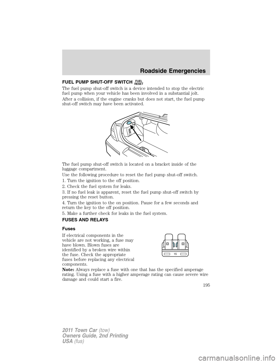
FUEL PUMP SHUT-OFF SWITCHFUEL
RESET
The fuel pump shut-off switch is a device intended to stop the electric
fuel pump when your vehicle has been involved in a substantial jolt.
After a collision, if the engine cranks but does not start, the fuel pump
shut-off switch may have been activated.
The fuel pump shut-off switch is located on a bracket inside of the
luggage compartment.
Use the following procedure to reset the fuel pump shut-off switch.
1. Turn the ignition to the off position.
2. Check the fuel system for leaks.
3. If no fuel leak is apparent, reset the fuel pump shut-off switch by
pressing the reset button.
4. Turn the ignition to the on position. Pause for a few seconds and
return the key to the off position.
5. Make a further check for leaks in the fuel system.
FUSES AND RELAYS
Fuses
If electrical components in the
vehicle are not working, a fuse may
have blown. Blown fuses are
identified by a broken wire within
the fuse. Check the appropriate
fuses before replacing any electrical
components.
Note:Always replace a fuse with one that has the specified amperage
rating. Using a fuse with a higher amperage rating can cause severe wire
damage and could start a fire.
15
Roadside Emergencies
195
2011 Town Car(tow)
Owners Guide, 2nd Printing
USA(fus)
Page 199 of 306
Fuse/Relay
LocationFuse Amp
RatingProtected Circuits
26 15A LCM (Park lamps, cornering
lamps, license lamps)
27 — Not used
28 7.5A Brake signal, LCM (BTSI), ABS
29 — Not used
30 — Not used
31 5A LCM (Key in)
32 7.5A Delay accessory (audio)
33 — Not used
K101 — Delayed accessory
Power distribution box
The power distribution box is located in the engine compartment. The
power distribution box contains high-current fuses that protect your
vehicle’s main electrical systems from overloads.
WARNING:Always disconnect the battery before servicing high
current fuses.
WARNING:To reduce risk of electrical shock, always replace
the cover to the power distribution box before reconnecting the
battery or refilling fluid reservoirs.
If the battery has been disconnected and reconnected, refer to the
Batterysection of theMaintenance and Specificationschapter.
Roadside Emergencies
199
2011 Town Car(tow)
Owners Guide, 2nd Printing
USA(fus)
Page 205 of 306
Full-size matching spare tire/wheel information
This spare tire/wheel will match the road tire/wheel. When driving with
the full size matching spare tire/wheel, do not exceed 70 mph
(113 km/h). It is intended for temporary use only. This means if you
need to use it, you should replace it as soon as possible.
Stopping and securing the vehicle
1. Park on a level surface, activate
hazard flashers and set parking
brake.
2. Place gearshift lever in P (Park)
and turn engine off.
Removing the spare tire and jack
Mini-spare
1. Remove the carpeted wheel cover
located on the right-hand side, next
to the wheel well.
2. Remove the wing nut/bolt
assembly that secures the spare tire
and jack by turning it
counterclockwise.
HOOD
Roadside Emergencies
205
2011 Town Car(tow)
Owners Guide, 2nd Printing
USA(fus)
Page 210 of 306
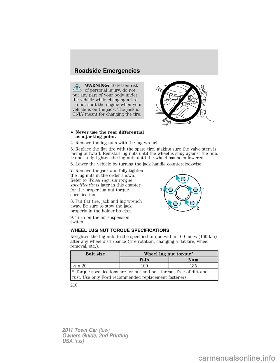
WARNING:To lessen risk
of personal injury, do not
put any part of your body under
the vehicle while changing a tire.
Do not start the engine when your
vehicle is on the jack. The jack is
ONLY meant for changing the tire.
•Never use the rear differential
as a jacking point.
4. Remove the lug nuts with the lug wrench.
5. Replace the flat tire with the spare tire, making sure the valve stem is
facing outward. Reinstall lug nuts until the wheel is snug against the hub.
Do not fully tighten the lug nuts until the wheel has been lowered.
6. Lower the vehicle by turning the jack handle counterclockwise.
7. Remove the jack and fully tighten
the lug nuts in the order shown.
Refer toWheel lug nut torque
specificationslater in this chapter
for the proper lug nut torque
specification.
8. Put flat tire, jack and lug wrench
away. Be sure to stow the jack
properly in the holder bracket.
9. Turn on the air suspension
switch.
WHEEL LUG NUT TORQUE SPECIFICATIONS
Retighten the lug nuts to the specified torque within 100 miles (160 km)
after any wheel disturbance (tire rotation, changing a flat tire, wheel
removal, etc.).
Bolt size Wheel lug nut torque*
ft-lb N•m
1�2x 20 100 135
* Torque specifications are for nut and bolt threads free of dirt and
rust. Use only Ford recommended replacement fasteners.
1
4 3
2 5
Roadside Emergencies
210
2011 Town Car(tow)
Owners Guide, 2nd Printing
USA(fus)
Page 212 of 306
Preparing your vehicle
When the battery is disconnected or a new battery is installed, the
automatic transmission must relearn its shift strategy. As a result, the
transmission may have firm and/or soft shifts. This operation is
considered normal and will not affect function or durability of the
transmission. Over time, the adaptive learning process will fully update
transmission operation.
1.Use only a 12–volt supply to start your vehicle.
2. Do not disconnect the battery of the disabled vehicle as this could
damage the vehicle’s electrical system.
3. Park the booster vehicle close to the hood of the disabled vehicle
making sure the two vehiclesdo nottouch. Set the parking brake on
both vehicles and stay clear of the engine cooling fan and other moving
parts.
4. Check all battery terminals and remove any excessive corrosion before
you attach the battery cables. Ensure that vent caps are tight and level.
5. Turn the heater fan on in both vehicles to protect from any electrical
surges. Turn all other accessories off.
Connecting the jumper cables
Note:In the illustration, the vehicle on the bottom is used to designate
the assisting (boosting) battery.
Roadside Emergencies
212
2011 Town Car(tow)
Owners Guide, 2nd Printing
USA(fus)
Page 213 of 306
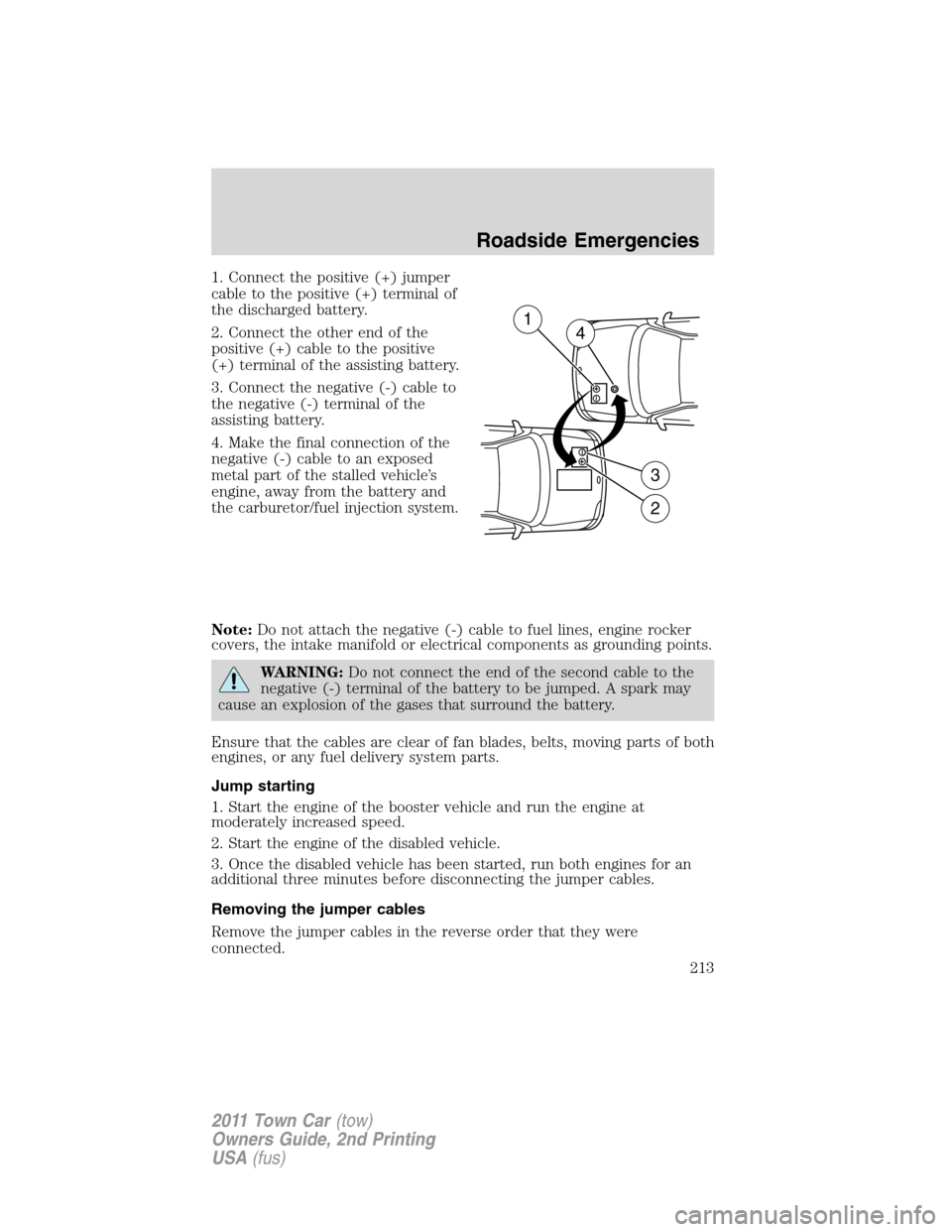
1. Connect the positive (+) jumper
cable to the positive (+) terminal of
the discharged battery.
2. Connect the other end of the
positive (+) cable to the positive
(+) terminal of the assisting battery.
3. Connect the negative (-) cable to
the negative (-) terminal of the
assisting battery.
4. Make the final connection of the
negative (-) cable to an exposed
metal part of the stalled vehicle’s
engine, away from the battery and
the carburetor/fuel injection system.
Note:Do not attach the negative (-) cable to fuel lines, engine rocker
covers, the intake manifold or electrical components as grounding points.
WARNING:Do not connect the end of the second cable to the
negative (-) terminal of the battery to be jumped. A spark may
cause an explosion of the gases that surround the battery.
Ensure that the cables are clear of fan blades, belts, moving parts of both
engines, or any fuel delivery system parts.
Jump starting
1. Start the engine of the booster vehicle and run the engine at
moderately increased speed.
2. Start the engine of the disabled vehicle.
3. Once the disabled vehicle has been started, run both engines for an
additional three minutes before disconnecting the jumper cables.
Removing the jumper cables
Remove the jumper cables in the reverse order that they were
connected.
+–
+–
2
3
14
Roadside Emergencies
213
2011 Town Car(tow)
Owners Guide, 2nd Printing
USA(fus)
Page 214 of 306
Note:In the illustration, the vehicle on the bottom is used to designate
the assisting (boosting) battery.
1. Remove the jumper cable from
the ground metal surface.
2. Remove the jumper cable on the
negative (-) terminal of the booster
vehicle’s battery.
3. Remove the jumper cable from
the positive (+) terminal of the
booster vehicle’s battery.
4. Remove the jumper cable from
the positive (+) terminal of the
disabled vehicle’s battery.
After the disabled vehicle has been started and the jumper cables
removed, allow it to idle for several minutes so the engine computer can
relearn its idle conditions.
+–
+–
DA
B
C
4D1
2
3
Roadside Emergencies
214
2011 Town Car(tow)
Owners Guide, 2nd Printing
USA(fus)
Page 222 of 306
The use of leaded fuel in your vehicle without proper conversion may
damage the effectiveness of your emission control system and may cause
engine knocking or serious engine damage. Ford Motor Company/Ford of
Canada is not responsible for any damage caused by use of improper
fuel. Using leaded fuel may also result in difficulty importing your vehicle
back into the U.S.
If your vehicle must be serviced while you are traveling or living in
Asia-Pacific Region, Sub-Saharan Africa, U.S. Virgin Islands, Central
America, the Caribbean, and Israel, contact the nearest authorized
dealer. If the authorized dealer cannot help you, contact:
FORD MOTOR COMPANY
FORD EXPORT OPERATIONS & GLOBAL INITIATIVES
1555 Fairlane Drive
Fairlane Business Park #3
Allen Park, Michigan 48101
U.S.A.
Telephone: (313) 594-4857
For customers in Guam, the Commonwealth of the Northern Mariana
Islands (CNMI), America Samoa, and the U.S. Virgin Islands, please feel
free to call our Toll-Free Number: (800) 841-FORD (3673).
FAX: (313) 390-0804
Email: [email protected]
If your vehicle must be serviced while you are traveling or living in
Puerto Rico, contact the nearest authorized dealer. If the authorized
dealer cannot help you, contact:
Ford International Business Development Inc.
Customer Relationship Center
P.O. Box 11957
Caparra Heights Station
San Juan, Puerto Rico 00922-1957
Telephone: (800) 841-FORD (3673)
FAX: (313) 390-0804
Email: [email protected]
www.ford.com.pr
Customer Assistance
222
2011 Town Car(tow)
Owners Guide, 2nd Printing
USA(fus)