2011 INFINITI QX56 horn
[x] Cancel search: hornPage 4761 of 5598
![INFINITI QX56 2011 Factory Service Manual
SEC-154
< SYMPTOM DIAGNOSIS >[WITH INTELLIGENT KEY SYSTEM]
PANIC ALARM FUNCTION DOES NOT OPERATE
PANIC ALARM FUNCTION
DOES NOT OPERATE
DescriptionINFOID:0000000006226336
NOTE:
Before performing th INFINITI QX56 2011 Factory Service Manual
SEC-154
< SYMPTOM DIAGNOSIS >[WITH INTELLIGENT KEY SYSTEM]
PANIC ALARM FUNCTION DOES NOT OPERATE
PANIC ALARM FUNCTION
DOES NOT OPERATE
DescriptionINFOID:0000000006226336
NOTE:
Before performing th](/manual-img/42/57033/w960_57033-4760.png)
SEC-154
< SYMPTOM DIAGNOSIS >[WITH INTELLIGENT KEY SYSTEM]
PANIC ALARM FUNCTION DOES NOT OPERATE
PANIC ALARM FUNCTION
DOES NOT OPERATE
DescriptionINFOID:0000000006226336
NOTE:
Before performing the diagnosis following procedure, check “Work Flow”. Refer to SEC-48, "
Work Flow".
Check that vehicle is under the condition shown in “Conditions of vehicle” before starting diagnosis, and
check each symptom.
CONDITIONS OF VEHICLE (OPERATION CONDITIONS)
Ignition switch is in OFF or LOCK position.
Intelligent Key is removed from key slot.
Diagnosis ProcedureINFOID:0000000006226337
1.CHECK REMOTE KEYL ESS ENTRY FUNCTION
Check remote keyless entry function.
Does door lock/unlock with Intelligent key button?
YES >> GO TO 2.
NO >> Go to DLK-175, "
Diagnosis Procedure".
2.CHECK VEHICLE SECURITY ALARM OPERATION
Check vehicle security alarm operation.
Does alarm (headlamps and horns) active?
YES >> GO TO 3.
NO >> Go to SEC-18, "
VEHICLE SECURITY SYSTEM : System Description".
3.CHECK “PANIC ALARM SET” SETTING IN “WORK SUPPORT”
Check “PANIC ALARM SET” setting in “WORK SUPPORT”.
Refer to SEC-22, "
INTELLIGENT KEY : CONSULT-III F unction (BCM - INTELLIGENT KEY)".
Is the inspection result normal?
YES >> GO TO 4.
NO >> Set “PANIC ALARM SET” setting in “WORK SUPPORT”.
4.CONFIRM THE OPERATION
Confirm the operation again.
Is the result normal?
YES >> Check intermittent incident. Refer to GI-40, "Intermittent Incident".
NO >> GO TO 1.
Revision: 2010 May2011 QX56
Page 5457 of 5598
COMPONENT PARTSWT-7
< SYSTEM DESCRIPTION >
C
DF
G H
I
J
K L
M A
B
WT
N
O P
Component DescriptionINFOID:0000000006225489
*: Mainly used for the tire inflation function.
Low Tire Pressure Warning Control UnitINFOID:0000000006225490
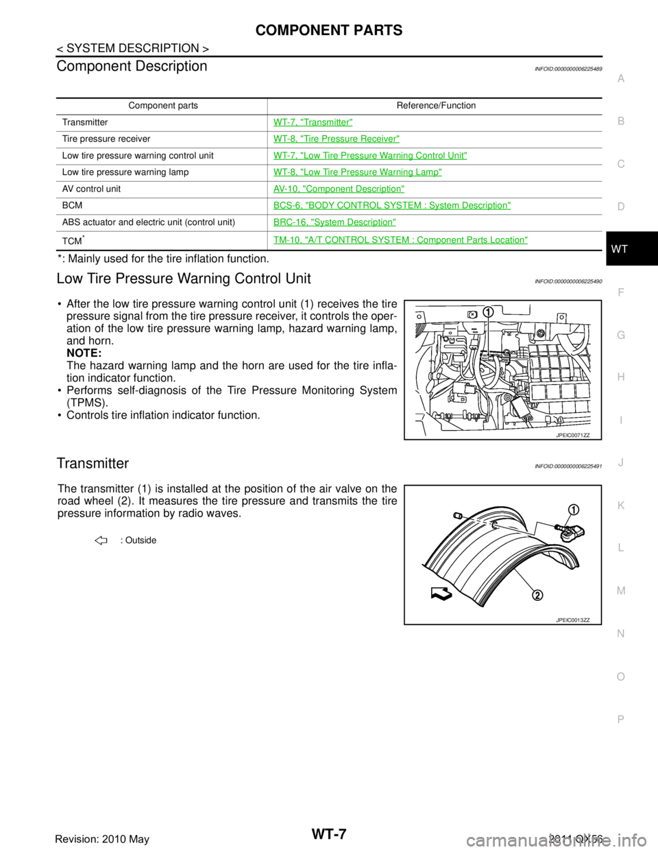
After the low tire pressure warning control unit (1) receives the tire pressure signal from the tire pressure receiver, it controls the oper-
ation of the low tire pressure warning lamp, hazard warning lamp,
and horn.
NOTE:
The hazard warning lamp and the horn are used for the tire infla-
tion indicator function.
Performs self-diagnosis of the Tire Pressure Monitoring System
(TPMS).
Controls tire inflation indicator function.
TransmitterINFOID:0000000006225491
The transmitter (1) is installed at the position of the air valve on the
road wheel (2). It measures the ti re pressure and transmits the tire
pressure information by radio waves.
Component parts Reference/Function
Transmitter WT-7, "
Transmitter"
Tire pressure receiverWT-8, "Tire Pressure Receiver"
Low tire pressure warning control unit WT-7, "Low Tire Pressure Warning Control Unit"
Low tire pressure warning lamp WT-8, "Low Tire Pressure Warning Lamp"
AV control unit AV- 1 0 , "Component Description"
BCMBCS-6, "BODY CONTROL SYSTEM : System Description"
ABS actuator and electric unit (control unit)BRC-16, "System Description"
TCM*TM-10, "A/T CONTROL SYSTEM : Component Parts Location"
JPEIC0071ZZ
: Outside
JPEIC0013ZZ
Revision: 2010 May2011 QX56
Page 5459 of 5598
SYSTEMWT-9
< SYSTEM DESCRIPTION >
C
DF
G H
I
J
K L
M A
B
WT
N
O P
SYSTEM
System DescriptionINFOID:0000000006225494
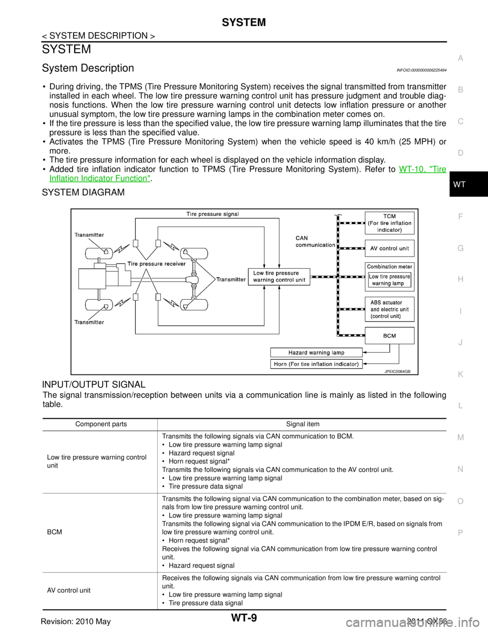
During driving, the TPMS (Tire Pressure Monitoring System) receives the signal transmitted from transmitter
installed in each wheel. The low tire pressure warning control unit has pressure judgment and trouble diag-
nosis functions. When the low tire pressure warning control unit detects low inflation pressure or another
unusual symptom, the low tire pressure warning lamps in the combination meter comes on.
If the tire pressure is less than the specified value, t he low tire pressure warning lamp illuminates that the tire
pressure is less than the specified value.
Activates the TPMS (Tire Pressure Monitoring Sy stem) when the vehicle speed is 40 km/h (25 MPH) or
more.
The tire pressure information for each wheel is displayed on the vehicle information display.
Added tire inflation indicator function to TPMS (Tire Pressure Monitoring System). Refer to WT-10, "
Tire
Inflation Indicator Function".
SYSTEM DIAGRAM
INPUT/OUTPUT SIGNAL
The signal transmission/reception between units via a comm unication line is mainly as listed in the following
table.
JPEIC0084GB
Component parts Signal item
Low tire pressure warning control
unit Transmits the following signals via CAN communication to BCM.
Low tire pressure
warning lamp signal
Hazard request signal
Horn request signal*
Transmits the following signals via CAN communication to the AV control unit.
Low tire pressure warning lamp signal
Tire pressure data signal
BCM Transmits the following signal via CAN communication to the combination meter, based on sig-
nals from low tire pressure warning control unit.
Low tire pressure
warning lamp signal
Transmits the following signal via CAN communication to the IPDM E/R, based on signals from
low tire pressure wa rning control unit.
Horn request signal*
Receives the following signal via CAN communication from low tire pressure warning control
unit.
Hazard request signal
AV control unit Receives the following signals via CAN communication from low tire pressure warning control
unit.
Low tire pressure
warning lamp signal
Tire pressure data signal
Revision: 2010 May2011 QX56
Page 5460 of 5598
WT-10
< SYSTEM DESCRIPTION >
SYSTEM
*: Mainly used for the tire inflation indicator function.
LOW TIRE PRESSURE WARNING LAMP CONTROL CONDITION
Uses CAN communication from the low tire pressure warning control unit to illuminate the low tire pressure
warning lamp on the combination meter.
*: Tire pressure at each condition differs.
HAZARD WARNING LAMP CONTROL CONDITION
The low tire pressure warning control unit transmits a hazard request signal to BCM. BCM blinks the hazard
warning lamp, according to the signal.
The hazard warning lamp blinks under the following conditions.
Condition of Blinking The Hazard Warning Lamp When wake-up of registered wheel has been completed. Refer to WT-28, "Work Procedure".
When ID registration is completed. Refer to WT-29, "
Work Procedure".
During the use of the tire inflation indicator function.
HORN CONTROL CONDITION
The low tire pressure warning control unit transmits a horn request signal to BCM. BCM controls horn sound,
according to the signal.
The horn sounds under the following condition.
Condition of Sounding Horn During the use of tire inflation indicator function.
Tire Inflation Indicator FunctionINFOID:0000000006225495
This function operates only when the A/T shift selector position is in P-range with the ignition switch ON or
with the engine started.
NOTE:
The tire inflation indicator function is recommended to use with the engine stopped.
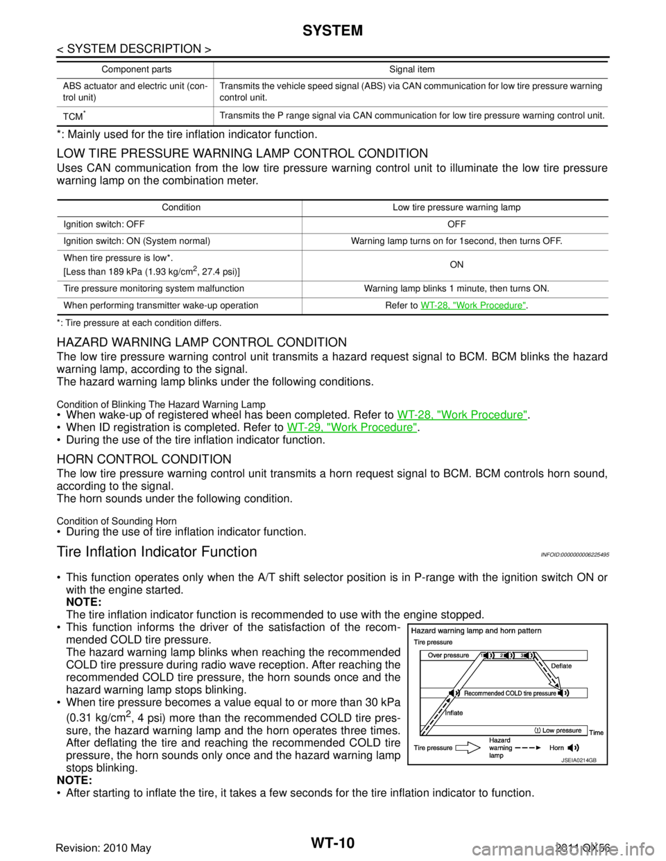
This function informs the driver of the satisfaction of the recom- mended COLD tire pressure.
The hazard warning lamp blinks when reaching the recommended
COLD tire pressure during radio wave reception. After reaching the
recommended COLD tire pressure, the horn sounds once and the
hazard warning lamp stops blinking.
When tire pressure becomes a value equal to or more than 30 kPa
(0.31 kg/cm
2, 4 psi) more than the recommended COLD tire pres-
sure, the hazard warning lamp and the horn operates three times.
After deflating the tire and reaching the recommended COLD tire
pressure, the horn sounds only once and the hazard warning lamp
stops blinking.
NOTE:
After starting to inflate the tire, it takes a few seconds for the tire inflation indicator to function.
ABS actuator and electric unit (con-
trol unit) Transmits the vehicle speed signal (ABS) via CAN communication for low tire pressure warning
control unit.
TCM
*Transmits the P range signal via CAN communication for low tire pressure warning control unit.
Component parts Signal item
Condition Low tire pr
essure warning lamp
Ignition switch: OFF OFF
Ignition switch: ON (System normal) Warning lamp turns on for 1second, then turns OFF.
When tire pressure is low*.
[Less than 189 kPa (1.93 kg/cm
2, 27.4 psi)] ON
Tire pressure monitoring system malfunction Warning lamp blinks 1 minute, then turns ON.
When performing transmitter wake-up operation Refer to WT-28, "
Work Procedure".
JSEIA0214GB
Revision: 2010 May2011 QX56
Page 5509 of 5598
TIRE INFLATION INDICATOR DOES NOT ACTIVATEWT-59
< SYMPTOM DIAGNOSIS >
C
DF
G H
I
J
K L
M A
B
WT
N
O P
TIRE INFLATION INDICATOR DOES NOT ACTIVATE
DescriptionINFOID:0000000006225540
The tire inflation indicator does not function while inflat ing a tire when the A/T shift selector position is in P-
range with the ignition switch ON or with the engine started.
NOTE:
After starting to inflate the tire, it takes a few seconds for the tire inflation indicator to function.
If there is no response for approximately 15 seconds or mo re after inflating the tires, cancel the use of the
tire inflation indicator function or move the vehicle approximately 1 m (3.2 ft) backward or forward to try
again. The air filler pressure may be weak or out of service area.
For tire inflation indicator, Refer to WT-10, "
Tire Inflation Indicator Function".
Diagnosis ProcedureINFOID:0000000006225541
1. LOCATION CHANGE
Move the vehicle to other area and repeat the procedure of the tire inflation indicator function. Refer to WT-10,
"Tire Inflation Indicator Function".
Is the function normal?
YES >> Normal (the tire inflation indicator may not operate, depending on reception condition.)
NO >> GO TO 2.
2.PERFORM LOW TIRE PRESSURE WARNI NG CONTROL UNIT SELF-DIAGNOSIS
With CONSULT-III
1. Drive for 10 minutes at a speed of 40 km/h (25 MPH) or more.
2. Stop the vehicle.
3. Perform self-diagnosis for “AIR PRESSURE MONITOR”.
Is any DTC detected?
YES >> Perform trouble diagnosis for detected DTC. Refer to WT-18, "DTC Index".
NO >> GO TO 3.
3.CHECK HAZARD WARNING LAMP OPERATION
Check hazard warning lamp operation with hazard switch.
Does the hazard warning lamp blink?
YES >> GO TO 4.
NO >> Perform trouble diagnosis for the hazard warning lamp. Refer to EXL-113, "
Symptom Table".
4.PERFORM TCM SELF-DIAGNOSIS
With CONSULT-III
Perform self-diagnosis for “TRANSMISSION”.
Is any DTC detected?
YES >> Check malfunctioning circuit. Refer to TM-78, "DTC Index".
NO >> GO TO 5.
5.CHECK HORN OPERATION
Check horn operation. Refer to SEC-143, "
ComponentFunctionCheck".
Is the operation normal?
YES >> GO TO 6.
NO >> Repair or replace error-detected parts.
6.PERFORM BCM SELF-DIAGNOSIS
With CONSULT-III
Perform self-diagnosis for “BCM”.
Is any DTC detected?
YES >> Check malfunctioning circuit. Refer to BCS-57, "DTCIndex".
NO >> Replace low tire pressure warning control unit. Refer to WT-65, "
Removal and Installation".
Revision: 2010 May2011 QX56
Page 5537 of 5598
WW-18
< SYSTEM DESCRIPTION >
DIAGNOSIS SYSTEM (IPDM E/R)
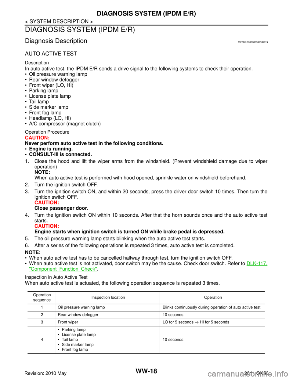
DIAGNOSIS SYSTEM (IPDM E/R)
Diagnosis DescriptionINFOID:0000000006349814
AUTO ACTIVE TEST
Description
In auto active test, the IPDM E/R sends a drive signal to the following systems to check their operation.
Oil pressure warning lamp
Rear window defogger
Front wiper (LO, HI)
Parking lamp
License plate lamp
Tail lamp
Side marker lamp
Front fog lamp
Headlamp (LO, HI)
A/C compressor (magnet clutch)
Operation Procedure
CAUTION:
Never perform auto active test in the following conditions.
Engine is running.
CONSULT-III is connected.
1. Close the hood and lift the wiper arms from the windshield. (Prevent windshield damage due to wiper
operation)
NOTE:
When auto active test is performed with hood opened, sprinkle water on windshield beforehand.
2. Turn the ignition switch OFF.
3. Turn the ignition switch ON, and within 20 seconds, pr ess the driver door switch 10 times. Then turn the
ignition switch OFF.
CAUTION:
Close passenger door.
4. Turn the ignition switch ON within 10 seconds. Af ter that the horn sounds once and the auto active test
starts.
CAUTION:
Engine starts when igniti on switch is turned ON while brake pedal is depressed.
5. The oil pressure warning lamp starts blinking when the auto active test starts.
6. After a series of the following operations is repeated 3 times, auto active test is completed.
NOTE:
When auto active test has to be cancelled halfway through test, turn the ignition switch OFF.
When auto active test is not activated, door swit ch may be the cause. Check door switch. Refer to DLK-117,
"ComponentFunctionCheck".
Inspection in Auto Active Test
When auto active test is actuated, the following operation sequence is repeated 3 times.
Operation
sequence Inspection location Operation
1 Oil pressure warning lamp Blinks continuously during operation of auto active test
2 Rear window defogger 10 seconds
3 Front wiper LO for 5 seconds → HI for 5 seconds
4 Parking lamp
License plate lamp
Tail lamp
Side marker lamp
Front fog lamp 10 seconds
Revision: 2010 May2011 QX56
Page 5540 of 5598
![INFINITI QX56 2011 Factory Service Manual
DIAGNOSIS SYSTEM (IPDM E/R)WW-21
< SYSTEM DESCRIPTION >
C
DE
F
G H
I
J
K
M A
B
WW
N
O P
ACTIVE TEST
Te s t i t e m
PUSH SW
[Off/On] Displays the status of the push-button ignition switch judged by I INFINITI QX56 2011 Factory Service Manual
DIAGNOSIS SYSTEM (IPDM E/R)WW-21
< SYSTEM DESCRIPTION >
C
DE
F
G H
I
J
K
M A
B
WW
N
O P
ACTIVE TEST
Te s t i t e m
PUSH SW
[Off/On] Displays the status of the push-button ignition switch judged by I](/manual-img/42/57033/w960_57033-5539.png)
DIAGNOSIS SYSTEM (IPDM E/R)WW-21
< SYSTEM DESCRIPTION >
C
DE
F
G H
I
J
K
M A
B
WW
N
O P
ACTIVE TEST
Te s t i t e m
PUSH SW
[Off/On] Displays the status of the push-button ignition switch judged by IPDM E/R.
INTER/NP SW
[Off/On] Displays the status of the shift position judged by IPDM E/R.
ST RLY CONT
[Off/On] Displays the status of the starter relay status signal received from BCM via CAN
communication.
IHBT RLY -REQ
[Off/On] Displays the status of the starter control relay signal received from BCM via CAN
communication.
ST/INHI RLY
[Off/ ST ON/INHI ON/UNKWN] Displays the status of the starter relay and starter control relay judged by IPDM
E/R.
DETENT SW
[Off/On] Displays the status of the A/T shift selector (detention switch) judged by IPDM E/
R.
S/L RLY -REQ
[Off/On] Displays the status of the steering lock relay signal received from BCM via CAN
communication.
S/L STATE
[LOCK/UNLK/UNKWN] Displays the status of the steering lock judged by IPDM E/R.
OIL P SW
[Open/Close] Displays the status of the oil pressure switch judged by IPDM E/R.
HOOD SW
[Off/On] Displays the status of the hood switch judged by IPDM E/R.
HL WASHER REQ
[Off/On] Displays the status of the headlamp washer request signal received from BCM via
CAN communication.
THFT HRN REQ
[Off/On] Displays the status of the theft warning horn request signal received from BCM
via CAN communication.
HORN CHIRP
[Off/On] Displays the status of the horn reminder signal received from BCM via CAN com-
munication.
Monitor Item
[Unit] MAIN SIG-
NALS Description
Test item Operation Description
CORNERING LAMP LH
NOTE:
This item is indicated, but cannot be tested.
RH
HORN On Operates horn relay for 20 ms.
REAR DEFOGGER Off OFF
On Operates the rear window defogger relay.
FRONT WIPER Off OFF
Lo Operates the front wiper relay.
Hi Operates the front wiper relay and front wiper high relay.
MOTOR FAN* 1OFF
2 Transmits 50% pulse duty signal (PWM signal) to the cooling fan control module.
3 Transmits 75% pulse duty signal (PWM signal) to the cooling fan control module.
4
Transmits 100% pulse duty signal (PWM signal) to the cooling fan control mod-
ule.
HEAD LAMP WASHER On Operates the headlamp washer relay for 1 second.
Revision: 2010 May2011 QX56