2011 INFINITI QX56 display
[x] Cancel search: displayPage 2949 of 5598

WHEEL ALIGNMENTFSU-7
< PERIODIC MAINTENANCE >
C
DF
G H
I
J
K L
M A
B
FSU
N
O P
WHEEL ALIGNMENT
InspectionINFOID:0000000006225640
DESCRIPTION
Measure wheel alignment under unladen conditions.
NOTE:
“Unladen conditions” means that fuel, engine coolant, and lubricant are full. Spare tire, jack, hand tools and
mats are in designated positions.
PRELIMINARY CHECK
Check the following:
Tires for improper air pressure and wear
Road wheels for runout: Refer to WT-64, "
Inspection".
Wheel bearing axial end play: Refer to FA X - 7 , "
Inspection" (2WD), FAX-16, "Inspection" (4WD).
Lower link and upper link ball joint axial end play: Refer to FSU-15, "
Inspection" and FSU-18, "Inspection".
Shock absorber operation.
Each mounting part of axle and suspension for looseness and deformation
Lower link for cracks, deformation and other damage
Vehicle height (posture)
GENERAL INFORMATION AND RECOMMENDATIONS
A four-wheel thrust alignment should be performed.
- This type of alignment is recomm ended for any NISSAN/INFINITI vehicle.
- The four-wheel “thrust” process helps ensure that t he vehicle is properly aligned and the steering wheel is
centered.
- The alignment rack itself should be capable of accepting any NISSAN/INFINITI vehicle.
- The rack should be checked to ensure that it is level.
Make sure the machine is properly calibrated.
- Your alignment equipment should be regularly ca librated in order to give correct information.
- Check with the manufacturer of your specific equi pment for their recommended Service/Calibration Sched-
ule.
ALIGNMENT PROCESS
IMPORTANT:
Use only the alignment specificati ons listed in this Service Manual.
When displaying the alignment settings, many alignment machines use “indicators”: (Green/red, plus or
minus, Go/No Go). Never use these indicators.
- The alignment specifications programmed into your machine that operate these indicators may not be cor-
rect.
- This may result in an ERROR.
Some newer alignment machines are equipped with an optional “Rolling Compensation” method to “com-
pensate” the sensors (alignment targets or head units). Never use this “Rolling Compensation” method.
- Use the “Jacking Compensation Method”. After installi ng the alignment targets or head units, raise the vehi-
cle and rotate the wheels 1/2 turn both ways.
- See Instructions in the alignment machine you're using for more information on this.
AdjustmentINFOID:0000000006225641
CAMBER, CASTER
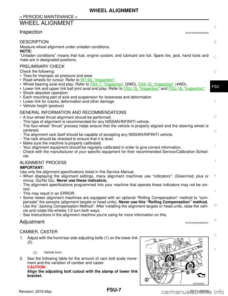
1. Adjust with the front/rear side adjusting bolts (1) on the lower link
(2).
2. See the following table for the amount of cam bolt scale move- ment and the variation of camber and caster.
CAUTION:
Align the adjusting bolt cutout with the stamp of lower link
bracket.
: Vehicle front
JPEIA0235ZZ
Revision: 2010 May2011 QX56
Page 2980 of 5598

GI-16
< HOW TO USE THIS MANUAL >
ABBREVIATIONS
I
K
L
M
N
O
ABBREVIATION DESCRIPTIONI/M Inspection and maintenanceIA Intake air
IAC Idle air control IAT Intake air temperature
IBA Intelligent brake assist IC Ignition control
ICC Intelligent cruise control
ICM Ignition control module
IPDM E/R Intelligent power distribution module engine room ISC Idle speed controlISS Input shaft speed
ABBREVIATION DESCRIPTION KS Knock sensor
ABBREVIATION DESCRIPTION LCD Liquid crystal display
LCU Local control unitLDP Lane departure prevention
LDW Lane departure warning LED Light emitting diode LH Left-hand
LIN Local interconnect network
ABBREVIATION DESCRIPTION M/T Manual transaxle/transmission
MAF Mass airflow
MAP Manifold absolute pressure MI Malfunction indicator
MIL Malfunction indicator lamp
ABBREVIATION DESCRIPTION NOX Nitrogen oxides
ABBREVIATION DESCRIPTION O2 Oxygen
O2S Oxygen sensor
OBD On board diagnostic OC Oxidation catalytic converter
OD OverdriveOL Open loop
OSS Output shaft speed
Revision: 2010 May2011 QX56
Page 3012 of 5598

GI-48
< BASIC INSPECTION >
CONSULT-III/GST CHECKING SYSTEM
CONSULT-III/GST CHECKING SYSTEM
DescriptionINFOID:0000000006280856
When CONSULT-III/GST is connected with a data link connector
(A) equipped on the vehicle side, it will communicate with the con-
trol unit equipped in the vehicle and then enable various kinds of
diagnostic tests.
Refer to “CONSULT-III Software Operation Manual” for more infor- mation.
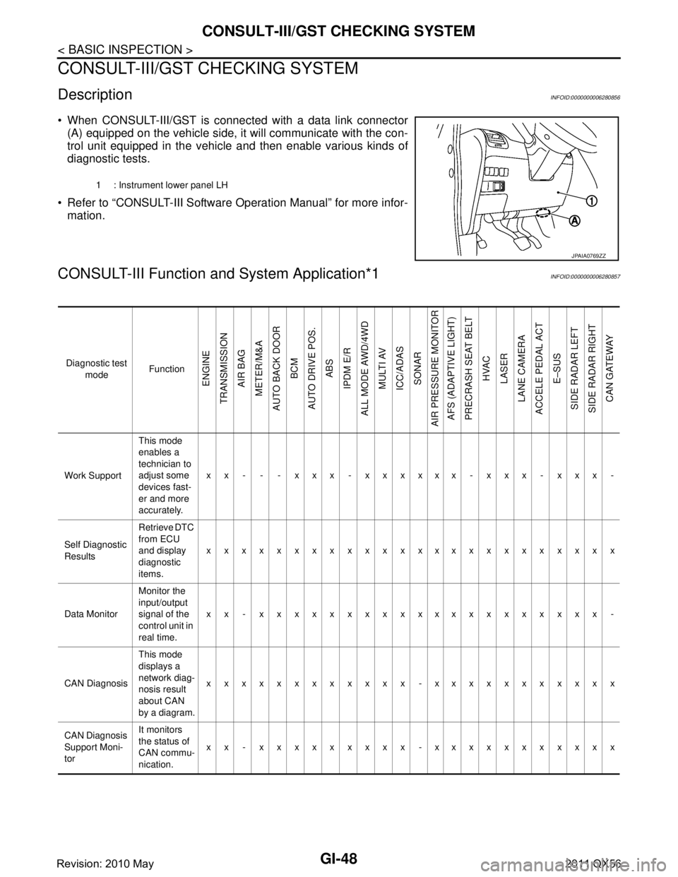
CONSULT-III Function a nd System Application*1INFOID:0000000006280857
1 : Instrument lower panel LH
JPAIA0769ZZ
Diagnostic test
mode Function
ENGINE
TRANSMISSION AIR BAG
METER/M&A
AUTO BACK DOOR BCM
AUTO DRIVE POS. ABS
IPDM E/R
ALL MODE AWD/4WD MULTI AV
ICC/ADAS SONAR
AIR PRESSURE MONITOR AFS (ADAPTIVE LIGHT)
PRECRASH SEAT BELT HVAC
LASER
LANE CAMERA
ACCELE PEDAL ACT
E–SUS
SIDE RADAR LEFT
SIDE RADAR RIGHT CAN GATEWAY
Work Support This mode
enables a
technician to
adjust some
devices fast-
er and more
accurately.xx - - - xxx - xxxxxx - xxx - xxx -
Self Diagnostic
Results Retrieve DTC
from ECU
and display
diagnostic
items.
xxxxxxxxxxxxxxxxxxxxxxxx
Data Monitor Monitor the
input/output
signal of the
control unit in
real time.xx - xxxxxxxxxxxxxxxxxxxx -
CAN Diagnosis This mode
displays a
network diag-
nosis result
about CAN
by a diagram.xxxxxxxxxxxx -xxxxxxxxxxx
CAN Diagnosis
Support Moni-
tor It monitors
the status of
CAN commu-
nication.
xx - xxxxxxxxx -xxxxxxxxxxx
Revision: 2010 May2011 QX56
Page 3013 of 5598

CONSULT-III/GST CHECKING SYSTEMGI-49
< BASIC INSPECTION >
C
DE
F
G H
I
J
K L
M B
GI
N
O P
x: Applicable
*1: If GST application is equipped , functions in accordance with SAE J1 979 and ISO 15031-5 can be used.
Active Test
Send the
drive signal
from CON-
SULT-III to
the actuator.
The opera-
tion check
can be per-
formed.x - - - - xxxx - - xxxx - x - - xxxx -
DTC & SRT
confirmation The status of
system moni-
toring tests
and the self-
diagnosis
status/result
can be con-
firmed.
xx----------------------
ECU Identifica-
tion Display the
ECU identifi-
cation num-
ber (part
number etc.)
of the select-
ed system.
xxx - xxxxxxxxxxxxxxxxxxxx
Function Test This mode
can show re-
sults of self-
diagnosis of
ECU with ei-
ther “OK” or
“NG”. For en-
gine, more
practical
tests regard-
ing sensors/
switches and/
or actuators
are available.xxx----x----------------
Configuration Function to
READ/
WRITE vehi-
cle configura-
tion.-----x----x------------x
Special
Function Other results
or histories,
etc. that are
recorded in
ECU are dis-
played.
-xxx--------------------
Diagnostic test
mode Function
ENGINE
TRANSMISSION AIR BAG
METER/M&A
AUTO BACK DOOR
BCM
AUTO DRIVE POS. ABS
IPDM E/R
ALL MODE AWD/4WD
MULTI AV
ICC/ADAS SONAR
AIR PRESSURE MONITOR AFS (ADAPTIVE LIGHT)
PRECRASH SEAT BELT HVAC
LASER
LANE CAMERA
ACCELE PEDAL ACT E–SUS
SIDE RADAR LEFT
SIDE RADAR RIGHT CAN GATEWAY
Revision: 2010 May2011 QX56
Page 3063 of 5598

PRECAUTIONSHA-7
< PRECAUTION >
C
DE
F
G H
J
K L
M A
B
HA
N
O P
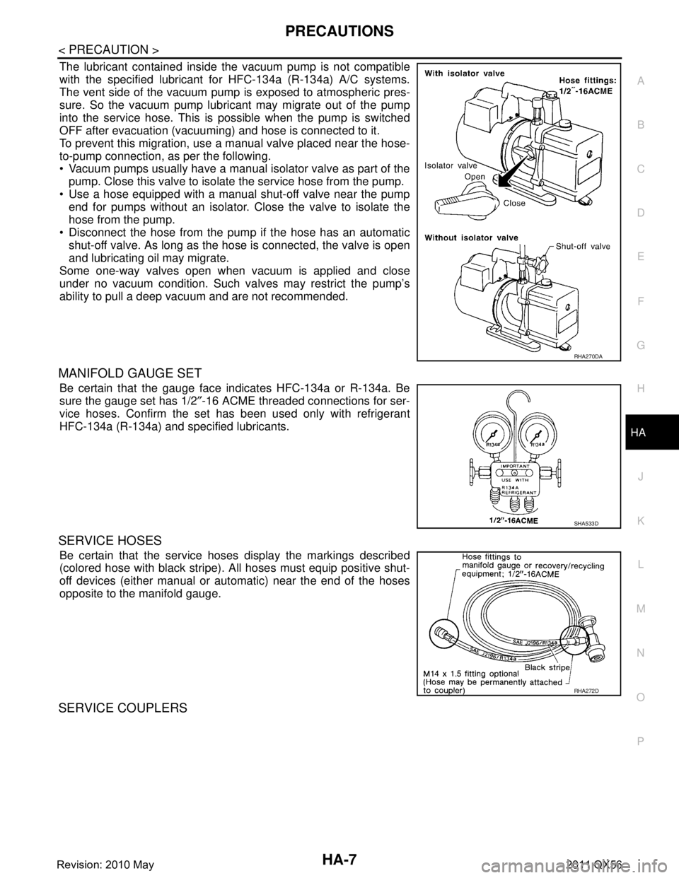
The lubricant contained inside the vacuum pump is not compatible
with the specified lubricant for HFC-134a (R-134a) A/C systems.
The vent side of the vacuum pump is exposed to atmospheric pres-
sure. So the vacuum pump lubricant may migrate out of the pump
into the service hose. This is possible when the pump is switched
OFF after evacuation (vacuuming) and hose is connected to it.
To prevent this migration, use a manual valve placed near the hose-
to-pump connection, as per the following.
Vacuum pumps usually have a manual isolator valve as part of the
pump. Close this valve to isolate the service hose from the pump.
Use a hose equipped with a manual shut-off valve near the pump end for pumps without an isolator. Close the valve to isolate the
hose from the pump.
Disconnect the hose from the pum p if the hose has an automatic
shut-off valve. As long as the hose is connected, the valve is open
and lubricating oil may migrate.
Some one-way valves open when vacuum is applied and close
under no vacuum condition. Such valves may restrict the pump’s
ability to pull a deep vacuum and are not recommended.
MANIFOLD GAUGE SET
Be certain that the gauge face indicates HFC-134a or R-134a. Be
sure the gauge set has 1/2 ″-16 ACME threaded connections for ser-
vice hoses. Confirm the set has been used only with refrigerant
HFC-134a (R-134a) and specified lubricants.
SERVICE HOSES
Be certain that the service hoses display the markings described
(colored hose with black stripe). A ll hoses must equip positive shut-
off devices (either manual or automatic) near the end of the hoses
opposite to the manifold gauge.
SERVICE COUPLERS
RHA270DA
SHA533D
RHA272D
Revision: 2010 May2011 QX56
Page 3064 of 5598

HA-8
< PRECAUTION >
PRECAUTIONS
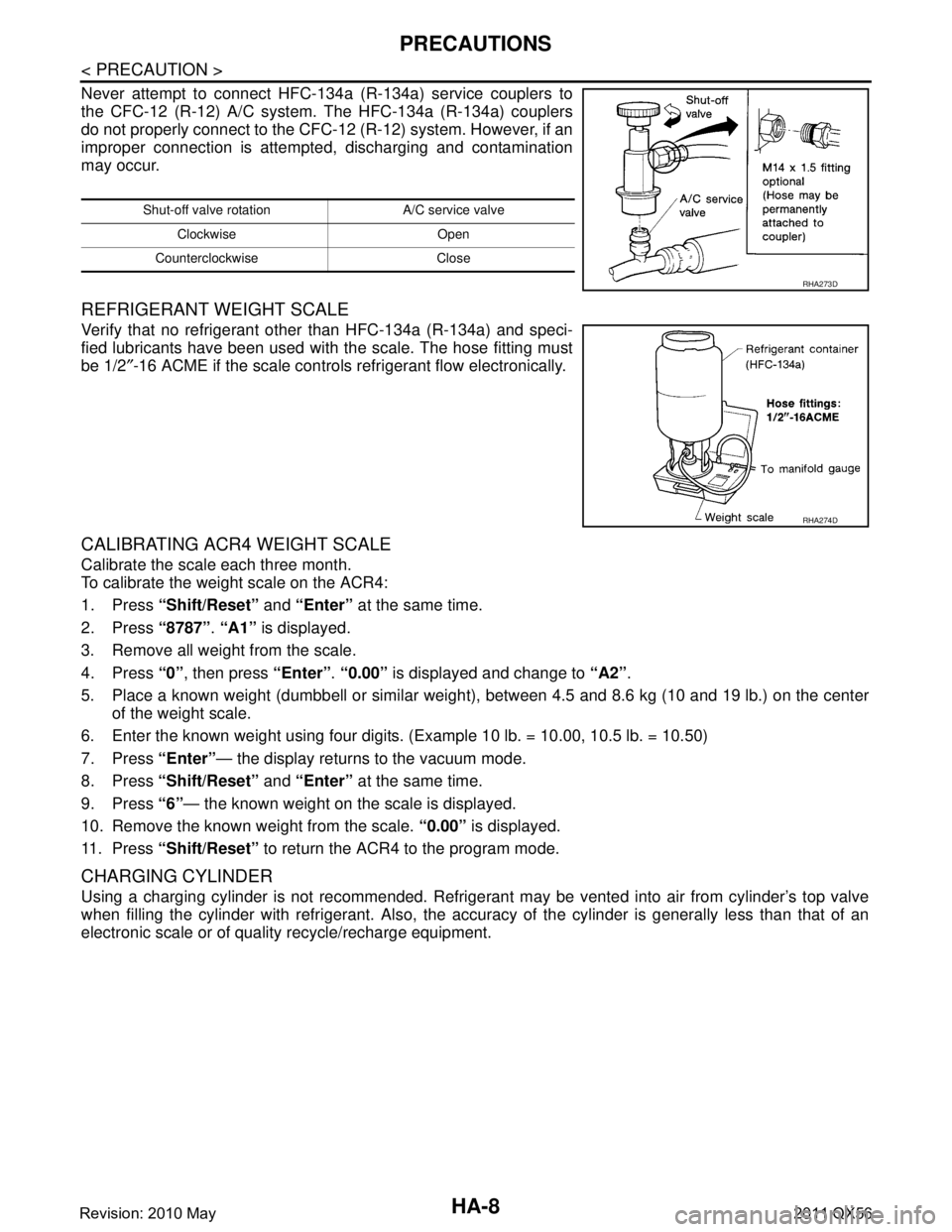
Never attempt to connect HFC-134a (R-134a) service couplers to
the CFC-12 (R-12) A/C system. The HFC-134a (R-134a) couplers
do not properly connect to the CFC-12 (R-12) system. However, if an
improper connection is attempted, discharging and contamination
may occur.
REFRIGERANT WEIGHT SCALE
Verify that no refrigerant other than HFC-134a (R-134a) and speci-
fied lubricants have been used with the scale. The hose fitting must
be 1/2″-16 ACME if the scale controls refrigerant flow electronically.
CALIBRATING ACR4 WEIGHT SCALE
Calibrate the scale each three month.
To calibrate the weight scale on the ACR4:
1. Press “Shift/Reset” and “Enter” at the same time.
2. Press “8787”. “A1” is displayed.
3. Remove all weight from the scale.
4. Press “0”, then press “Enter”. “0.00” is displayed and change to “A2”.
5. Place a known weight (dumbbell or similar weight ), between 4.5 and 8.6 kg (10 and 19 lb.) on the center
of the weight scale.
6. Enter the known weight using four digi ts. (Example 10 lb. = 10.00, 10.5 lb. = 10.50)
7. Press “Enter”— the display returns to the vacuum mode.
8. Press “Shift/Reset” and “Enter” at the same time.
9. Press “6”— the known weight on the scale is displayed.
10. Remove the known weight from the scale. “0.00” is displayed.
11. Press “Shift/Reset” to return the ACR4 to the program mode.
CHARGING CYLINDER
Using a charging cylinder is not recommended. Refrigerant may be vented into air from cylinder’s top valve
when filling the cylinder with refrigerant. Also, the accu racy of the cylinder is generally less than that of an
electronic scale or of quality recycle/recharge equipment.
Shut-off valve rotati on A/C service valve
Clockwise Open
Counterclockwise Close
RHA273D
RHA274D
Revision: 2010 May2011 QX56
Page 3112 of 5598
![INFINITI QX56 2011 Factory Service Manual
HAC-6
< SYSTEM DESCRIPTION >[AUTOMATIC AIR CONDITIONING]
COMPONENT PARTS
SYSTEM DESCRIPTION
COMPONENT PARTS
FRONT AUTOMATIC AIR CONDITIONING SYSTEM
FRONT AUTOMATIC AIR CONDITIONING
SYSTEM : Componen INFINITI QX56 2011 Factory Service Manual
HAC-6
< SYSTEM DESCRIPTION >[AUTOMATIC AIR CONDITIONING]
COMPONENT PARTS
SYSTEM DESCRIPTION
COMPONENT PARTS
FRONT AUTOMATIC AIR CONDITIONING SYSTEM
FRONT AUTOMATIC AIR CONDITIONING
SYSTEM : Componen](/manual-img/42/57033/w960_57033-3111.png)
HAC-6
< SYSTEM DESCRIPTION >[AUTOMATIC AIR CONDITIONING]
COMPONENT PARTS
SYSTEM DESCRIPTION
COMPONENT PARTS
FRONT AUTOMATIC AIR CONDITIONING SYSTEM
FRONT AUTOMATIC AIR CONDITIONING
SYSTEM : Component Parts Location
INFOID:0000000006275848
1. Preset switch 2. Engine coolant temperature sensor
Refer to EC-16, "
Component Parts
Location". 3. IPDM E/R
Refer to PCS-4, "
Component Parts
Location".
4. ECM Refer to EC-16, "
Component Parts
Location"
5. Refrigerant pressure sensor 6. Ambient sensor
7. Magnet clutch 8. AV control unit Refer to AV- 9 , "
Component Parts Lo-
cation". 9. Combination meter
Refer to MWI-6, "
METER SYSTEM :
Component Parts Location".
10. Sunload sensor 11. Front display 12. Upper ventilator door motor
JMIIA0812ZZ
Revision: 2010 May2011 QX56
Page 3113 of 5598
![INFINITI QX56 2011 Factory Service Manual
COMPONENT PARTSHAC-7
< SYSTEM DESCRIPTION > [AUTOMATIC AIR CONDITIONING]
C
D
E
F
G H
J
K L
M A
B
HAC
N
O P
FRONT AUTOMATIC AIR CONDITIONING SYSTEM : Component Description
INFOID:0000000006275849
13. INFINITI QX56 2011 Factory Service Manual
COMPONENT PARTSHAC-7
< SYSTEM DESCRIPTION > [AUTOMATIC AIR CONDITIONING]
C
D
E
F
G H
J
K L
M A
B
HAC
N
O P
FRONT AUTOMATIC AIR CONDITIONING SYSTEM : Component Description
INFOID:0000000006275849
13.](/manual-img/42/57033/w960_57033-3112.png)
COMPONENT PARTSHAC-7
< SYSTEM DESCRIPTION > [AUTOMATIC AIR CONDITIONING]
C
D
E
F
G H
J
K L
M A
B
HAC
N
O P
FRONT AUTOMATIC AIR CONDITIONING SYSTEM : Component Description
INFOID:0000000006275849
13. Aspirator 14. Front air mix door motor (Driver side) 15. Intake sensor
16. Front mode door motor 17. Front air mix door motor (Passenger
side)18. Intake door motor
19. Front blower motor 20. A/C auto amp. 21. Front in-vehicle sensor
A. Left side of heater & cooling unit as- sembly B. Right side of heater & cooling unit as-
sembly C. Back side of blower unit assembly
D. Cluster lid C is removed E. Ins trument lower panel LH is re-
moved
Component Description
Ambient sensor Ambient sensor measures ambient air temperature. The sensor uses a
thermistor which is sensitive to the change in temperature. The electrical
resistance of the thermistor decreases as temperature increases.
AV c o n t r o l u n i t AV control unit transmits front A/C control operation signal to A/C auto amp.
via CAN communication line.
A/C auto amp. A/C auto amp. controls front automatic air conditioning system by inputting
and calculating signals from each sensor and each switch. A/C auto amp.
has self-diagnosis function. Diagnosis of front automatic air conditioning
system can be performed quickly.
Blower unit Front blower motor Refer to
HAC-12
.
Intake door motor The LCU (Local Control Unit) is installed to intake door motor so as to per-
form the multiplex commu
nication control (LIN).
Refer to HAC-18, "
FRONT AUTOMATIC AIR CONDITIONING SYSTEM :
Door Control".
Combination meter Combination meter transmits vehicle speed signal to A/C auto amp. via
CAN communication line.
ECM ECM controls compressor according to status of engine and refrigerant.
ECM transmits engine coolant temperature signal to A/C auto amp. via
CAN communication line.
Engine coolant temperature sensor Engine coolant temperature sensor measures engine coolant temperature.
The sensor uses a thermistor which is sensitive to the change in tempera-
ture. The electrical resistance of the thermistor decreases as temperature
increases.
Front display Front display indicates operation status of front automatic air conditioning
system.
Front in-vehicle sensor Front in-vehicle sensor measures temperature of intake air that flows
through aspirator to passenger room. The sensor uses a thermistor which
is sensitive to the change in temperature. The electrical resistance of the
thermistor decreases as temperature increases.
Revision: 2010 May2011 QX56