2011 INFINITI QX56 key
[x] Cancel search: keyPage 644 of 5598
![INFINITI QX56 2011 Factory Service Manual
EXCESSIVE OPERATION FREQUENCYBRC-127
< SYMPTOM DIAGNOSIS > [WITH VDC]
C
D
E
G H
I
J
K L
M A
B
BRC
N
O P
SYMPTOM DIAGNOSIS
EXCESSIVE OPERATION FREQUENCY
DescriptionINFOID:0000000006222657
VDC function INFINITI QX56 2011 Factory Service Manual
EXCESSIVE OPERATION FREQUENCYBRC-127
< SYMPTOM DIAGNOSIS > [WITH VDC]
C
D
E
G H
I
J
K L
M A
B
BRC
N
O P
SYMPTOM DIAGNOSIS
EXCESSIVE OPERATION FREQUENCY
DescriptionINFOID:0000000006222657
VDC function](/manual-img/42/57033/w960_57033-643.png)
EXCESSIVE OPERATION FREQUENCYBRC-127
< SYMPTOM DIAGNOSIS > [WITH VDC]
C
D
E
G H
I
J
K L
M A
B
BRC
N
O P
SYMPTOM DIAGNOSIS
EXCESSIVE OPERATION FREQUENCY
DescriptionINFOID:0000000006222657
VDC function, TCS function, ABS functi on, EBD function, hill start assist function and brake limited slip differ-
ential (BLSD) function operates in excessive operation frequency.
Diagnosis ProcedureINFOID:0000000006222658
1.CHECK BRAKING FORCE
Check brake force using a brake tester.
Is the inspection result normal?
YES >> GO TO 2.
NO >> Check brake system.
2.CHECK FRONT AND REAR AXLE
Check that there is no excessive looseness in front and rear axle.
Front axle: Refer to FA X - 7 , "
Inspection" (2WD), FAX-16, "Inspection" (4WD).
Rear axle: Refer to RAX-5, "
Inspection"
Is the inspection result normal?
YES >> GO TO 3.
NO >> Repair or replace error-detected parts.
3.CHECK WHEEL SENSOR
Check wheel sensor.
Check installation and damage of wheel sensor.
Check connection of wheel sensor harness connector.
Check terminal of wheel sensor harness connector.
Is the inspection result normal?
YES >> GO TO 4.
NO >> Repair or replace wheel sensor. Front wheel sensor: Refer to BRC-134, "
FRONT WHEEL SENSOR : Removal and Installation".
Rear wheel sensor: Refer to BRC-135, "
REAR WHEEL SENSOR : Removal and Installation".
4.CHECK WARNING LAMP TURNS OFF
Check that ABS warning lamp, brake warning lamp and VDC warning lamp turn OFF approx. 1 second after
key switch is turned ON and stay in OFF status during driving.
CAUTION:
Brake warning lamp turns ON when parking brake is operated (parking brake switch is ON) or brake
fluid is less than the specified level (brake fluid level switch is ON).
Is the inspection result normal?
YES >> Normal
NO >> Perform self-diagnosis for “ABS” with CONSULT-III.
Revision: 2010 May2011 QX56
Page 647 of 5598
![INFINITI QX56 2011 Factory Service Manual
BRC-130
< SYMPTOM DIAGNOSIS >[WITH VDC]
DOES NOT OPERATE
DOES NOT OPERATE
DescriptionINFOID:0000000006222663
VDC function, TCS function, ABS functi
on, EBD function, hill start assist function and br INFINITI QX56 2011 Factory Service Manual
BRC-130
< SYMPTOM DIAGNOSIS >[WITH VDC]
DOES NOT OPERATE
DOES NOT OPERATE
DescriptionINFOID:0000000006222663
VDC function, TCS function, ABS functi
on, EBD function, hill start assist function and br](/manual-img/42/57033/w960_57033-646.png)
BRC-130
< SYMPTOM DIAGNOSIS >[WITH VDC]
DOES NOT OPERATE
DOES NOT OPERATE
DescriptionINFOID:0000000006222663
VDC function, TCS function, ABS functi
on, EBD function, hill start assist function and brake limited slip differ-
ential (BLSD) function does not operate.
Diagnosis ProcedureINFOID:0000000006222664
CAUTION:
VDC function, ABS function and EBD function never operate when the vehicle speed is 10 km/h (6.2
MPH) or less.
TCS function, hill start assist fu nction and brake limited slip diffe rential (BLSD) function operates
when the vehicle speed is 0 km/h (0 MPH) (the vehicle is in stop status).
VDC function and TCS function never operate wh en VDC OFF switch is operated (when VDC OFF
indicator lamp turns ON).
1.CHECK ABS WARNING LAMP
Check that ABS warning lamp, brake warning lamp and VDC warning lamp turn ON and turn OFF approx. 1
second after key switch is turned ON. Check that ABS warning lamp, brake warning lamp and VDC warning
lamp and stay in OFF status during driving.
CAUTION:
Brake warning lamp turns ON when parking brake is operated (parking brake switch is ON) or brake
fluid is less than the specified level (brake fluid level switch is ON).
Is the inspection result normal?
YES >> Normal
NO >> Perform self-diagnosis for “ABS” with CONSULT-III.
Revision: 2010 May2011 QX56
Page 1299 of 5598
![INFINITI QX56 2011 Factory Service Manual
DAS-334
< BASIC INSPECTION >[LDW & LDP]
DIAGNOSIS AND REPAIR WORK FLOW
Utilize a work sheet sample to organize all of the information for troubleshooting.
KEY POINTS WHAT..... System and functions
INFINITI QX56 2011 Factory Service Manual
DAS-334
< BASIC INSPECTION >[LDW & LDP]
DIAGNOSIS AND REPAIR WORK FLOW
Utilize a work sheet sample to organize all of the information for troubleshooting.
KEY POINTS WHAT..... System and functions
](/manual-img/42/57033/w960_57033-1298.png)
DAS-334
< BASIC INSPECTION >[LDW & LDP]
DIAGNOSIS AND REPAIR WORK FLOW
Utilize a work sheet sample to organize all of the information for troubleshooting.
KEY POINTS WHAT..... System and functions
WHEN..... Date, Frequencies
WHERE..... Road conditions
HOW..... Operating conditions, Symptoms
WORK SHEET SAMPLE
JSOIA0287GB
Revision: 2010 May2011 QX56
Page 1499 of 5598

DIAGNOSIS SYSTEM (BCM)DEF-7
< SYSTEM DESCRIPTION >
C
DE
F
G H
I
J
K
M A
B
DEF
N
O P
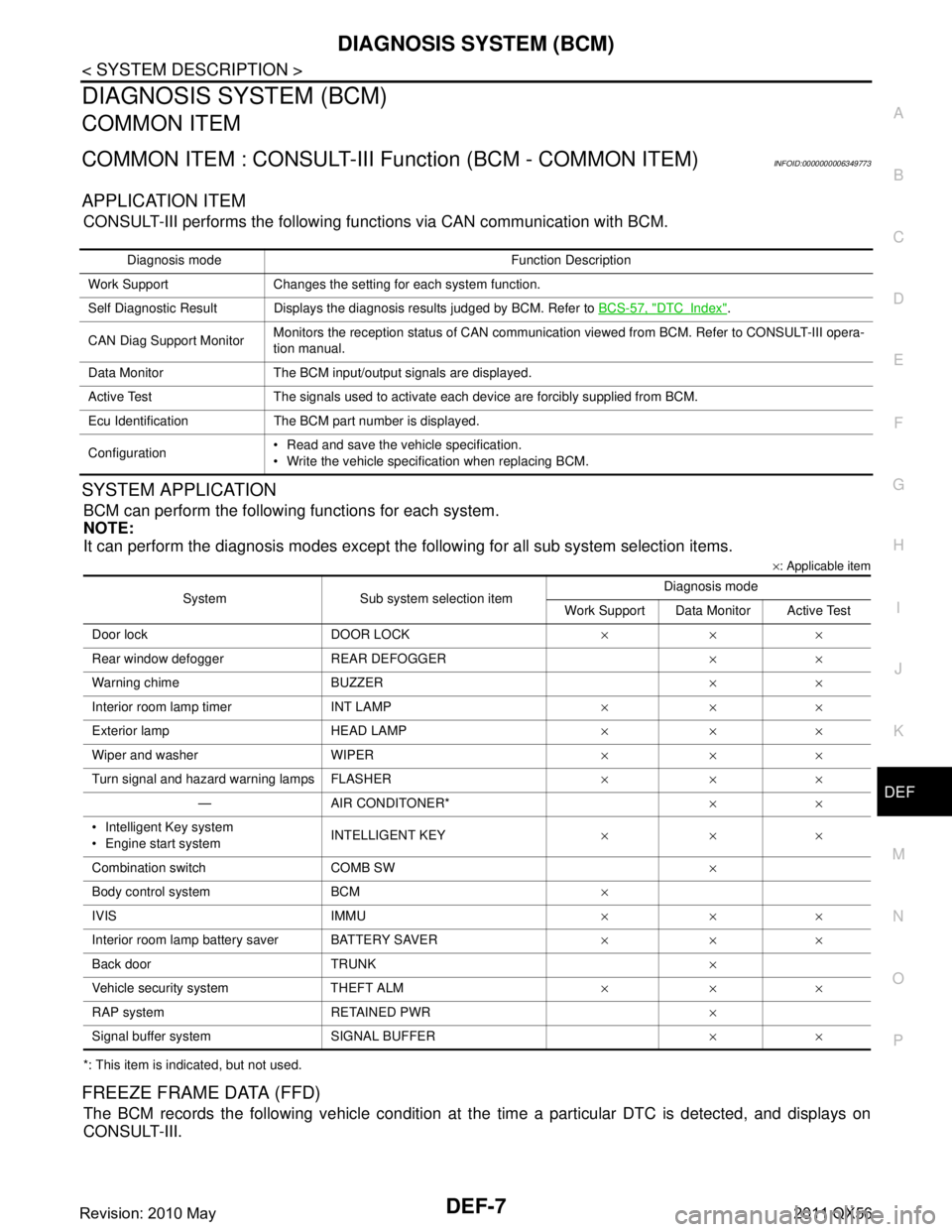
DIAGNOSIS SYSTEM (BCM)
COMMON ITEM
COMMON ITEM : CONSULT-III Fu nction (BCM - COMMON ITEM)INFOID:0000000006349773
APPLICATION ITEM
CONSULT-III performs the following functions via CAN communication with BCM.
SYSTEM APPLICATION
BCM can perform the following functions for each system.
NOTE:
It can perform the diagnosis modes except the following for all sub system selection items.
×: Applicable item
*: This item is indicated, but not used.
FREEZE FRAME DATA (FFD)
The BCM records the following vehicle condition at the time a particular DTC is detected, and displays on
CONSULT-III.
Diagnosis mode Function Description
Work Support Changes the setting for each system function.
Self Diagnostic Result Displays the diagnosis results judged by BCM. Refer to BCS-57, "
DTCIndex".
CAN Diag Support Monitor Monitors the reception status of CAN communication viewed from BCM. Refer to CONSULT-III opera-
tion manual.
Data Monitor The BCM input/output signals are displayed.
Active Test The signals used to activate each device are forcibly supplied from BCM.
Ecu Identification The BCM part number is displayed.
Configuration Read and save the vehicle specification.
Write the vehicle specification when replacing BCM.
System Sub system selection item Diagnosis mode
Work Support Data Monitor Active Test
Door lock DOOR LOCK ×××
Rear window defo gger REAR DEFOGGER ××
Warning chime BUZZER ××
Interior room lamp timer INT LAMP ×××
Exterior lamp HEAD LAMP ×××
Wiper and washer WIPER ×××
Turn signal and hazard warning lamps FLASHER ×××
— AIR CONDITONER* ××
Intelligent Key system
Engine start system INTELLIGENT KEY
×××
Combination switch COMB SW ×
Body control system BCM ×
IVIS IMMU ×××
Interior room lamp battery saver BATTERY SAVER ×××
Back door TRUNK ×
Vehicle security system THEFT ALM ×××
RAP system RETAINED PWR ×
Signal buffer system SIGNAL BUFFER ××
Revision: 2010 May2011 QX56
Page 1537 of 5598

DLK-1
BODY EXTERIOR, DOORS, ROOF & VEHICLE SECURITY
C
D
E
F
G H
I
J
L
M
SECTION DLK
A
B
DLK
N
O P
CONTENTS
DOOR & LOCK
PRECAUTION ................ ...............................8
PRECAUTIONS .............................................. .....8
Precaution for Supplemental Restraint System
(SRS) "AIR BAG" and "SEAT BELT PRE-TEN-
SIONER" ............................................................. ......
8
Precaution Necessary for Steering Wheel Rota-
tion after Battery Disconnect .....................................
8
Precautions For Xenon Headlamp Service ...............9
Work ..........................................................................9
PREPARATION ...........................................10
PREPARATION .............................................. ....10
Commercial Service Tools .................................. ....10
SYSTEM DESCRIPTION .............................11
COMPONENT PARTS ................................... ....11
DOOR LOCK SYSTEM .............................................11
DOOR LOCK SYSTEM :
Component Parts Location ................................ ....
11
DOOR LOCK SYSTEM : Component Description ....12
AUTOMATIC BACK DOOR SYSTEM .......................13
AUTOMATIC BACK DOOR SYSTEM :
Component Parts Location ................................ ....
14
AUTOMATIC BACK DOOR SYSTEM :
Component Description ..........................................
15
SYSTEM (POWER DOOR LOCK SYSTEM) .....16
System Diagram .................................................. ....16
System Description .................................................16
SYSTEM (INTELLIGENT KEY SYSTEM) ..........18
INTELLIGENT KEY SYSTEM ...................................18
INTELLIGENT KEY SYSTEM : System Diagram ....18
INTELLIGENT KEY SYSTEM : System Descrip-
tion ..........................................................................
18
DOOR LOCK FUNCTION ...................................... ....19
DOOR LOCK FUNCTION : System Diagram ..........19
DOOR LOCK FUNCTION : System Description .....19
BACK DOOR OPEN FUNCTION ........................... ....21
BACK DOOR OPEN FUNCTION : System Dia-
gram ........................................................................
21
BACK DOOR OPEN FUNCTION : System De-
scription ...................................................................
21
REMOTE KEYLESS ENTRY FUNCTION ..................23
REMOTE KEYLESS ENTRY FUNCTION : Sys-
tem Diagram ........................................................ ....
23
REMOTE KEYLESS ENTRY FUNCTION : Sys-
tem Description ........................................................
23
KEY REMINDER FUNCTION ................................ ....25
KEY REMINDER FUNCTION : System Diagram ....25
KEY REMINDER FUNCTION : System Descrip-
tion ...........................................................................
26
WELCOME LIGHT FUNCTION ............................. ....26
WELCOME LIGHT FUNCTION : System Diagram
....
26
WELCOME LIGHT FUNCTION : System Descrip-
tion ...........................................................................
26
WARNING FUNCTION .......................................... ....27
WARNING FUNCTION : System Description ..........27
SYSTEM (AUTOMATIC BACK DOOR SYS-
TEM) ..................................................................
31
System Diagram .................................................. ....31
System Description ..................................................31
SYSTEM (INTEGRATED HOMELINK
TRANSMITTER) ................................................
37
System Description .............................................. ....37
DIAGNOSIS SYSTEM (BCM) ...........................38
COMMON ITEM ..................................................... ....38
COMMON ITEM : CONSULT-III Function (BCM -
COMMON ITEM) .....................................................
38
Revision: 2010 May2011 QX56
Page 1538 of 5598

DLK-2
DOOR LOCK .............................................................39
DOOR LOCK : CONSULT-III Function (BCM -
DOOR LOCK) .........................................................
39
INTELLIGENT KEY ................................................ ...40
INTELLIGENT KEY : CONSULT-III Function
(BCM - INTELLIGENT KEY) ...................................
41
TRUNK ................................................................... ...44
TRUNK : CONSULT-III Function (BCM - TRUNK) ...44
DIAGNOSIS SYSTEM (AUTOMATIC BACK
DOOR CONTROL UNIT) ...................................
45
CONSULT-III Function (AUTOMATIC BACK
DOOR CONTROL UNIT) ..................................... ...
45
ECU DIAGNOSIS INFORMATION ..............46
BCM ................................................................ ...46
List of ECU Reference ......................................... ...46
AUTOMATIC BACK DOOR CONTROL MOD-
ULE ....................................................................
47
Reference Value .................................................. ...47
Fail Safe .................................................................49
DTC Inspection Priority Chart ..............................49
DTC Index ..............................................................50
WIRING DIAGRAM .....................................51
DOOR & LOCK SYSTEM ............................... ...51
Wiring Diagram - DOOR & LOCK SYSTEM - ...... ...51
AUTOMATIC BACK DOOR SYSTEM ...............66
Wiring Diagram - AUTOMATIC BACK DOOR
SYSTEM - ............................................ ...................
66
INTEGRATED HOMELINK TRANSMITTER
SYSTEM ............ .............................................. ...
75
Wiring Diagram - INTEGRATED HOMELINK
TRANSMITTER SYSTEM - ....................................
75
BASIC INSPECTION ...... .............................77
DIAGNOSIS AND REPAIR WORK FLOW ..... ...77
Work Flow ............................................................ ...77
INSPECTION AND ADJUSTMENT ...................80
ADDITIONAL SERVICE WHEN REMOVING BAT-
TERY NEGATIVE TERMINAL ............................... ...
80
ADDITIONAL SERVICE WHEN REMOVING
BATTERY NEGATIVE TERMINAL : Description ....
80
ADDITIONAL SERVICE WHEN REMOVING
BATTERY NEGATIVE TERMINAL : Work Proce-
dure ........................................................................
80
ADDITIONAL SERVICE WHEN REPLACING
CONTROL UNIT (BCM) ......................................... ...
80
ADDITIONAL SERVICE WHEN REPLACING
CONTROL UNIT (BCM) : Description ....................
80
ADDITIONAL SERVICE WHEN REPLACING
CONTROL UNIT (BCM) : Work Procedure .......... ...
80
ADDITIONAL SERVICE WHEN REPLACING (AU-
TOMATIC BACK DOOR CONTROL MODULE) .......
80
ADDITIONAL SERVICE WHEN REPLACING
(AUTOMATIC BACK DOOR CONTROL MOD-
ULE) : Description ................................................ ...
80
ADDITIONAL SERVICE WHEN REPLACING
(AUTOMATIC BACK DOOR CONTROL MOD-
ULE) : Work Procedure ........................................ ...
80
DTC/CIRCUIT DIAGNOSIS ........................82
U1000 CAN COMM CIRCUIT ......................... ...82
Description ........................................................... ...82
DTC Logic ...............................................................82
Diagnosis Procedure ...............................................82
U1010 CONTROL UNIT (CAN) .........................83
DTC Logic ............................................................ ...83
Diagnosis Procedure ...............................................83
B2401 IGNITION POWER SUPPLY CIRCUIT ...84
DTC Logic ............................................................ ...84
Diagnosis Procedure ...............................................84
B2403 ENCODER ..............................................85
DTC Logic ............................................................ ...85
Diagnosis Procedure ...............................................85
B2409 HALF LATCH SWITCH ..........................86
DTC Logic ............................................................ ...86
Diagnosis Procedure ...............................................86
Component Inspection ............................................87
B2416 TOUCH SENSOR RH ............................88
DTC Logic ............................................................ ...88
Diagnosis Procedure ...............................................88
Component Inspection ............................................89
B2417 TOUCH SENSOR LH .............................90
DTC Logic ............................................................ ...90
Diagnosis Procedure ...............................................90
Component Inspection ............................................91
B2419 OPEN SWITCH ......................................92
DTC Logic ............................................................ ...92
Diagnosis Procedure ...............................................92
Component Inspection ............................................93
B2420 CLOSE SWITCH ....................................95
DTC Logic ............................................................ ...95
Diagnosis Procedure ...............................................95
Component Inspection ............................................96
B2421 CLUTCH OPERATION TIME .................97
DTC Logic ............................................................ ...97
Diagnosis Procedure ...............................................97
B2422 BACK DOOR STATE .............................98
DTC Logic ............................................................ ...98
Revision: 2010 May2011 QX56
Page 1539 of 5598

DLK-3
C
DE
F
G H
I
J
L
M A
B
DLK
N
O P
Diagnosis Procedure ...........................................
....
98
B2423 AUTOMATIC BACK DOOR MOTOR
OPERATION TIME .............................................
99
DTC Logic ........................................................... ....99
Diagnosis Procedure ...............................................99
B2424 CLOSURE CONDITION ........................100
DTC Logic ........................................................... ..100
Diagnosis Procedure .............................................100
Component Inspection ..........................................101
B2425 AUTOMATIC BACK DOOR CONTROL
UNIT ..................................................................
103
DTC Logic ........................................................... ..103
Diagnosis Procedure .............................................103
B2621 INSIDE ANTENNA ................................104
DTC Logic ........................................................... ..104
Diagnosis Procedure .............................................104
B2622 INSIDE ANTENNA ................................106
DTC Logic ........................................................... ..106
Diagnosis Procedure .............................................106
B2623 INSIDE ANTENNA ................................108
DTC Logic ........................................................... ..108
Diagnosis Procedure .............................................108
B2626 OUTSIDE ANTENNA ............................110
DTC Logic ........................................................... ..110
Diagnosis Procedure .............................................110
B2627 OUTSIDE ANTENNA ............................112
DTC Logic ........................................................... ..112
Diagnosis Procedure .............................................112
B2628 OUTSIDE ANTENNA ............................114
DTC Logic ........................................................... ..114
Diagnosis Procedure .............................................114
POWER SUPPLY AND GROUND CIRCUIT ....116
AUTOMATIC BACK DOOR CONTROL UNIT ...... ..116
AUTOMATIC BACK DOOR CONTROL UNIT : Di-
agnosis Procedure ................................................
116
DOOR SWITCH ................................................117
Component Function Check .............................. ..117
Diagnosis Procedure .............................................117
Component Inspection ..........................................119
BACK DOOR SWITCH .....................................120
Component Function Check .............................. ..120
Diagnosis Procedure .............................................120
Component Inspection ..........................................121
DOOR LOCK AND UNLOCK SWITCH ............122
DRIVER SIDE ........................................................ ..122
DRIVER SIDE : Component Function Check ......122
DRIVER SIDE : Diagnosis Procedure ...................122
PASSENGER SIDE ..................................................122
PASSENGER SIDE :
Component Function Check .............................. ..
122
PASSENGER SIDE : Diagnosis Procedure ..........122
DOOR LOCK ACTUATOR ..............................123
DRIVER SIDE ......................................................... ..123
DRIVER SIDE : Component Function Check ......123
DRIVER SIDE : Diagnosis Procedure ...................123
PASSENGER SIDE ..................................................124
PASSENGER SIDE :
Component Function Check .............................. ..
124
PASSENGER SIDE : Diagnosis Procedure ..........124
REAR LH ................................................................ ..125
REAR LH : Component Function Check ..............125
REAR LH : Diagnosis Procedure ...........................125
REAR RH ............................................................... ..126
REAR RH : Component Function Check .............126
REAR RH : Diagnosis Procedure ..........................126
FUEL LID LOCK ACTUATOR ........................128
Component Function Check ................................128
Diagnosis Procedure .............................................128
UNLOCK SENSOR .........................................130
Component Function Check ................................130
Diagnosis Procedure .............................................130
Component Inspection ...........................................131
DOOR KEY CYLINDER SWITCH ...................132
Component Function Check ..................................132
Diagnosis Procedure .............................................132
Component Inspection ...........................................133
REMOTE KEYLESS ENTRY RECEIVER .......134
Component Function Check ................................134
Diagnosis Procedure .............................................134
DOOR REQUEST SWITCH ............................137
Component Function Check ................................137
Diagnosis Procedure .............................................137
Component Inspection ...........................................138
BACK DOOR REQUEST SWITCH .................139
Component Function Check ................................139
Diagnosis Procedure .............................................139
Component Inspection ...........................................140
BACK DOOR OPENER SWITCH ...................141
Component Function Check ................................141
Diagnosis Procedure .............................................141
Component Inspection ...........................................142
INTELLIGENT KEY WARNING BUZZER .......143
Component Function Check ................................143
Diagnosis Procedure .............................................143
Component Inspection ...........................................144
INTELLIGENT KEY .........................................145
Revision: 2010 May2011 QX56
Page 1540 of 5598

DLK-4
Component Function Check ................................145
Diagnosis Procedure .............................................145
COMBINATION METER BUZZER ..................146
Component Function Check .............................. ..146
Diagnosis Procedure .............................................146
INFORMATION DISPLAY ...............................147
Component Function Check .............................. ..147
Diagnosis Procedure .............................................147
KEY WARNING LAMP ....................................148
Component Function Check .............................. ..148
Diagnosis Procedure .............................................148
HAZARD FUNCTION .......................................149
Component Function Check .............................. ..149
Diagnosis Procedure .............................................149
AUTOMATIC BACK DOOR CLOSE SWITCH .150
Component Function Check .............................. ..150
Diagnosis Procedure .............................................150
Component Inspection ...........................................151
AUTOMATIC BACK DOOR MAIN SWITCH ...152
Component Function Check .............................. ..152
Diagnosis Procedure .............................................152
Component Inspection ...........................................153
AUTOMATIC BACK DOOR SWITCH .............154
Component Function Check .............................. ..154
Diagnosis Procedure .............................................154
Component Inspection ...........................................155
HALF LATCH SWITCH ...................................156
Component Function Check ................................ ..156
Diagnosis Procedure .............................................156
Component Inspection ...........................................157
TOUCH SENSOR ............................................158
RH ........................................................................... ..158
RH : Component Function Check ........................158
RH : Diagnosis Procedure .....................................158
RH : Component Inspection ..................................159
LH ........................................................................... ..159
LH : Component Function Check .........................159
LH : Diagnosis Procedure ......................................159
LH : Component Inspection ...................................160
BACK DOOR CLOSURE MOTOR ..................162
Diagnosis Procedure ........................................... ..162
AUTOMATIC BACK DOOR WARNING BUZZ-
ER ....................................................................
163
Diagnosis Procedure ........................................... ..163
Component Inspection ...........................................163
GROUND CIRCUIT ......................................... .165
Component Function Check .............................. ..165
Diagnosis Procedure .............................................165
INTEGRATED HOMELINK TRANSMITTER ....166
Component Function Check ............................... .166
Diagnosis Procedure .............................................166
SYMPTOM DIAGNOSIS ...........................168
DOOR DOES NOT LOCK/UNLOCK WITH
DOOR LOCK AND UNLOCK SWITCH .......... ..
168
ALL DOOR ............................................................. .168
ALL DOOR : Description .......................................168
ALL DOOR : Diagnosis Procedure .......................168
DRIVER SIDE ......................................................... .168
DRIVER SIDE : Description ..................................168
DRIVER SIDE : Diagnosis Procedure ...................168
PASSENGER SIDE .................................................168
PASSENGER SIDE : Descripti on .........................169
PASSENGER SIDE : Diagnos is Procedure ..........169
REAR LH ................................................................ .169
REAR LH : Description .........................................169
REAR LH : Diagnosis Procedure ..........................169
REAR RH ................................................................ .169
REAR RH : Description .........................................169
REAR RH : Diagnosis Procedure .........................169
DOOR DOES NOT LOCK/UNLOCK WITH
DOOR KEY CYLINDER OPERATION .............
171
Diagnosis Procedure ............................................ .171
DOOR DOES NOT LOCK/UNLOCK WITH
DOOR REQUEST SWITCH ..............................
172
ALL DOOR REQUEST SWITCHES ....................... .172
ALL DOOR REQUEST SWITCHES : Description .172
ALL DOOR REQUEST SWITCHES : Diagnosis
Procedure .............................................................
172
DRIVER SIDE DOOR REQUEST SWITCH ............ .173
DRIVER SIDE DOOR REQUEST SWITCH : De-
scription .................................................................
173
DRIVER SIDE DOOR REQUEST SWITCH : Diag-
nosis Procedure ....................................................
173
PASSENGER SIDE DOOR REQUEST SWITCH ... .173
PASSENGER SIDE DOOR REQUEST SWITCH :
Description ............................................................
173
PASSENGER SIDE DOOR REQUEST SWITCH :
Diagnosis Procedure .............................................
173
BACK DOOR REQUEST SWITCH ........................ .173
BACK DOOR REQUEST SWITCH : Description ..173
BACK DOOR REQUEST SWITCH : Diagnosis
Procedure .............................................................
173
DOOR DOES NOT LOCK/UNLOCK WITH IN-
TELLIGENT KEY ..............................................
175
Diagnosis Procedure ............................................ .175
Revision: 2010 May2011 QX56