2011 INFINITI QX56 service
[x] Cancel search: servicePage 4778 of 5598

SPIRAL CABLESR-15
< REMOVAL AND INSTALLATION >
C
DE
F
G
I
J
K L
M A
B
SR
N
O P
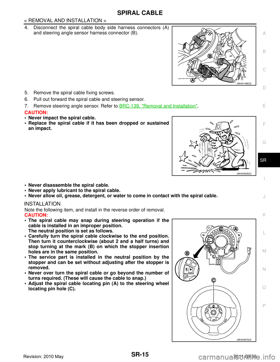
4. Disconnect the spiral cable body side harness connectors (A) and steering angle sensor harness connector (B).
5. Remove the spiral cable fixing screws.
6. Pull out forward the spiral cable and steering sensor.
7. Remove steering angle sensor. Refer to BRC-139, "
Removal and Installation".
CAUTION:
Never impact the spiral cable.
Replace the spiral cable if it has been dropped or sustained
an impact.
Never disassemble the spiral cable.
Never apply lubricant to the spiral cable.
Never allow oil, grease, detergent, or water to come in contact with the spiral cable.
INSTALLATION
Note the following item, and install in the reverse order of removal.
CAUTION:
The spiral cable may snap during steering operation if the
cable is installed in an improper position.
The neutral position is set as follows.
Carefully turn the spiral cable clockwise to the end position.
Then turn it counterclockwise (a bout 2 and a half turns) and
stop turning at the mark (B) on which the stopper insertion
holes are in the same position.
The service part is installed in the neutral position by the
stopper and can be set without adjusting after the stopper is
removed.
Never over turn the spiral cable or go beyond the number of
turns required. (These will cause the cable to snap.)
Adjust the spiral cable locatin g pin (A) to the steering wheel
locating pin hole (C).
JMHIA1486ZZ
JMHIA0009ZZ
JMHIA0879ZZ
Revision: 2010 May2011 QX56
Page 4794 of 5598

SRC-1
RESTRAINTS
C
DE
F
G
I
J
K L
M
SECTION SRC
A
B
SRC
N
O P
CONTENTS
SRS AIRBAG CONTROL SYSTEM
PRECAUTION ................ ...............................6
PRECAUTIONS .............................................. .....6
Precaution for Supplemental Restraint System
(SRS) "AIR BAG" and "SEAT BELT PRE-TEN-
SIONER" ............................................................. ......
6
Service ......................................................................6
SYSTEM DESCRIPTION ..............................8
COMPONENT PARTS ................................... .....8
Component Parts Location .................................. ......8
Component Description .............................................9
SYSTEM .............................................................11
System Diagram .................................................. ....11
System Description .................................................12
DIAGNOSIS SYSTEM (AIR BAG) .....................14
Description .......................................................... ....14
On Board Diagnosis Function .................................14
CONSULT-III Function ............................................19
DIAGNOSIS SYSTEM (OCCUPANT DETEC-
TION SYSTEM) .............................................. ....
21
CONSULT-III Function ........................................ ....21
ECU DIAGNOSIS INFORMATION ..............22
DIAGNOSIS SENSOR UNIT .......................... ....22
DTC Index .......................................................... ....22
WIRING DIAGRAM ......................................27
SRS AIR BAG SYSTEM ................................. ....27
Wiring Diagram ................................................... ....27
BASIC INSPECTION ...................................36
DIAGNOSIS AND REPAIR WORK FLOW .... ....36
Work Flow ........................................................... ....36
INSPECTION AND ADJUSTMENT ....................39
ADDITIONAL SERVICE WHEN REPLACING
CONTROL UNIT .................................................... ....
39
ADDITIONAL SERVICE WHEN REPLACING
CONTROL UNIT : Description .................................
39
ADDITIONAL SERVICE WHEN REPLACING
CONTROL UNIT : Special Repair Requirement ......
39
ZERO POINT RESET ............................................. ....39
ZERO POINT RESET : Description .........................39
ZERO POINT RESET : Special Repair Require-
ment .........................................................................
39
DTC/CIRCUIT DIAGNOSIS .........................41
B1001, B1002, B1003, B1004, B1005 DIAG-
NOSIS SENSOR UNIT ......................................
41
DTC Logic ............................................................ ....41
Diagnosis Procedure ...............................................41
B1006, B1007, B1008, B1009, B1010 DIAG-
NOSIS SENSOR UNIT ......................................
42
DTC Logic ................................................................42
Diagnosis Procedure ...............................................42
B1011, B1012, B1013, B1014, B1015 DIAG-
NOSIS SENSOR UNIT ......................................
43
DTC Logic ................................................................43
Diagnosis Procedure ...............................................43
B1017, B1020, B1021 OCCUPANT SENS C/U
...
44
Description ........................................................... ....44
DTC Logic ................................................................44
Diagnosis Procedure ...............................................44
B1018 OCCUPANT SENS ................................46
Description ........................................................... ....46
DTC Logic ................................................................46
Diagnosis Procedure ...............................................46
B1022 OCCUPANT SENS C/U .........................48
Description ...............................................................48
Revision: 2010 May2011 QX56
Page 4799 of 5598

SRC-6
< PRECAUTION >
PRECAUTIONS
PRECAUTION
PRECAUTIONS
Precaution for Supplemental Restraint System (SRS) "AIR BAG" and "SEAT BELT
PRE-TENSIONER"
INFOID:0000000006219946
The Supplemental Restraint System such as “A IR BAG” and “SEAT BELT PRE-TENSIONER”, used along
with a front seat belt, helps to reduce the risk or severi ty of injury to the driver and front passenger for certain
types of collision. This system includes seat belt switch inputs and dual stage front air bag modules. The SRS
system uses the seat belt switches to determine the front air bag deployment, and may only deploy one front
air bag, depending on the severity of a collision and w hether the front occupants are belted or unbelted.
Information necessary to service the system safely is included in the “SRS AIR BAG” and “SEAT BELT” of this
Service Manual.
WARNING:
• To avoid rendering the SRS inopera tive, which could increase the risk of personal injury or death in
the event of a collision that would result in air bag inflation, all maintenance must be performed by
an authorized NISS AN/INFINITI dealer.
Improper maintenance, including in correct removal and installation of the SRS, can lead to personal
injury caused by unintent ional activation of the system. For re moval of Spiral Cable and Air Bag
Module, see the “SRS AIR BAG”.
Do not use electrical test equipmen t on any circuit related to the SRS unless instructed to in this
Service Manual. SRS wiring harnesses can be identi fied by yellow and/or orange harnesses or har-
ness connectors.
PRECAUTIONS WHEN USING POWER TOOLS (AIR OR ELECTRIC) AND HAMMERS
WARNING:
When working near the Air Bag Diagnosis Sensor Unit or other Air Bag System sensors with the ignition ON or engine running, DO NOT use air or electric power tools or strike near the sensor(s)
with a hammer. Heavy vibration could activate the sensor(s) and deploy the air bag(s), possibly
causing serious injury.
When using air or electric power tools or hammers , always switch the ignition OFF, disconnect the
battery, and wait at least 3 minu tes before performing any service.
ServiceINFOID:0000000006219947
Never use electrical test equipment to check SRS circuits unless instructed to in this Service Manual.
Before servicing the SRS, turn ignition switch OF F, disconnect battery negative terminal and wait 3 minutes
or more.
For approximately 3 minutes after the cables are removed, it is still possible for the air bag and seat belt pre-
tensioner to deploy. Therefore, never work on any SR S connectors or wires until at least 3 minutes have
passed.
Diagnosis sensor unit must always be installed with their arrow marks “ ⇐” pointing towards the front of the
vehicle for proper operation. Also chec k diagnosis sensor unit for cracks, deformities or rust before installa-
tion and replace as required.
The spiral cable must be aligned with the neutral position since its rotations are limited. Never turn steering
wheel and column after removal of steering gear.
Handle air bag module carefully. Always place driver and front passenger air bag modules with the pad side facing upward and seat mounted front side air bag module standing with the stud bolt side facing down.
Conduct self-diagnosis to check entire SRS for proper function after replacing any components.
After air bag inflates, the front instrument panel assembly should be replaced if damaged.
Always replace instrument panel pad following front passenger air bag deployment.
Never solder the harness when making repairs. Check that harness is not pinched and that there is no con-
tact with other components.
Never allow harness to come in contact with oil, grease, waste oil, or water.
Never insert foreign materials, such as a screwdriver , into the harness connector. (This is to prevent acci-
dental activation caused by static electricity.)
Always use CONSULT-III or SRS air bag warning lamp to perform the circuit diagnosis. (Never use an elec- tric tester such as a circuit tester.)
Never enter in the deployment area of the pop-up roll bar. Never put an object in the deployment area of the
pop-up roll bar. (This is to prevent injury in case of an unintentional deployment.)
Revision: 2010 May2011 QX56
Page 4830 of 5598

DIAGNOSIS AND REPAIR WORK FLOWSRC-37
< BASIC INSPECTION >
C
DE
F
G
I
J
K L
M A
B
SRC
N
O P
1.INTERVIEW THE CUSTOMER FOR THE SYMPTOM
Interview the customer for the symptom (the condi tion and the environment when the incident/malfunction
occurs).
>> GO TO 2.
2.CHECK SYMPTOM
Check the symptom from the customer information.
>> GO TO 3.
3.CHECK WARNING LAMP OPERATION
Check air bag warning lamp operation in the user mode. Refer to SRC-14, "
On Board Diagnosis Function".
Are any malfunction detected?
YES >> GO TO 5.
NO >> GO TO 4.
4.CHECK LOW VOLTAGE
Check low voltage with CONSULT-III (Special function). Refer to SRC-19, "
CONSULT-III Function".
Are any malfunction detected?
YES >> GO TO 9.
NO >> Check intermittent incident. Refer to GI-40, "
Intermittent Incident".
5.CHECK SELF DIAGNOSTIC RESULTS
Check self diagnostic result with CONSULT-III or diagnosis mode.
If it is impossible to switch to diagnosis mode, follow the same pr ocedure that DTC is not detected.
NOTE:
Perform the following procedure if DTC is detected.
Record DTC (Print them out with CONSULT-III.)
Erase self diagnostic result.
Study the relationship between the malfunction that DT C or air bag warning lamp indicates and the symptom
that the customer describes.
Check related service bulletins for information.
Is DTC detected?
YES >> GO TO 6.
NO >> GO TO 7.
6.PERFORM DTC CONFIRMATION PROCEDURE
Perform DTC CONFIRMATION PROCEDURE for the DTC.
>> GO TO 8.
7.PERFORM DIAGNOSIS ACCORDING TO WARNING LAMP OPERATION
1. Check air bag warning lamp operation in the user mode. Refer to SRC-14, "
On Board Diagnosis Func-
tion".
2. Perform Diagnosis Procedure for the air bag warning lamp operation. Refer to SRC-14, "
On Board Diag-
nosis Function" (USER MODE).
>> GO TO 9.
8.DETECT MALFUNCTIONING PA RT BY DIAGNOSTIC PROCEDURE
Inspect according to Diagnostic Procedure of the DTC.
>> GO TO 9.
9.REPAIR OR REPLACE THE MALFUNCTION PART
Revision: 2010 May2011 QX56
Page 4832 of 5598

INSPECTION AND ADJUSTMENTSRC-39
< BASIC INSPECTION >
C
DE
F
G
I
J
K L
M A
B
SRC
N
O P
INSPECTION AND ADJUSTMENT
ADDITIONAL SERVICE WHEN REPLACING CONTROL UNIT
ADDITIONAL SERVICE WHEN REPL ACING CONTROL UNIT : Description
INFOID:0000000006219959
When replacing or removing and installing passenger seat, always perform zero point reset so that Occupant
Detection System is activated normally.
ADDITIONAL SERVICE WHEN REPLACING CONTROL UNIT : Special Repair Re-
quirement
INFOID:0000000006219960
WORK PROCEDURE WHEN REPLACING CONTROL UNIT
1.PERFORM ZERO POINT RESET
Perform zero point reset. Refer to SRC-39, "
ZERO POINT RESET : Special Repair Requirement".
>> END
ZERO POINT RESET
ZERO POINT RESET : DescriptionINFOID:0000000006219961
Zero point reset is an initializing procedure for occupant detection sensor that must be performed when replac-
ing or removing and installing passenger seat.
If zero point reset is not performed, the initializati on is incomplete and Occupant Detection System does not
operate normally.
NOTE:
When replacing passenger seat with a NISSAN genuine part, air bag warning lamp blinks if zero point reset
is incomplete.
When zero point reset is performed once after removal and installation of passenger seat, CONSULT-III dis-
plays “complete” and air bag warning does not blink.
When reinstalling passenger seat after removal, the initial value for occupant detection sensor changes, and
Occupant Detection System does not operate normally.
Always perform zero point reset after performing the work as per the following.
- Reinstallation of passenger seat
- Replacement of passenger seat with a seat that is zero point reset complete.
ZERO POINT RESET : Special Repair RequirementINFOID:0000000006219962
1.PERFORM ZERO POINT RESET
1. Perform zero point reset. NOTE:
When performing zero point reset, be careful of the items described as per the following.
Perform zero point reset after installing passenger seat to the vehicle
Do not put any objects on passenger seat
Do not apply excessive vibration to the vehicle
Do not touch the vehicle
Do not tilt the vehicle
2. Select start on “Zero point reset function” scr een from, WORK SUPPORT of CONSULT-III “OCCUPANT
DETECTION”.
3. “Zero point reset” starts.
>> GO TO 2.
2.CONFIRMATION OF SETTING
1. Proceed to “Zero point reset function” screen fr om work support of CONSULT-III “OCCUPANT DETEC-
TION”.
2. Check that “Complete” or “Incomplete” is displayed on “Zero point reset status”.
CAUTION:
Revision: 2010 May2011 QX56
Page 4988 of 5598

ST-1
STEERING
C
DE
F
H I
J
K L
M
SECTION ST
A
B
ST
N
O P
CONTENTS
STEERING SYSTEM
PRECAUTION ................ ...............................3
PRECAUTIONS .............................................. .....3
Precaution for Supplemental Restraint System
(SRS) "AIR BAG" and "SEAT BELT PRE-TEN-
SIONER" ............................................................. ......
3
Precaution Necessary for Steering Wheel Rota-
tion after Battery Disconnect .....................................
3
Service Notice or Precautions for Steering System
......
4
PREPARATION ............................................5
PREPARATION .............................................. .....5
Special Service Tools .......................................... ......5
Commercial Service Tools ........................................6
SYSTEM DESCRIPTION ..............................7
COMPONENT PARTS ................................... .....7
Component Parts Location (Heated Steering
Wheel) ................................................................. ......
7
Component Description (Heated Steering Wheel) ......7
Heated Steering Wheel .............................................7
Heated Steering Wheel Switch .................................8
Heated Steering Wheel Relay ...................................8
SYSTEM ..............................................................9
System Description (Heated Steering Wheel) ..... ......9
WIRING DIAGRAM ......................................10
HEATED STEERING WHEEL ........................ ....10
Wiring Diagram ................................................... ....10
BASIC INSPECTION ...................................13
DIAGNOSIS AND REPAIR WORK FLOW .... ....13
WorkFlow (Heated Steering Wheel) .................... ....13
STEERING WHEEL ............................................14
Inspection ............................................................ ....14
DTC/CIRCUIT DIAGNOSIS .........................16
HEATED STEERING WHEEL SYSTEM ...........16
Component Function Check ................................ ....16
Diagnosis Procedure ...............................................16
Component Inspection (Heated Steering Wheel) ....18
Component Inspection (Heated Steering Wheel
Relay) ......................................................................
19
HEATED STEERING WHEEL SWITCH INDI-
CATOR LAMP ...................................................
20
Component Function Check ....................................20
Diagnosis Procedure ...............................................20
Component Inspection (Heated Steering Wheel
Relay) ......................................................................
22
SYMPTOM DIAGNOSIS ..............................23
HEATED STEERING WHEEL SYSTEM DOES
NOT ACTIVATE ................................................
23
Description ........................................................... ....23
Diagnosis Procedure ...............................................23
HEATED STEERING WHEEL SWITCH INDI-
CATOR LAMP DOES NOT TURN ON ..............
26
Description ...............................................................26
Diagnosis Procedure ...............................................26
NOISE, VIBRATION AND HARSHNESS
(NVH) TROUBLESHOOTING ...........................
29
NVH Troubleshooting Chart ....................................29
PERIODIC MAINTENANCE ........................30
POWER STEERING FLUID ..............................30
Inspection ............................................................ ....30
STEERING WHEEL ..........................................32
Inspection ................................................................32
REMOVAL AND INSTALLATION ...............33
Revision: 2010 May2011 QX56
Page 4989 of 5598

ST-2
STEERING WHEEL ...........................................33
Exploded View ..................................................... ...33
Removal and Installation ........................................33
STEERING COLUMN ........................................34
Exploded View ..................................................... ...34
Removal and Installation ........................................34
Inspection ...............................................................35
STEERING SHAFT ............................................37
Exploded View ..................................................... ...37
Removal and Installation ........................................37
Inspection ...............................................................39
STEERING GEAR AND LINKAGE ....................41
Exploded View ..................................................... ...41
Removal and Installation ........................................42
Disassembly and Assembly ....................................43
Inspection ...............................................................46
POWER STEERING OIL PUMP ........................48
Exploded View ..................................................... ...48
Removal and Installation ........................................49
Disassembly and Assembly ....................................50
Inspection ...............................................................52
HYDRAULIC LINE .......................................... ...54
Exploded View ..................................................... ...54
HEATED STEERING WHEEL SWITCH ............56
Exploded View ..................................................... ...56
Removal and Installation .........................................56
SERVICE DATA AND SPECIFICATIONS
(SDS) .......... ................................................
57
SERVICE DATA AND SPECIFICATIONS
(SDS) .............................................................. ...
57
General Specifications ......................................... ...57
Steering Wheel Axial End Play and Play ................57
Steering Wheel Turning Force ................................57
Steering Angle ........................................................57
Steering Column Length .........................................57
Steering Column Mounting Dimensions ..................57
Steering Column Operating Range .........................57
Steering Shaft Sliding Range ..................................58
Rack Sliding Force ..................................................58
Rack Stroke ............................................................58
Socket Swing Force and Rotating Torque ..............58
Socket Axial End Play .............................................58
Inner Socket Length ................................................58
Relief Oil Pressure ..................................................58
Revision: 2010 May2011 QX56
Page 4990 of 5598

PRECAUTIONSST-3
< PRECAUTION >
C
DE
F
H I
J
K L
M A
B
ST
N
O P
PRECAUTION
PRECAUTIONS
Precaution for Supplemental Restraint System (SRS) "AIR BAG" and "SEAT BELT
PRE-TENSIONER"
INFOID:0000000006272045
The Supplemental Restraint System such as “A IR BAG” and “SEAT BELT PRE-TENSIONER”, used along
with a front seat belt, helps to reduce the risk or severi ty of injury to the driver and front passenger for certain
types of collision. This system includes seat belt switch inputs and dual stage front air bag modules. The SRS
system uses the seat belt switches to determine the front air bag deployment, and may only deploy one front
air bag, depending on the severity of a collision and whether the front occupants are belted or unbelted.
Information necessary to service the system safely is included in the “SRS AIR BAG” and “SEAT BELT” of this
Service Manual.
WARNING:
• To avoid rendering the SRS inoper ative, which could increase the risk of personal injury or death in
the event of a collision that would result in air ba g inflation, all maintenance must be performed by
an authorized NISSAN/INFINITI dealer.
Improper maintenance, including in correct removal and installation of the SRS, can lead to personal
injury caused by unintentional act ivation of the system. For removal of Spiral Cable and Air Bag
Module, see the “SRS AIR BAG”.
Do not use electrical test equipm ent on any circuit related to the SRS unless instructed to in this
Service Manual. SRS wiring harnesses can be identi fied by yellow and/or orange harnesses or har-
ness connectors.
PRECAUTIONS WHEN USING POWER TOOLS (AIR OR ELECTRIC) AND HAMMERS
WARNING:
When working near the Air Bag Diagnosis Sensor Unit or other Air Bag System sensors with the
ignition ON or engine running, DO NOT use air or electric power tools or strike near the sensor(s)
with a hammer. Heavy vibration could activate the sensor(s) and deploy the air bag(s), possibly
causing serious injury.
When using air or electric power tools or hammers , always switch the ignition OFF, disconnect the
battery, and wait at least 3 minutes before performing any service.
Precaution Necessary for Steering Wh eel Rotation after Battery Disconnect
INFOID:0000000006272046
NOTE:
Before removing and installing any control units, first tu rn the push-button ignition switch to the LOCK posi-
tion, then disconnect both battery cables.
After finishing work, confirm that all control unit connectors are connected properly, then re-connect both
battery cables.
Always use CONSULT-III to perform self-diagnosis as a part of each function inspection after finishing work.
If a DTC is detected, perform trouble diagnos is according to self-diagnosis results.
For vehicle with steering lock unit, if the battery is disconnected or discharged, the steering wheel will lock and
cannot be turned.
If turning the steering wheel is required with the batte ry disconnected or discharged, follow the operation pro-
cedure below before starting the repair operation.
OPERATION PROCEDURE
1. Connect both battery cables. NOTE:
Supply power using jumper cables if battery is discharged.
2. Turn the push-button ignition switch to ACC position. (At this time, the steering lock will be released.)
3. Disconnect both battery cables. The steering lock wil l remain released with both battery cables discon-
nected and the steering wheel can be turned.
4. Perform the necessary repair operation.
Revision: 2010 May2011 QX56