2011 INFINITI QX56 BATTERY
[x] Cancel search: BATTERYPage 3059 of 5598
PRECAUTIONSHA-3
< PRECAUTION >
C
DE
F
G H
J
K L
M A
B
HA
N
O P
PRECAUTION
PRECAUTIONS
Precaution for Supplemental Restraint System (SRS) "AIR BAG" and "SEAT BELT
PRE-TENSIONER"
INFOID:0000000006276136
The Supplemental Restraint System such as “A IR BAG” and “SEAT BELT PRE-TENSIONER”, used along
with a front seat belt, helps to reduce the risk or severi ty of injury to the driver and front passenger for certain
types of collision. This system includes seat belt switch inputs and dual stage front air bag modules. The SRS
system uses the seat belt switches to determine the front air bag deployment, and may only deploy one front
air bag, depending on the severity of a collision and whether the front occupants are belted or unbelted.
Information necessary to service the system safely is included in the “SRS AIR BAG” and “SEAT BELT” of this
Service Manual.
WARNING:
• To avoid rendering the SRS inoper ative, which could increase the risk of personal injury or death in
the event of a collision that would result in air ba g inflation, all maintenance must be performed by
an authorized NISSAN/INFINITI dealer.
Improper maintenance, including in correct removal and installation of the SRS, can lead to personal
injury caused by unintentional act ivation of the system. For removal of Spiral Cable and Air Bag
Module, see the “SRS AIR BAG”.
Do not use electrical test equipm ent on any circuit related to the SRS unless instructed to in this
Service Manual. SRS wiring harnesses can be identi fied by yellow and/or orange harnesses or har-
ness connectors.
PRECAUTIONS WHEN USING POWER TOOLS (AIR OR ELECTRIC) AND HAMMERS
WARNING:
When working near the Air Bag Diagnosis Sensor Unit or other Air Bag System sensors with the
ignition ON or engine running, DO NOT use air or electric power tools or strike near the sensor(s)
with a hammer. Heavy vibration could activate the sensor(s) and deploy the air bag(s), possibly
causing serious injury.
When using air or electric power tools or hammers , always switch the ignition OFF, disconnect the
battery, and wait at least 3 minutes before performing any service.
Precaution Necessary for Steering Wh eel Rotation after Battery Disconnect
INFOID:0000000006276137
NOTE:
Before removing and installing any control units, first tu rn the push-button ignition switch to the LOCK posi-
tion, then disconnect both battery cables.
After finishing work, confirm that all control unit connectors are connected properly, then re-connect both
battery cables.
Always use CONSULT-III to perform self-diagnosis as a part of each function inspection after finishing work.
If a DTC is detected, perform trouble diagnos is according to self-diagnosis results.
For vehicle with steering lock unit, if the battery is disconnected or discharged, the steering wheel will lock and
cannot be turned.
If turning the steering wheel is required with the batte ry disconnected or discharged, follow the operation pro-
cedure below before starting the repair operation.
OPERATION PROCEDURE
1. Connect both battery cables. NOTE:
Supply power using jumper cables if battery is discharged.
2. Turn the push-button ignition switch to ACC position. (At this time, the steering lock will be released.)
3. Disconnect both battery cables. The steering lock wil l remain released with both battery cables discon-
nected and the steering wheel can be turned.
4. Perform the necessary repair operation.
Revision: 2010 May2011 QX56
Page 3060 of 5598
HA-4
< PRECAUTION >
PRECAUTIONS
5. When the repair work is completed, re-connect both battery cables. With the brake pedal released, turn
the push-button ignition switch from ACC position to ON position, then to LOCK position. (The steering
wheel will lock when the push-button igniti on switch is turned to LOCK position.)
6. Perform self-diagnosis check of all control units using CONSULT-III.
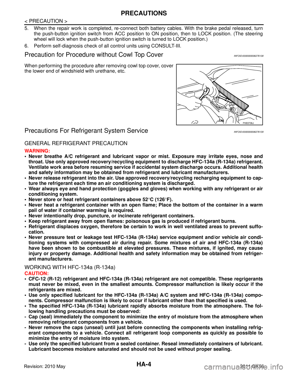
Precaution for Procedure without Cowl Top CoverINFOID:0000000006276138
When performing the procedure after removing cowl top cover, cover
the lower end of windshield with urethane, etc.
Precautions For Refrigerant System ServiceINFOID:0000000006276139
GENERAL REFRIGERANT PRECAUTION
WARNING:
Never breathe A/C refrigerant an d lubricant vapor or mist. Exposure may irritate eyes, nose and
throat. Use only approved reco very/recycling equipment to discharge HFC-134a (R-134a) refrigerant.
Ventilate work area before resuming service if acci dental system discharge occurs. Additional health
and safety information may be obtained from refrigerant and lubricant manufacturers.
Never release refrigerant into the air. Use appro ved recovery/recycling recharging equipment to cap-
ture the refrigerant each time an ai r conditioning system is discharged.
Wear always eye and hand protection (goggles and gloves) when working with any refrigerant or air
conditioning system.
Never store or heat refrigerant containers above 52 °C (126 °F).
Never heat a refrigerant container with an open flame; Place the bottom of the container in a warm
pail of water if container warming is required.
Never intentionally drop, puncture, or incinerate refrigerant containers.
Keep refrigerant away from open flames: pois onous gas is produced if refrigerant burns.
Refrigerant displaces oxygen, therefore be certain to work in well ventilated areas to prevent suffo-
cation.
Never pressure test or leakage test HFC-134a (R- 134a) service equipment and/or vehicle air condi-
tioning systems with compressed air during repair. Some mixtures of air and HFC-134a (R-134a)
have been shown to be combusti ble at elevated pressures. These mixtures, if ignited, may cause
injury or property damage. Additional health and safety information may be obtained from refriger-
ant manufacturers.
WORKING WITH HFC-134a (R-134a)
CAUTION:
CFC-12 (R-12) refrigerant and HFC-134a (R-134a) re frigerant are not compatible. These regrigerants
must never be mixed, even in the smallest amount s. Compressor malfunction is likely occur if the
refrigerants are mixed.
Use only specified lubricant for the HFC-134a (R-134a) A/C system and HFC-134a (R-134a) compo-
nents. Compressor malfunction is likely to occur if lubricant other than that specified is used.
The specified HFC-134a (R-134a) lu bricant rapidly absorbs moisture from the atmosphere. The fol-
lowing handling precauti ons must be observed:
- Cap (seal) immediately the compon ent to minimize the entry of moisture from the atmosphere when
removing refrigerant components from a vehicle.
- Never remove the caps (unseal) until just before co nnecting the components when installing refrig-
erant components to a vehicle. Connect all refr igerant loop components as quickly as possible to
minimize the entry of moisture into system.
- Use only the specified lubricant from a sealed contai ner. Reseal immediately containers of lubricant.
Lubricant becomes moisture saturated and should not be used without proper sealing.
PIIB3706J
Revision: 2010 May2011 QX56
Page 3065 of 5598
PREPARATIONHA-9
< PREPARATION >
C
DE
F
G H
J
K L
M A
B
HA
N
O P
PREPARATION
PREPARATION
Special Service ToolINFOID:0000000006276517
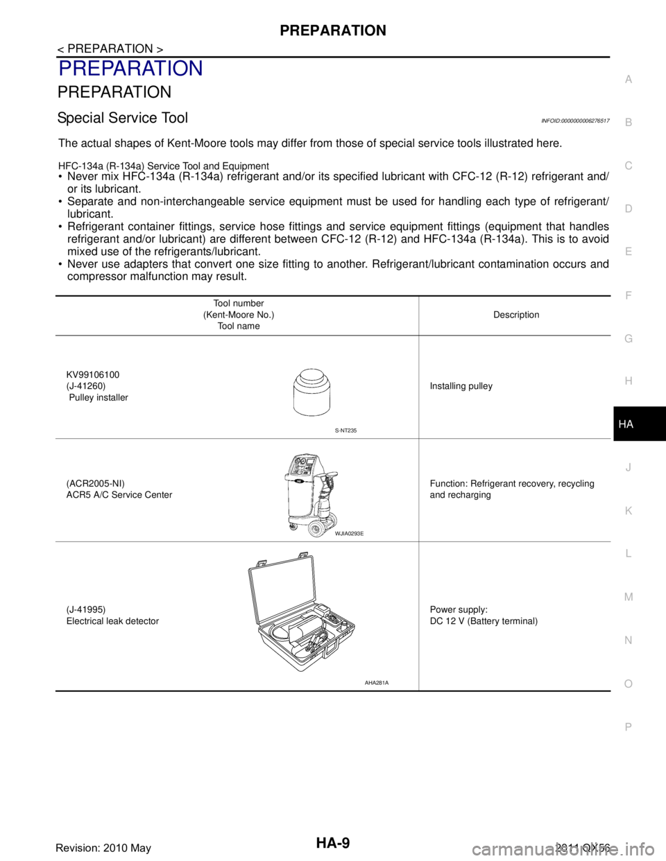
The actual shapes of Kent-Moore tools may differ fr om those of special service tools illustrated here.
HFC-134a (R-134a) Service Tool and Equipment
Never mix HFC-134a (R-134a) refrigerant and/or its spec ified lubricant with CFC-12 (R-12) refrigerant and/
or its lubricant.
Separate and non-interchangeable service equipment must be used for handling each type of refrigerant/
lubricant.
Refrigerant container fittings, service hose fittings and service equipment fittings (equipment that handles
refrigerant and/or lubricant) are different between CF C-12 (R-12) and HFC-134a (R-134a). This is to avoid
mixed use of the refrigerants/lubricant.
Never use adapters that convert one size fitting to another. Refrigerant/lubricant contamination occurs and
compressor malfunction may result.
Tool number
(Kent-Moore No.) Tool name Description
KV99106100
(J-41260)
Pulley installer Installing pulley
(ACR2005-NI)
ACR5 A/C Se rvice Center Function: Refrigerant recovery, recycling
and recharging
(J-41995)
Electrical leak detector Power supply:
DC 12 V (Battery terminal)
S-NT235
WJIA0293E
AHA281A
Revision: 2010 May2011 QX56
Page 3066 of 5598
HA-10
< PREPARATION >
PREPARATION
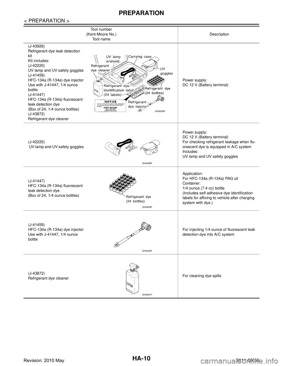
(J-43926)
Refrigerant dye leak detection
kit
Kit includes:
(J-42220)
UV lamp and UV safety goggles
(J-41459)
HFC-134a (R-134a) dye injector
Use with J-41447, 1/4 ounce
bottle
(J-41447)
HFC-134a (R-134a) fluorescent
leak detection dye
(Box of 24, 1/4 ounce bottles)
(J-43872)
Refrigerant dye cleanerPower supply:
DC 12 V (Battery terminal)
(J-42220)
UV lamp and UV safety goggles Power supply:
DC 12 V (Battery terminal)
For checking refrigerant leakage when flu-
orescent dye is equipped in A/C system
Includes:
UV lamp and UV safety goggles
(J-41447)
HFC-134a (R-134a) fluorescent
leak detection dye
(Box of 24, 1/4 ounce bottles) Application:
For HFC-134a (R-134a) PAG oil
Container:
1/4 ounce (7.4 cc) bottle
(Includes self-adhesive dye identification
labels for affixing to vehicle after charging
system with dye.)
(J-41459)
HFC-134a (R-134a) dye injector
Use with J-41447, 1/4 ounce
bottle For injecting 1/4 ounce of fluorescent leak
detection dye into A/C system
(J-43872)
Refrigerant dye cleaner For cleaning dye spills
Tool number
(Kent-Moore No.)
Tool name Description
ZHA200H
SHA438F
SHA439F
SHA440F
SHA441F
Revision: 2010 May2011 QX56
Page 3074 of 5598
HA-18
< BASIC INSPECTION >
REFRIGERANT
REFRIGERANT
DescriptionINFOID:0000000006276149
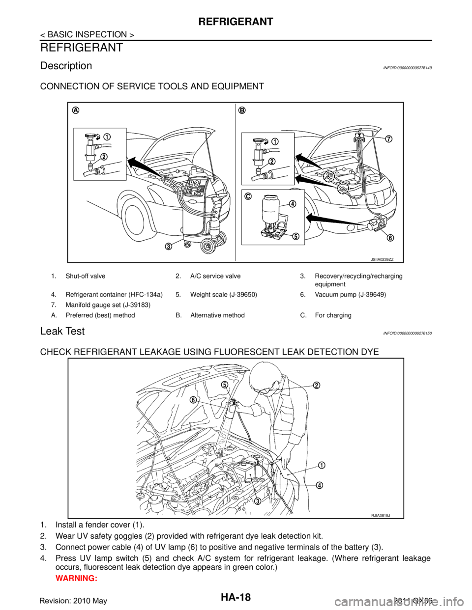
CONNECTION OF SERVICE TOOLS AND EQUIPMENT
Leak TestINFOID:0000000006276150
CHECK REFRIGERANT LEAKAGE USING FLUORESCENT LEAK DETECTION DYE
1. Install a fender cover (1).
2. Wear UV safety goggles (2) provided with refrigerant dye leak detection kit.
3. Connect power cable (4) of UV lamp (6) to positive and negative terminals of the battery (3).
4. Press UV lamp switch (5) and check A/C system for refrigerant leakage. (Where refrigerant leakage
occurs, fluorescent leak detec tion dye appears in green color.)
WARNING:
1. Shut-off valve 2. A/C service valve 3. Recovery/recycling/recharging equipment
4. Refrigerant container (HFC-134a) 5. Weight scale (J-39650) 6. Vacuum pump (J-39649)
7. Manifold gauge set (J-39183)
A. Preferred (best) method B. Alternative method C. For charging
JSIIA0239ZZ
RJIA3815J
Revision: 2010 May2011 QX56
Page 3091 of 5598
COOLER PIPE AND HOSEHA-35
< REMOVAL AND INSTALLATION >
C
DE
F
G H
J
K L
M A
B
HA
N
O P
Check for leakages when recharging refrigerant. Refer to HA-18, "Leak Test".
LOW-PRESSURE FLEXIBLE HOSE
LOW-PRESSURE FLEXIBLE HOSE : Removal and InstallationINFOID:0000000006276174
CAUTION:
Perform lubricant return operation before each refrigeration system disassembly. However, if a large
amount of refrigerant or lubricant is detected, n ever perform lubricant return operation. Refer to HA-
22, "Perform Lubricant Return Operation".
REMOVAL
1. Use a refrigerant collecting equipment (for HF C-B4a) to discharge the refrigerant. Refer to HA-22, "Per-
form Lubricant Return Operation".
2. Remove air cleaner. Refer to EM-27, "
Removal and Installation".
3. Remove the mounting bolt installed in low-pressure flexible hose from the vehicle.
4. Remove mounting bolts, and then remove low-pressure flexible hose from the vehicle. CAUTION:
Cap or wrap the joint of the A/C piping and comp ressor with suitable material such as vinyl tape to
avoid the entry of air.
INSTALLATION
Note the following items, and install in the reverse order of removal.
CAUTION:
Replace O-rings with new ones. Then apply compressor oil to them when installing.
Check for leakages when recharging refrigerant. Refer to HA-18, "
Leak Test".
HIGH-PRESSURE PIPE
HIGH-PRESSURE PIPE : Removal and InstallationINFOID:0000000006276175
CAUTION:
Perform lubricant return operati on before each refrigeration system disassembly. However, if a large
amount of refrigerant or lubricant is detected, n ever perform lubricant return operation. Refer to HA-
22, "Perform Lubricant Return Operation".
REMOVAL
1. Use a refrigerant collecting equipment (for HF C-134a) to discharge the refrigerant. Refer to HA-22, "Per-
form Lubricant Return Operation".
2. Remove low-pressure pipe. Refer to HA-36, "
LOW-PRESSURE PIPE : Removal and Installation".
3. Remove battery. Refer to PG-164, "
Removal and Installation".
4. Remove mounting bolts, and then remove battery bracket.
5. Disconnect harness connector, harness clip and ground harness for securing work space.
6. Remove mounting bolt, and then disconnec t high-pressure pipe from condenser.
CAUTION:
Cap or wrap the joint of the A/C piping and comp ressor with suitable material such as vinyl tape to
avoid the entry of air.
7. Remove high-pressure pipe mounting nut.
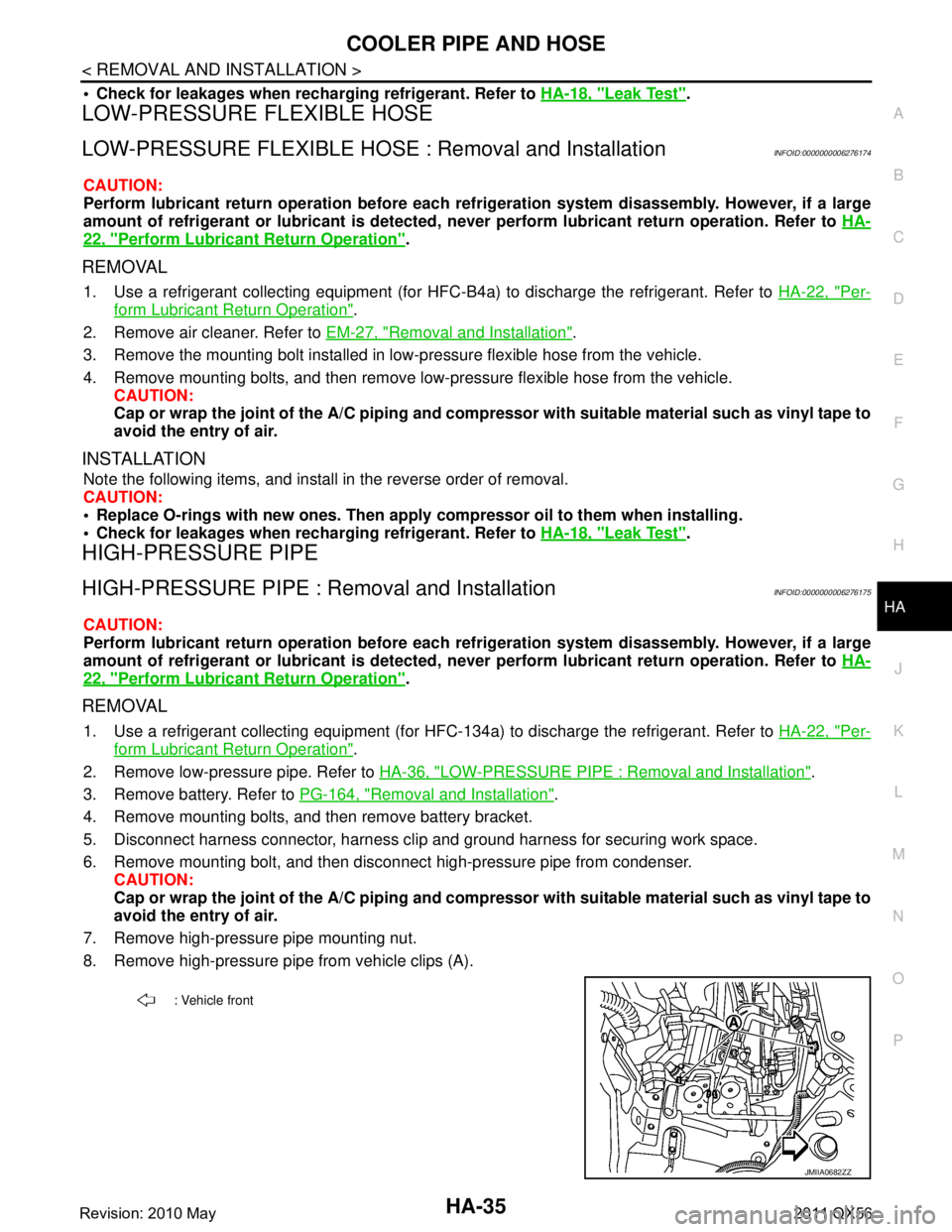
8. Remove high-pressure pipe from vehicle clips (A).
: Vehicle front
JMIIA0682ZZ
Revision: 2010 May2011 QX56
Page 3111 of 5598
![INFINITI QX56 2011 Factory Service Manual
PRECAUTIONSHAC-5
< PRECAUTION > [AUTOMATIC AIR CONDITIONING]
C
D
E
F
G H
J
K L
M A
B
HAC
N
O P
PRECAUTION
PRECAUTIONS
Precaution for Supplemental Restraint System (SRS) "AIR BAG" and "SEAT BELT
PRE INFINITI QX56 2011 Factory Service Manual
PRECAUTIONSHAC-5
< PRECAUTION > [AUTOMATIC AIR CONDITIONING]
C
D
E
F
G H
J
K L
M A
B
HAC
N
O P
PRECAUTION
PRECAUTIONS
Precaution for Supplemental Restraint System (SRS) "AIR BAG" and "SEAT BELT
PRE](/manual-img/42/57033/w960_57033-3110.png)
PRECAUTIONSHAC-5
< PRECAUTION > [AUTOMATIC AIR CONDITIONING]
C
D
E
F
G H
J
K L
M A
B
HAC
N
O P
PRECAUTION
PRECAUTIONS
Precaution for Supplemental Restraint System (SRS) "AIR BAG" and "SEAT BELT
PRE-TENSIONER"
INFOID:0000000006275847
The Supplemental Restraint System such as “A IR BAG” and “SEAT BELT PRE-TENSIONER”, used along
with a front seat belt, helps to reduce the risk or severi ty of injury to the driver and front passenger for certain
types of collision. This system includes seat belt switch inputs and dual stage front air bag modules. The SRS
system uses the seat belt switches to determine the front air bag deployment, and may only deploy one front
air bag, depending on the severity of a collision and whether the front occupants are belted or unbelted.
Information necessary to service the system safely is included in the “SRS AIR BAG” and “SEAT BELT” of this
Service Manual.
WARNING:
• To avoid rendering the SRS inoper ative, which could increase the risk of personal injury or death in
the event of a collision that would result in air ba g inflation, all maintenance must be performed by
an authorized NISSAN/INFINITI dealer.
Improper maintenance, including in correct removal and installation of the SRS, can lead to personal
injury caused by unintentional act ivation of the system. For removal of Spiral Cable and Air Bag
Module, see the “SRS AIR BAG”.
Do not use electrical test equipm ent on any circuit related to the SRS unless instructed to in this
Service Manual. SRS wiring harnesses can be identi fied by yellow and/or orange harnesses or har-
ness connectors.
PRECAUTIONS WHEN USING POWER TOOLS (AIR OR ELECTRIC) AND HAMMERS
WARNING:
When working near the Air Bag Diagnosis Sensor Unit or other Air Bag System sensors with the
ignition ON or engine running, DO NOT use air or electric power tools or strike near the sensor(s)
with a hammer. Heavy vibration could activate the sensor(s) and deploy the air bag(s), possibly
causing serious injury.
When using air or electric power tools or hammers , always switch the ignition OFF, disconnect the
battery, and wait at least 3 minutes before performing any service.
Revision: 2010 May2011 QX56
Page 3145 of 5598
![INFINITI QX56 2011 Factory Service Manual
DIAGNOSIS SYSTEM (HVAC)HAC-39
< SYSTEM DESCRIPTION > [AUTOMATIC AIR CONDITIONING]
C
D
E
F
G H
J
K L
M A
B
HAC
N
O P
DIAGNOSIS SYSTEM (HVAC)
DescriptionINFOID:0000000006275884
Air conditioning system INFINITI QX56 2011 Factory Service Manual
DIAGNOSIS SYSTEM (HVAC)HAC-39
< SYSTEM DESCRIPTION > [AUTOMATIC AIR CONDITIONING]
C
D
E
F
G H
J
K L
M A
B
HAC
N
O P
DIAGNOSIS SYSTEM (HVAC)
DescriptionINFOID:0000000006275884
Air conditioning system](/manual-img/42/57033/w960_57033-3144.png)
DIAGNOSIS SYSTEM (HVAC)HAC-39
< SYSTEM DESCRIPTION > [AUTOMATIC AIR CONDITIONING]
C
D
E
F
G H
J
K L
M A
B
HAC
N
O P
DIAGNOSIS SYSTEM (HVAC)
DescriptionINFOID:0000000006275884
Air conditioning system performs self-diagnosis, operat ion check, function diagnosis, and various settings
using diagnosis function of each control unit.
CONSULT-III FunctionINFOID:0000000006275885
CONSULT-III performs the following functions via CAN communication with A/C auto amp.
NOTE:
Diagnosis should be performed with engine running. D oor motor operation speeds become slower and NO
results may be returned even for normal operation if battery voltage drops below 12 V during self-diagnosis.
SELF-DIAGNOSIS RESULTS
Refer to HAC-45, "DTC Index".
DATA MONITOR
Display item list
ECU Diagnostic item
(CONSULT-III)
A/C auto amp. HVACSelf Diagnostic Result
Data Monitor
Active Test
Work support
AV c o n t r o l u n i t MULTI AV
Self Diagnostic Result
Multi AV system on board diagnosis function
ECM ENGINESelf Diagnostic Result
Data Monitor
IPDM E/R IPDM E/RSelf Diagnostic Result
Data Monitor
Auto active test
Diagnostic mode Description
Self diagnostic result Displays the diagnosis results judged by A/C auto amp.
Data monitor Displays the input/output signal of A/C auto amp.
Active test The signals used to activate each device are forcibly supplied from A/C auto amp.
Work support Changes the setting for each setting function.
ECU identification Displays the part number of A/C auto amp.
Monitor item [Unit] Description
AMB TEMP SEN [ °C ( °F)] Ambient sensor value converted from ambient sensor signal received from ambient sen-
sor
IN-VEH TEMP [ °C ( °F)] Front in-vehicle sensor value converted from front in-vehicle sensor signal received from
front in-vehicle sensor
INT TEMP SEN [ °C ( °F)] Intake sensor value converted from intake sensor signal received from intake sensor
SUNLOAD SEN [w/m
2]Sunload sensor value converted from sunload sensor signal (driver side) received from
sunload sensor
AMB SEN CAL [ °C ( °F)] Ambient temperature value calculated by A/C auto amp.
IN-VEH CAL [ °C ( °F)] In-vehicle temperature (front side) value calculated by A/C auto amp.
INT TEMP CAL [ °C ( °F)] Front evaporator fin temperature value calculated by A/C auto amp.
SUNL SEN CAL [w/m
2]Sunload value (driver side) calculated by A/C auto amp.
Revision: 2010 May2011 QX56