2011 INFINITI QX56 seat memory
[x] Cancel search: seat memoryPage 146 of 5598

SEAT MEMORY SWITCHADP-137
< REMOVAL AND INSTALLATION >
C
DE
F
G H
I
K L
M A
B
ADP
N
O P
SEAT MEMORY SWITCH
Removal and InstallationINFOID:0000000006248443
REMOVAL
CAUTION:
When removing and in stalling, use shop cloths to protect parts from damage.
1. Remove front door garnish (1). Refer to INT-14, "
Removal and
Installation".
2. Press pawls and remove seat memory switch (2) from front door garnish (1), with flat-bladed screw driver (A).
INSTALLATION
Install in the reverse order of removal.
CAUTION:
Be sure to clump the harness to the right place.
NOTE:
After installing the driver seat, perform additional service when removing battery negative terminal. Refer to
ADP-51, "
ADDITIONAL SERVICE WHEN REMOVING BATTERY NEGATIVE TERMINAL : Description".
: Pawl
JMJIA1817ZZ
Revision: 2010 May2011 QX56
Page 165 of 5598

AV
SYSTEMAV-17
< SYSTEM DESCRIPTION >
C
DE
F
G H
I
J
K L
M B A
O P
Operating signal is transmitted to AV control unit wit h AV communication when it is operated by multifunction
switch or preset switch. The disk ejection operating signal is performed by hardwire.
Operating signal is transmitted to AV control unit with steering switch signal when it is operated by steering
switch.
Screen Display
Switching of display is performed with serial comm unication between front display unit and AV control unit.
AM/FM Radio Mode
AM/FM radio tuner is built into AV control unit.
AM/FM radio wave is received by radio antenna, next it is amplified by antenna amp., and finally it is input to
AV control unit.
FM radio wave is received by FM sub antenna, and it is transmitted to the AV control unit directly.
Audio signal is input to BOSE amp. and BOSE amp. outputs to each speaker.
Satellite Radio Mode
Satellite radio tuner is built into AV control unit.
Sound signal (satellite radio) is received by satel lite radio antenna and transmitted to AV control unit. AV
control unit outputs sound signal to BOSE amp. The si gnal is also outputted from BOSE amp. to each
speaker.
CD Mode
CD function is built into AV control unit.
AV control unit outputs audio signal to BOSE amp., and BOSE amp. outputs to each speaker when CD is
inserted to AV control unit.
Bluetooth™ Audio Mode
Bluetooth™ audio function is built into AV control unit.
Bluetooth
™ audio can play music data in the portable audio by means of Bluetooth™ communications
between the portable audio and the AV control unit.
AV control unit outputs audio signal to BOSE amp., and BOSE amp. outputs to each speaker.
Music Box Mode
Music CD data is stored on HDD that is built into AV control unit, and it can be played.
AV control unit outputs music (sound signal) that is stored on HDD to BOSE amp., and BOSE amp. outputs
to each speaker.
Speed Sensitive Volume
Volume level of this system gone up and down autom atically in proportion to the vehicle speed.
The control level can be selected by the customer.
Driver's Audio Stage
Driver's Audio Stage controls the speaker's output characte ristic by BOSE amp. so that the driver's seat is to
be the center of sounds.
ON/OFF signals of Driver's Audio Stage are transmitt ed from AV control unit to BOSE amp. using mode
change signal.
DVD PLAY FUNCTION
DVD is played by inserting DVD into the AV control unit.
DVD image signals are transmitted to the front display unit, and DVD sound signals are transmitted to each
speaker via BOSE amp.
DVD image signals and sound signals are transmitted to the headrest display unit via the video distributor.
The headrest display unit transmits the sound signals to the headphone via infrared communication.
USB CONNECTION FUNCTION
Connecting iPod® or USB memory allows the driver to play iPod® music files or USB memory-stored music
files, video data, and image viewer data.
Sound signals of music files stored in iPod
® or USB memory are transmitted from the USB connector to the
AV control unit. The AV control unit transmits t he sound signals to the BOSE amp. and video distributor.
Sound signals transmitted from the BOSE amp. to each speaker, and sound signals transmitted from the
video distributor to headphone via headrest display unit
Video signals and image viewer file signals are transmitt ed from the USB connector to the AV control unit.
The data and files are displayed on the front display unit screen.
Revision: 2010 May2011 QX56
Page 166 of 5598

AV-18
< SYSTEM DESCRIPTION >
SYSTEM
Video signals are transmitted from the USB connector to the AV control unit. The data and files are displayed
on the headrest display unit screen.
iPod
® is recharged when connected to USB connector.
Only files that meet the following conditions will be played.
NOTE:
iPod
® is a trademark of Apple inc., regist ered in the U.S. and other countries.
Image signals cannot be received from iPod
®.
Use the enclosed USB harness when connecting iPod
® to USB connector.
If a video-sound codec combination is not satisfied, its video file may not be played.
Signals cannot be transmitted to video dist ributor under the following conditions:
- Only sound signal or only image viewer data is stored in iPod
®
- Only sound signal or only image viewer data is stored in USB memory
FRONT AUXILIARY INPUT FUNCTION
Image and sound can be output from an external devic e by connecting a device with front auxiliary input
jacks.
AUX image signals are transmitted to each unit as follows:
- To the front display unit via AV control unit.
- To the headrest display unit via AV control unit and video distributor.
AUX sound signals are transmitted to each unit as follows:
- To each speaker via AV control unit and BOSE amp.
- To the video distributor via AV control unit, and headphone sound signals are transmitted to infrared commu-
nication between headrest display unit and headphone.
MOBILE ENTERTAINMENT SYSTEM
Image and sound (DVD, USB memory-stored video data and front auxiliary input) played by AV control unit can be enjoyed in rear seat using headrest display unit and headphone.
Image and sound of external device connected to rear aux iliary input jacks for rear seat can be enjoyed in
rear seat using headrest display unit and headphone. Al so, image and sound from rear auxiliary input jacks
can be selected and played individually on each side as well as on both sides.
Headrest display unit has the self-diagnosis function. Refer to AV-49, "
On Board Diagnosis Function".
NOTE:
Image signal and sound signal from rear auxiliary input ja cks is not transmitted to front display unit and each
speaker.
Operating Signal
The mobile entertainment system can be controlled by one of the rear seat remote controller.
It receives the operation signal of the rear seat remote controller by the remote control receiver built into
headrest display unit, and then transmits it to the AV control unit and the video distributor.
Headphone Sound
Sound signal output from AV control unit or rear auxilia ry input jacks are transmitted to headrest display unit
via video distributor.
Headphone sound signals are transmitted to infrared communication between headrest display unit and
headphone.
Screen headrest display
Image signal output from AV control unit or rear auxili ary input jacks are transmitted to headrest display unit
via video distributor.
Image switch signal is input from headrest display uni t to AV control unit or from headrest display unit to
video distributor, according to rear seat remote controller operation.
When image switch signal is transmitted from headrest display unit to AV control unit via AV communication,
image played by AV control unit (DVD, USB memory-sto red video data, and front auxiliary input) switches.
When image switch signal is input from headrest displa y unit to video distributor via hard wire, image output
from AV control unit and image output from rear auxiliary input jacks switch.
Music file Video file Image viewer file
File format “MP3”, “WMA”, “AAC”, “M4A” “DivX”, “MPEG4 (ASF)” “JPEG”
File extension “.mp3”, “.wma”, “.aac”, “.m4 a” “.divx”, “.afs”, “.avi” “.jpg”, “.jpeg”
Maximum file size 2 GB 2 GB 2 MB
Revision: 2010 May2011 QX56
Page 3362 of 5598
FRONT DOOR FINISHERINT-13
< REMOVAL AND INSTALLATION >
C
DE
F
G H
I
K L
M A
B
INT
N
O P
REMOVAL AND INSTALLATION
FRONT DOOR FINISHER
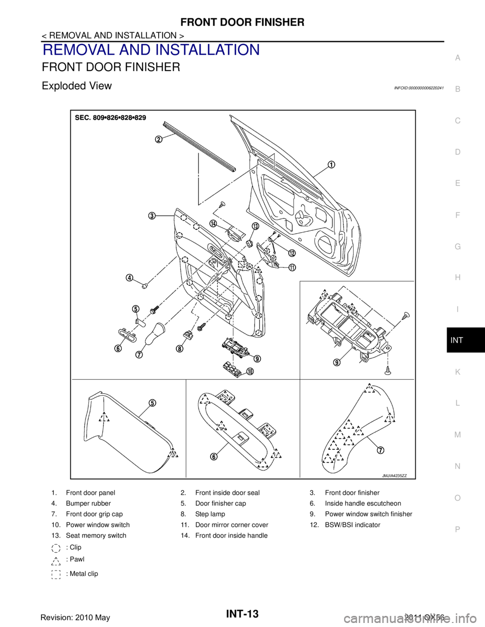
Exploded ViewINFOID:0000000006220241
1. Front door panel 2. Front inside door seal 3. Front door finisher
4. Bumper rubber 5. Door finisher cap 6. Inside handle escutcheon
7. Front door grip cap 8. Step lamp 9. Power window switch finisher
10. Power window switch 11. Door mirror corner cover 12. BSW/BSI indicator
13. Seat memory switch 14. Front door inside handle : Clip
: Pawl
: Metal clip
JMJIA4235ZZ
Revision: 2010 May2011 QX56
Page 3363 of 5598
INT-14
< REMOVAL AND INSTALLATION >
FRONT DOOR FINISHER
Removal and Installation
INFOID:0000000006220242
CAUTION:
When removing, always use a remover tool that is made of plastic.
Never damage the body.
REMOVAL
1. Fully open door window.
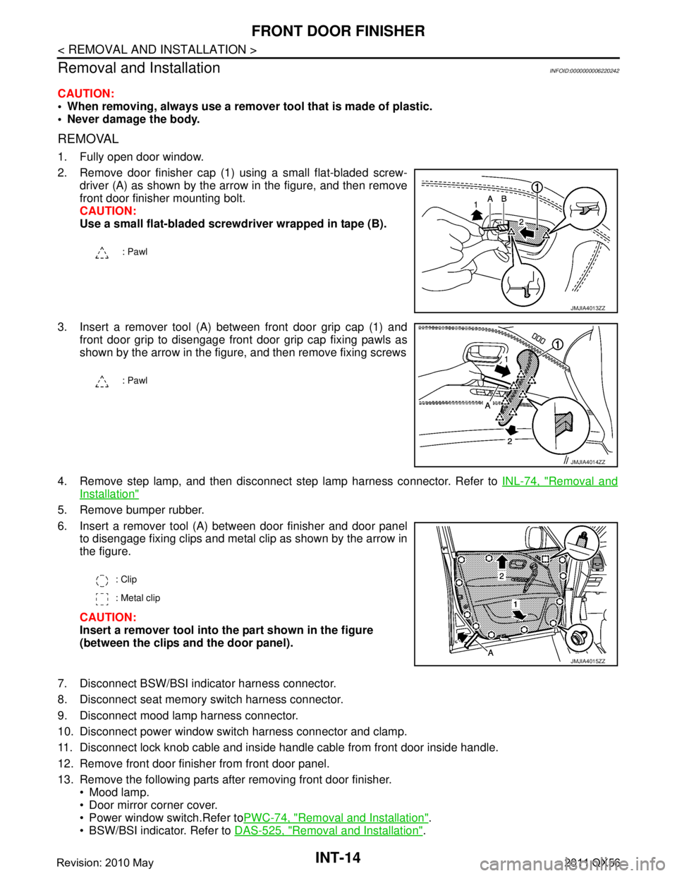
2. Remove door finisher cap (1) using a small flat-bladed screw- driver (A) as shown by the ar row in the figure, and then remove
front door finisher mounting bolt.
CAUTION:
Use a small flat-bladed screwdriver wrapped in tape (B).
3. Insert a remover tool (A) between front door grip cap (1) and front door grip to disengage front door grip cap fixing pawls as
shown by the arrow in the figure, and then remove fixing screws
4. Remove step lamp, and then disconnect step lamp harness connector. Refer to INL-74, "
Removal and
Installation"
5. Remove bumper rubber.
6. Insert a remover tool (A) between door finisher and door panel
to disengage fixing clips and metal clip as shown by the arrow in
the figure.
CAUTION:
Insert a remover tool into th e part shown in the figure
(between the clips an d the door panel).
7. Disconnect BSW/BSI indicator harness connector.
8. Disconnect seat memory switch harness connector.
9. Disconnect mood lamp harness connector.
10. Disconnect power window switch harness connector and clamp.
11. Disconnect lock knob cable and inside handle cable from front door inside handle.
12. Remove front door finisher from front door panel.
13. Remove the following parts after removing front door finisher. Mood lamp.
Door mirror corner cover.
Power window switch.Refer to PWC-74, "
Removal and Installation".
BSW/BSI indicator. Refer to DAS-525, "
Removal and Installation".
: Pawl
JMJIA4013ZZ
: Pawl
JMJIA4014ZZ
: Clip
: Metal clip
JMJIA4015ZZ
Revision: 2010 May2011 QX56
Page 3364 of 5598
FRONT DOOR FINISHERINT-15
< REMOVAL AND INSTALLATION >
C
DE
F
G H
I
K L
M A
B
INT
N
O P
Seat memory switch. Refer to ADP-137, "Removal and Installation".
Front door inside handle. Refer to DLK-241, "
INSIDE HANDLE : Removal and Installation".
INSTALLATION
Note the following items, and install in the reverse order of removal.
CAUTION:
Visually check the clips, pawls an d metal clip for deformation and damage during installation.
Replace with new ones if necessary.
When installing fron t door finisher, check that clips, pawls and metal clip are securely fitted in body
panel holes, and press them in.
Revision: 2010 May2011 QX56
Page 4308 of 5598
DIAGNOSIS SYSTEM (PRE-CRASH SEAT BELT)SBC-11
< SYSTEM DESCRIPTION >
C
DE
F
G
I
J
K L
M A
B
SBC
N
O P
DIAGNOSIS SYSTEM (P RE-CRASH SEAT BELT)
CONSULT-III FunctionINFOID:0000000006237882
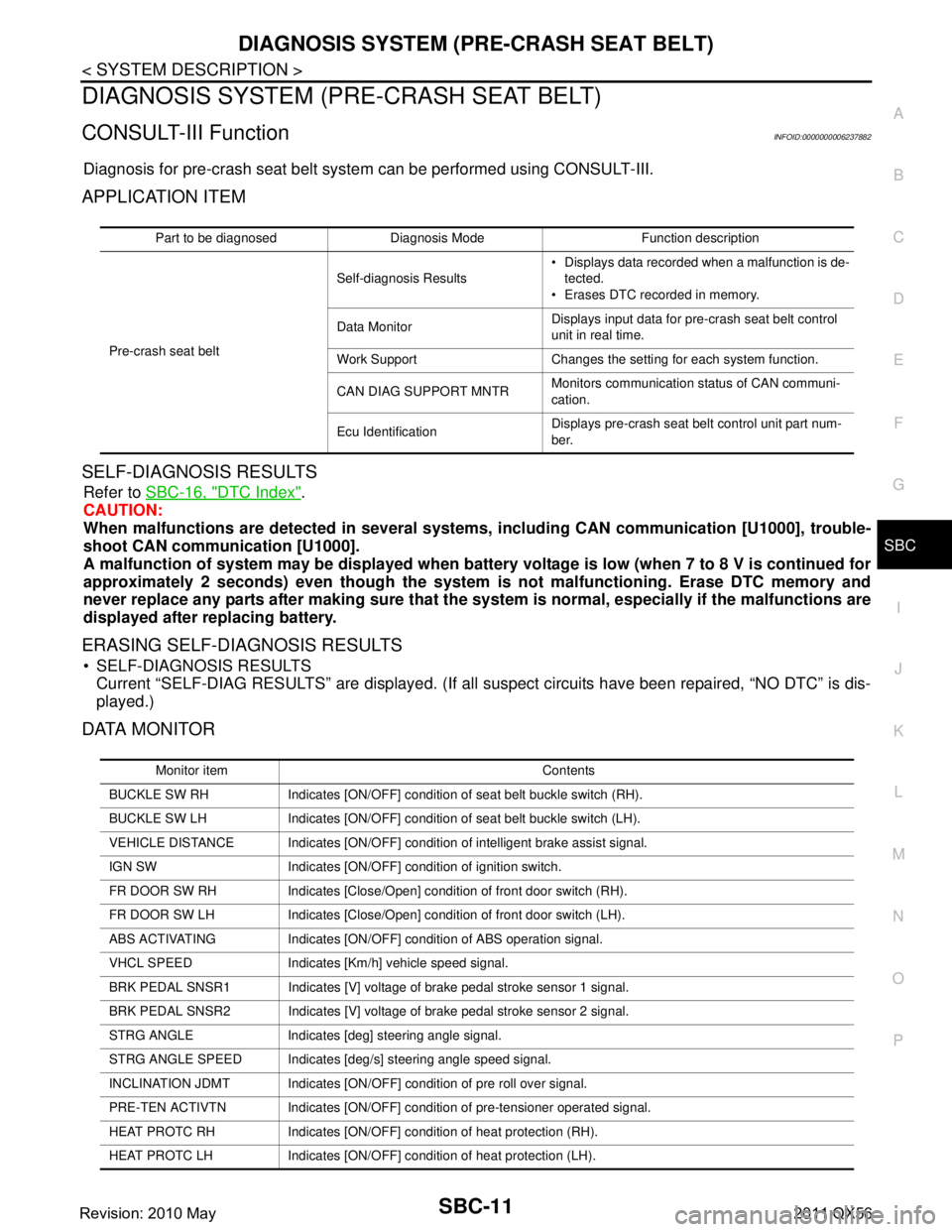
Diagnosis for pre-crash seat belt syst em can be performed using CONSULT-III.
APPLICATION ITEM
SELF-DIAGNOSIS RESULTS
Refer to SBC-16, "DTC Index".
CAUTION:
When malfunctions are detect ed in several systems, includin g CAN communication [U1000], trouble-
shoot CAN communication [U1000].
A malfunction of system may be disp layed when battery voltage is low (when 7 to 8 V is continued for
approximately 2 seconds) even though the system is not malfunctioning. Erase DTC memory and
never replace any parts after making sure that the syst em is normal, especially if the malfunctions are
displayed after replacing battery.
ERASING SELF-DIAGNOSIS RESULTS
SELF-DIAGNOSIS RESULTS Current “SELF-DIAG RESULTS” are displayed. (If all suspect circuits have been repaired, “NO DTC” is dis-
played.)
DATA MONITOR
Part to be diagnosed Diagnosis Mode Function description
Pre-crash seat belt Self-diagnosis Results
Displays data recorded when a malfunction is de-
tected.
Erases DTC recorded in memory.
Data Monitor Displays input data for pre-crash seat belt control
unit in real time.
Work Support Changes the setting for each system function.
CAN DIAG SUPPORT MNTR Monitors communication status of CAN communi-
cation.
Ecu Identification Displays pre-crash seat belt control unit part num-
ber.
Monitor item Contents
BUCKLE SW RH Indicates [ON/OFF] condition of seat belt buckle switch (RH).
BUCKLE SW LH Indicates [ON/OFF] condition of seat belt buckle switch (LH).
VEHICLE DISTANCE Indicates [ON/OFF] condit ion of intelligent brake assist signal.
IGN SW Indicates [ON/OFF] condition of ignition switch.
FR DOOR SW RH Indicates [Close/Open] condition of front door switch (RH).
FR DOOR SW LH Indicates [Close/Open] condition of front door switch (LH).
ABS ACTIVATING Indicates [ON/OFF] co ndition of ABS operation signal.
VHCL SPEED Indicates [Km/h] vehicle speed signal.
BRK PEDAL SNSR1 Indicates [V] voltage of brake pedal stroke sensor 1 signal.
BRK PEDAL SNSR2 Indicates [V] voltage of brake pedal stroke sensor 2 signal.
STRG ANGLE Indicates [deg] steering angle signal.
STRG ANGLE SPEED Indicates [deg/s] steering angle speed signal.
INCLINATION JDMT Indicates [ON/OFF] condition of pre roll over signal.
PRE-TEN ACTIVTN Indicates [ON/OFF] condition of pre-tensioner operated signal.
HEAT PROTC RH Indicates [ON/OFF] condition of heat protection (RH).
HEAT PROTC LH Indicates [ON/OFF] condition of heat protection (LH).
Revision: 2010 May2011 QX56
Page 4788 of 5598
SIDE AIR BAG (SATELLITE) SENSOR
SR-25
< REMOVAL AND INSTALLATION >
C
D E
F
G
I
J
K L
M A
B
SR
N
O P
2. Remove the front seat belt retractor. Refer to SB-6, "SEAT BELT RETRACTOR : Removal and Installa-
tion".
3. Remove the side air bag front (satellite) sensor RH fixing nut.
4. Disconnect the side air bag front (satellite) sens or RH harness connector, and then remove side air bag
front (satellite) sensor RH.
SIDE AIR BAG REAR (SATELLITE) SENSOR LH
1. Remove the luggage side lower finisher LH. Refer to INT-36, "LUGGAGE SIDE LOWER FINISHER :
Removal and Installation".
2. Remove the side air bag rear (satellite) sensor LH fixing nut.
3. Disconnect the side air bag rear (satellite) sensor LH harness connector, and then remove side air bag
rear (satellite) sensor LH.
SIDE AIR BAG REAR (SATELLITE) SENSOR RH
1. Remove the luggage side lower finisher RH. Refer to INT-36, "LUGGAGE SIDE LOWER FINISHER :
Removal and Installation".
2. Remove the shield bracket fixing screw, and then remove shield bracket.
3. Remove the side air bag rear (satellite) sensor RH fixing nut.
4. Disconnect the side air bag rear (satellite) sensor RH harness connector, and then remove side air bag rear (satellite) sensor RH.
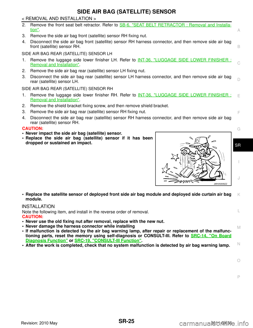
CAUTION:
Never impact the side air bag (satellite) sensor.
Replace the side air bag (sat ellite) sensor if it has been
dropped or sustained an impact.
Replace the satellite sensor of deployed front side air bag module and deployed side curtain air bag
module.
INSTALLATION
Note the following item, and install in the reverse order of removal.
CAUTION:
Never use the old fixing nut afte r removal, replace with the new nut.
Never damage the harness connector while installing
If malfunction is detected by the air bag warnin g lamp, after repair or replacement of the malfunc-
tioning parts, reset the memory using sel f-diagnosis or CONSULT-III. Refer to SRC-14, "
On Board
Diagnosis Function" or SRC-19, "CONSULT-III Function".
After the work is completed, check that no system malfunction is detected by air bag warning lamp.
JMHIA0009ZZ
Revision: 2010 May2011 QX56