2011 INFINITI QX56 brake rotor
[x] Cancel search: brake rotorPage 565 of 5598
![INFINITI QX56 2011 Factory Service Manual
BRC-48
< ECU DIAGNOSIS INFORMATION >[WITH VDC]
ABS ACTUATOR AND ELECTRIC UNIT (CONTROL UNIT)
VDC function, TCS function, hill start assist function and
brake limited slip differential (BLSD) functio INFINITI QX56 2011 Factory Service Manual
BRC-48
< ECU DIAGNOSIS INFORMATION >[WITH VDC]
ABS ACTUATOR AND ELECTRIC UNIT (CONTROL UNIT)
VDC function, TCS function, hill start assist function and
brake limited slip differential (BLSD) functio](/manual-img/42/57033/w960_57033-564.png)
BRC-48
< ECU DIAGNOSIS INFORMATION >[WITH VDC]
ABS ACTUATOR AND ELECTRIC UNIT (CONTROL UNIT)
VDC function, TCS function, hill start assist function and
brake limited slip differential (BLSD) function. How-
ever, ABS function and EBD function are operated normally.
ABS FUNCTION
ABS warning lamp and VDC warning lamp in combinati on meter turn ON when a malfunction occurs in system
[ABS actuator and electric unit (control unit)]. The c ontrol is suspended for VDC function, TCS function, ABS
function, hill start assist function and brake limited sl ip differential (BLSD) function. The vehicle status
becomes the same as models without VDC function, TCS f unction, ABS function, hill start assist function and
brake limited slip differential (BLSD) function. However, EBD function is operated normally.
NOTE:
ABS self-diagnosis sound may be heard the same as in the normal condition, because self-diagnosis is per-
formed when ignition switch turns ON and when vehicle initially starts.
EBD FUNCTION
ABS warning lamp, brake warning lamp and VDC warning lamp in combination meter turn ON when a mal-
function occurs in system [ABS actuator and electric unit (control unit)]. The control is suspended for VDC
function, TCS function, ABS function, EBD function, hill start assist function and brake limited slip differential
(BLSD) function. The vehicle status becomes the sa me as models without VDC function, TCS function, ABS
function, EBD function, hill star t assist function and brake limited slip differential (BLSD) function.
DTC Malfunction detected condition Fail-safe condition
C1101 When an open circuit is detected in rear RH wheel sensor circuit.
The following functions are sus-
pended.
VDC function
TCS function
ABS function
EBD function (only when both 2 rear wheels are malfunctioning)
hill start assist function
Brake limited slip differential (BLSD) function
C1102 When an open circuit is detected in rear LH wheel sensor circuit.
C1103 When an open circuit is detected in front RH wheel sensor circuit.
C1104 When an open circuit is detected in front LH wheel sensor circuit.
C1105
When power supply voltage of rear RH wheel sensor is low.
When distance between rear RH wheel sensor and rear RH wheel sensor rotor is
large.
When installation of rear RH wheel sensor or rear RH wheel sensor rotor is not normal.
C1106 When power supply voltage of rear LH wheel sensor is low.
When distance between rear LH wheel sensor and rear LH wheel sensor rotor is
large.
When installation of rear LH wheel sensor or rear LH wheel sensor rotor is not nor-
mal.
C1107 When power supply voltage of front RH wheel sensor is low.
When distance between front RH wheel sensor and front RH wheel sensor rotor
is large.
When installation of front RH wheel sensor or front RH wheel sensor rotor is not normal.
C1108 When power supply voltage of front LH wheel sensor is low.
When distance between front LH wheel sensor and front LH wheel sensor rotor is
large.
When installation of front LH wheel sensor or front LH wheel sensor rotor is not normal.
C1109 When ignition voltage is 10 V or less.
When ignition voltage is 16 V or more. The following functions are sus-
pended.
VDC function
TCS function
ABS function
EBD function
hill start assist function
Brake limited slip differential
(BLSD) function
C 1111
When a malfunction is detected in motor or motor relay.
When a low pressure malfunction is detected in accumulator.
When a malfunction is detected in accumulator pressure sensor.
Revision: 2010 May2011 QX56
Page 645 of 5598
![INFINITI QX56 2011 Factory Service Manual
BRC-128
< SYMPTOM DIAGNOSIS >[WITH VDC]
UNEXPECTED BRAKE PEDAL REACTION
UNEXPECTED BRAKE PEDAL REACTION
DescriptionINFOID:0000000006222659
A malfunction of brake pedal feel (height or ot
hers) is det INFINITI QX56 2011 Factory Service Manual
BRC-128
< SYMPTOM DIAGNOSIS >[WITH VDC]
UNEXPECTED BRAKE PEDAL REACTION
UNEXPECTED BRAKE PEDAL REACTION
DescriptionINFOID:0000000006222659
A malfunction of brake pedal feel (height or ot
hers) is det](/manual-img/42/57033/w960_57033-644.png)
BRC-128
< SYMPTOM DIAGNOSIS >[WITH VDC]
UNEXPECTED BRAKE PEDAL REACTION
UNEXPECTED BRAKE PEDAL REACTION
DescriptionINFOID:0000000006222659
A malfunction of brake pedal feel (height or ot
hers) is detected when brake pedal is depressed.
Diagnosis ProcedureINFOID:0000000006222660
1.CHECK FRONT AND REAR AXLE
Check that there is no excessive looseness in front and rear axle.
Front axle: Refer to FAX-7, "
Inspection" (2WD), FAX-16, "Inspection" (4WD).
Rear axle: Refer to RAX-5, "
Inspection"
Is the inspection result normal?
YES >> GO TO 2.
NO >> Repair or replace error-detected parts.
2.CHECK DISC ROTOR
Check disc rotor runout.
Front: Refer to BR-16, "
DISC ROTOR : Inspection and Adjustment".
Rear: Refer to BR-18, "
DISC ROTOR : Inspection and Adjustment".
Is the inspection result normal?
YES >> GO TO 3.
NO >> Refinish or replace disc rotor. Front: Refer to BR-16, "
DISC ROTOR : Inspection and Adjustment".
Rear: Refer to BR-18, "
DISC ROTOR : Inspection and Adjustment".
3.CHECK BRAKE FLUID LEACKAGE
Check fluid leakage.
Front: Refer to BR-24, "
FRONT : Inspection".
Rear: Refer to BR-26, "
REAR : Inspection".
Is the inspection result normal?
YES >> GO TO 4.
NO >> Repair or replace error-detected parts.
4.CHECK BRAKE PEDAL
Check each item of brake pedal. Refer to BR-7, "
Inspection and Adjustment".
Is the inspection result normal?
YES >> GO TO 5.
NO >> Adjust each item of brake pedal. Refer to BR-7, "
Inspection and Adjustment".
5.CHECK BRAKING FORCE
Check brake force using a brake tester.
Is the inspection result normal?
YES >> GO TO 6.
NO >> Check each components of brake system.
6.CHECK BRAKE PERFORMANCE
Disconnect ABS actuator and electric unit (control unit) connector so that ABS does not operate. Check that
brake force is normal in this condition. Connect harness connectors after checking.
Is the inspection result normal?
YES >> Normal
NO >> Check each components of brake system.
Revision: 2010 May2011 QX56
Page 2908 of 5598
![INFINITI QX56 2011 Factory Service Manual
FAX-8
< REMOVAL AND INSTALLATION >[2WD]
FRONT WHEEL HUB AND KNUCKLE
REMOVAL AND INSTALLATION
FRONT WHEEL HUB AND KNUCKLE
Exploded ViewINFOID:0000000006225418
Removal and InstallationINFOID:0000000006 INFINITI QX56 2011 Factory Service Manual
FAX-8
< REMOVAL AND INSTALLATION >[2WD]
FRONT WHEEL HUB AND KNUCKLE
REMOVAL AND INSTALLATION
FRONT WHEEL HUB AND KNUCKLE
Exploded ViewINFOID:0000000006225418
Removal and InstallationINFOID:0000000006](/manual-img/42/57033/w960_57033-2907.png)
FAX-8
< REMOVAL AND INSTALLATION >[2WD]
FRONT WHEEL HUB AND KNUCKLE
REMOVAL AND INSTALLATION
FRONT WHEEL HUB AND KNUCKLE
Exploded ViewINFOID:0000000006225418
Removal and InstallationINFOID:0000000006225419
REMOVAL
1. Remove tires with power tool. Refer to
WT-64, "Removal and Installation".
2. Remove brake hose bracket. Refer to BR-23, "
FRONT : Removal and Installation".
3. Remove caliper assembly mounting bolts. Hang caliper assembly in a place where it will not interfere with work. Refer to BR-37, "
BRAKE CALIPER ASSEMBLY : Removal and Installation".
CAUTION:
Never depress brake pedal while brake caliper is removed.
4. Remove disc rotor. CAUTION:
Put matching marks on the wh eel hub and bearing assembly and the disc rotor before removing
the disc rotor.
Never drop disc rotor.
5. Remove wheel sensor harness. Refer to BRC-134, "
FRONT WHEEL SENSOR : Removal and Installa-
tion".
CAUTION:
Never pull on wheel sensor harness.
6. Remove steering outer socket. Refer to ST-42, "
Removal and Installation".
7. Set suitable jack under lower link.
1. Steering knuckle 2. Cotter pin 3. Splash guard
4. Hub bolt 5. Wheel hub and bearing assembly 6. Disc rotor
Refer to GI-4, "
Components" for symbols in the figure.
JPDIF0294GB
Revision: 2010 May2011 QX56
Page 2918 of 5598
![INFINITI QX56 2011 Factory Service Manual
FAX-18
< REMOVAL AND INSTALLATION >[4WD]
FRONT WHEEL HUB AND KNUCKLE
REMOVAL AND INSTALLATION
FRONT WHEEL HUB AND KNUCKLE
Exploded ViewINFOID:0000000006225396
Removal and InstallationINFOID:000000000 INFINITI QX56 2011 Factory Service Manual
FAX-18
< REMOVAL AND INSTALLATION >[4WD]
FRONT WHEEL HUB AND KNUCKLE
REMOVAL AND INSTALLATION
FRONT WHEEL HUB AND KNUCKLE
Exploded ViewINFOID:0000000006225396
Removal and InstallationINFOID:000000000](/manual-img/42/57033/w960_57033-2917.png)
FAX-18
< REMOVAL AND INSTALLATION >[4WD]
FRONT WHEEL HUB AND KNUCKLE
REMOVAL AND INSTALLATION
FRONT WHEEL HUB AND KNUCKLE
Exploded ViewINFOID:0000000006225396
Removal and InstallationINFOID:0000000006225397
REMOVAL
1. Remove tires.
2. Remove brake hose bracket. Refer to
BR-23, "
FRONT : Removal and Installation".
3. Remove caliper assembly mounting bolts. Hang caliper assembly in a place where it will not interfere with work. Refer to BR-37, "
BRAKE CALIPER ASSEMBLY : Removal and Installation".
CAUTION:
Never depress brake pedal while brake caliper is removed.
4. Remove disc rotor. CAUTION:
Put matching marks on the wh eel hub and bearing assembly and the disc rotor before removing
the disc rotor.
Never drop disc rotor.
5. Remove wheel sensor harness. Refer to BRC-134, "
FRONT WHEEL SENSOR : Removal and Installa-
tion".
CAUTION:
Never pull on wheel sensor harness.
6. Remove steering outer socket. Refer to ST-42, "
Removal and Installation".
1. Steering knuckle 2. Cotter pin 3. Splash guard
4. Hub bolt 5. Wheel hub and bearing assembly 6. Disc rotor
7. Wheel hub lock nut
A. Tightening must be done following the installation procedure. Refer to FA X - 1 8 , "
Removal and Installation".
Refer to GI-4, "
Components" for symbols in the figure.
JPDIF0298GB
Revision: 2010 May2011 QX56
Page 2922 of 5598
![INFINITI QX56 2011 Factory Service Manual
FAX-22
< REMOVAL AND INSTALLATION >[4WD]
FRONT DRIVE SHAFT
FRONT DRIVE SHAFT
Exploded ViewINFOID:0000000006225402
Removal and InstallationINFOID:0000000006225403
REMOVAL
1. Remove tires.
2. Remove br INFINITI QX56 2011 Factory Service Manual
FAX-22
< REMOVAL AND INSTALLATION >[4WD]
FRONT DRIVE SHAFT
FRONT DRIVE SHAFT
Exploded ViewINFOID:0000000006225402
Removal and InstallationINFOID:0000000006225403
REMOVAL
1. Remove tires.
2. Remove br](/manual-img/42/57033/w960_57033-2921.png)
FAX-22
< REMOVAL AND INSTALLATION >[4WD]
FRONT DRIVE SHAFT
FRONT DRIVE SHAFT
Exploded ViewINFOID:0000000006225402
Removal and InstallationINFOID:0000000006225403
REMOVAL
1. Remove tires.
2. Remove brake hose bracket. Refer to
BR-23, "
FRONT : Removal and Installation".
3. Remove caliper assembly mounting bolts. Hang caliper assembly in a place where it will not interfere with work. Refer to BR-37, "
BRAKE CALIPER ASSEMBLY : Removal and Installation".
CAUTION:
Never depress brake pedal while brake caliper is removed.
4. Remove disc rotor. Refer to FAX-18, "
Removal and Installation".
5. Remove wheel sensor harness. Refer to BRC-134, "
FRONT WHEEL SENSOR : Removal and Installa-
tion".
CAUTION:
Never pull on wheel sensor harness.
6. Remove height sensor from upper link (right side). Refer to EXL-136, "
Removal and Installation".
7. Remove steering outer socket. Refer to ST-42, "
Removal and Installation".
8. Set suitable jack under lower link.
9. Remove shock absorber mounting bolt from lower link. Refer to FSU-10, "
Removal and Installation".
10. Separate upper link from steering knuckle, using t he ball joint remover (commercial service tool), and
remove upper link.
CAUTION:
Temporarily tighten the nut to prevent damage to threads and to prevent the ball joint remover
from suddenly coming off.
1. Circular clip 2. Dust shield 3. Housing
4. Snap ring 5. Ball cage/steel ball/inner race assem-
bly6. Stopper ring
7. Boot band 8. Boot 9. Shaft
10. Circular clip 11. Joint sub-assembly : Wheel side
: NISSAN genuine grease or an equivalent.
Refer to GI-4, "
Components" for symbols not described on the above.
JPDIF0279ZZ
Revision: 2010 May2011 QX56
Page 2952 of 5598

FSU-10
< REMOVAL AND INSTALLATION >
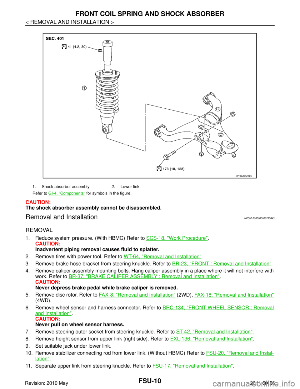
FRONT COIL SPRING AND SHOCK ABSORBER
CAUTION:
The shock absorber assembly cannot be disassembled.
Removal and InstallationINFOID:0000000006225643
REMOVAL
1. Reduce system pressure. (With HBMC) Refer to SCS-18, "Work Procedure".
CAUTION:
Inadvertent piping removal causes fluid to splatter.
2. Remove tires with power tool. Refer to WT-64, "
Removal and Installation".
3. Remove brake hose bracket from steering knuckle. Refer to BR-23, "
FRONT : Removal and Installation".
4. Remove caliper assembly mounting bolts. Hang caliper assembly in a place where it will not interfere with work. Refer to BR-37, "
BRAKE CALIPER ASSEMBLY : Removal and Installation".
CAUTION:
Never depress brake pedal while brake caliper is removed.
5. Remove disc rotor. Refer to FA X - 8 , "
Removal and Installation" (2WD), FAX-18, "Removal and Installation"
(4WD).
6. Remove wheel sensor and harness connector. Refer to BRC-134, "
FRONT WHEEL SENSOR : Removal
and Installation".
CAUTION:
Never pull on wheel sensor harness.
7. Remove steering outer socket fr om steering knuckle. Refer to ST-42, "
Removal and Installation".
8. Remove height sensor from upper link (right side). Refer to EXL-136, "
Removal and Installation".
9. Set suitable jack under lower link.
10. Remove stabilizer connecting rod from lower link. (Without HBMC) Refer to FSU-20, "
Removal and Instal-
lation".
11. Separate upper link from steering knuckle. Refer to FSU-17, "
Removal and Installation".
1. Shock absorber assembly 2. Lower link
Refer to GI-4, "
Components" for symbols in the figure.
JPEIA0256GB
Revision: 2010 May2011 QX56
Page 2956 of 5598

FSU-14
< REMOVAL AND INSTALLATION >
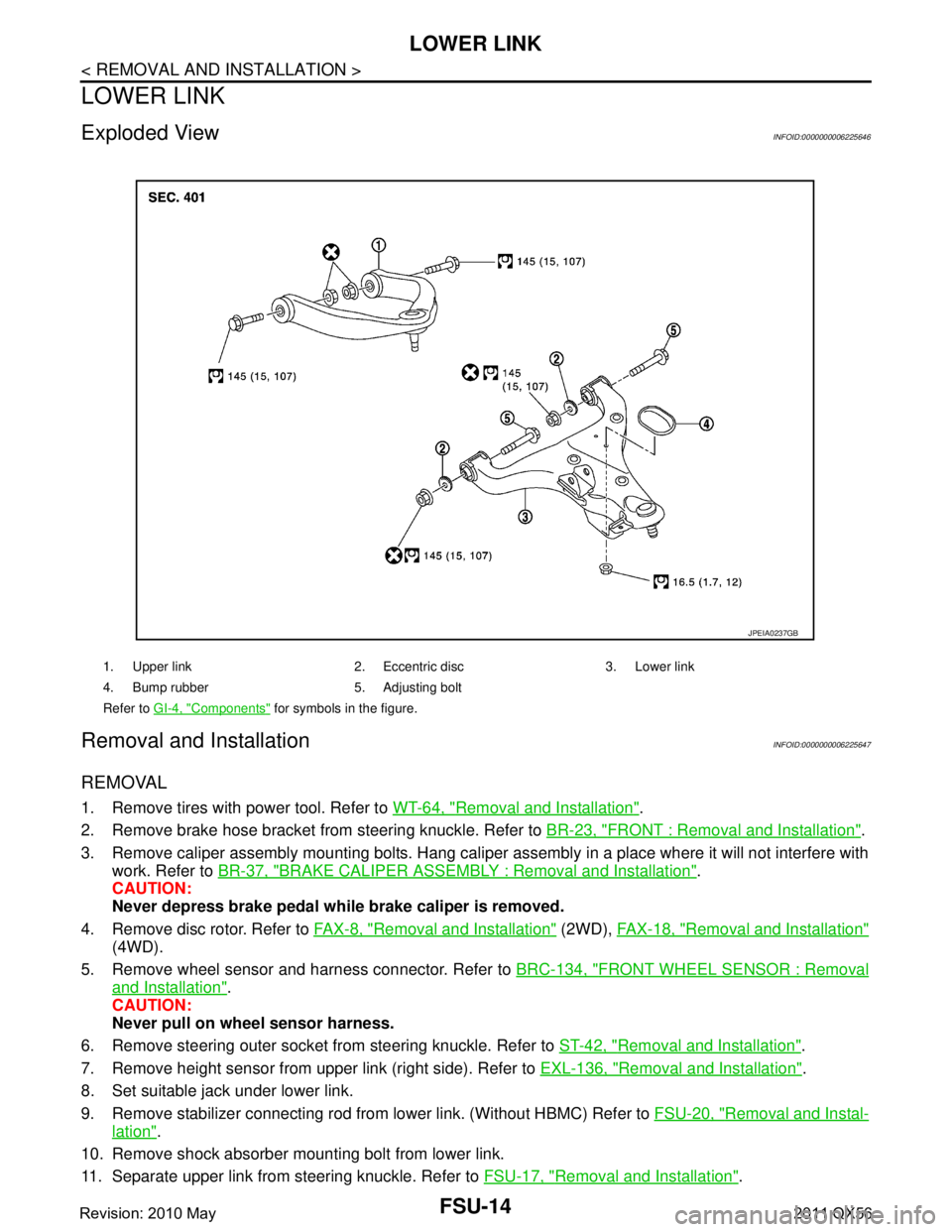
LOWER LINK
LOWER LINK
Exploded ViewINFOID:0000000006225646
Removal and InstallationINFOID:0000000006225647
REMOVAL
1. Remove tires with power tool. Refer to WT-64, "Removal and Installation".
2. Remove brake hose bracket from steering knuckle. Refer to BR-23, "
FRONT : Removal and Installation".
3. Remove caliper assembly mounting bolts. Hang caliper assembly in a place where it will not interfere with work. Refer to BR-37, "
BRAKE CALIPER ASSEMBLY : Removal and Installation".
CAUTION:
Never depress brake pedal while brake caliper is removed.
4. Remove disc rotor. Refer to FA X - 8 , "
Removal and Installation" (2WD), FAX-18, "Removal and Installation"
(4WD).
5. Remove wheel sensor and harness connector. Refer to BRC-134, "
FRONT WHEEL SENSOR : Removal
and Installation".
CAUTION:
Never pull on wheel sensor harness.
6. Remove steering outer socket fr om steering knuckle. Refer to ST-42, "
Removal and Installation".
7. Remove height sensor from upper link (right side). Refer to EXL-136, "
Removal and Installation".
8. Set suitable jack under lower link.
9. Remove stabilizer connecting rod from lower link. (Without HBMC) Refer to FSU-20, "
Removal and Instal-
lation".
10. Remove shock absorber mounting bolt from lower link.
11. Separate upper link from steering knuckle. Refer to FSU-17, "
Removal and Installation".
1. Upper link 2. Eccentric disc 3. Lower link
4. Bump rubber 5. Adjusting bolt
Refer to GI-4, "
Components" for symbols in the figure.
JPEIA0237GB
Revision: 2010 May2011 QX56
Page 2959 of 5598

UPPER LINKFSU-17
< REMOVAL AND INSTALLATION >
C
DF
G H
I
J
K L
M A
B
FSU
N
O P
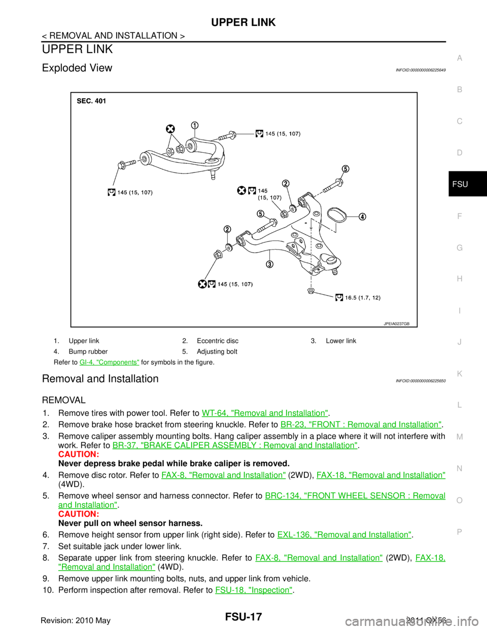
UPPER LINK
Exploded ViewINFOID:0000000006225649
Removal and InstallationINFOID:0000000006225650
REMOVAL
1. Remove tires with power tool. Refer to WT-64, "Removal and Installation".
2. Remove brake hose bracket from steering knuckle. Refer to BR-23, "
FRONT : Removal and Installation".
3. Remove caliper assembly mounting bolts. Hang caliper assembly in a place where it will not interfere with work. Refer to BR-37, "
BRAKE CALIPER ASSEMBLY : Removal and Installation".
CAUTION:
Never depress brake pedal while brake caliper is removed.
4. Remove disc rotor. Refer to FA X - 8 , "
Removal and Installation" (2WD), FAX-18, "Removal and Installation"
(4WD).
5. Remove wheel sensor and harness connector. Refer to BRC-134, "
FRONT WHEEL SENSOR : Removal
and Installation".
CAUTION:
Never pull on wheel sensor harness.
6. Remove height sensor from upper link (right side). Refer to EXL-136, "
Removal and Installation".
7. Set suitable jack under lower link.
8. Separate upper link from steering knuckle. Refer to FA X - 8 , "
Removal and Installation" (2WD), FAX-18,
"Removal and Installation" (4WD).
9. Remove upper link mounting bolts, nuts, and upper link from vehicle.
10. Perform inspection after removal. Refer to FSU-18, "
Inspection".
1. Upper link 2. Eccentric disc 3. Lower link
4. Bump rubber 5. Adjusting bolt
Refer to GI-4, "
Components" for symbols in the figure.
JPEIA0237GB
Revision: 2010 May2011 QX56