Page 438 of 5598
BCS-50
< ECU DIAGNOSIS INFORMATION >
BCM
81
(Y/R) Ground
Passenger door an-
tenna (-) OutputWhen the pas-
senger door re-
quest switch is
operated with
ignition switch
OFF When Intelligent Key is
not in the antenna detec-
tion area
When Intelligent Key is in
the antenna detection
area
82
(W/G) Ground Back door antenna
(+)
OutputWhen the back
door request
switch is operat-
ed with ignition
switch OFF When Intelligent Key is
not in the antenna detec-
tion area
When Intelligent Key is in
the antenna detection
area
83
(B/W) Ground Back door antenna (-
) OutputWhen the back
door request
switch is operat-
ed with ignition
switch OFF When Intelligent Key is
not in the antenna detec-
tion area
When Intelligent Key is in
the antenna detection
area
Te r m i n a l N o .
(Wire color) Description
Condition Va l u e
(Approx.)
Signal name Input/
Output
+ −
JMKIA3838GB
JMKIA3839GB
JMKIA3838GB
JMKIA3839GB
JMKIA3838GB
JMKIA3839GB
Revision: 2010 May2011 QX56
Page 677 of 5598

BRM-2
< VEHICLE INFORMATION >
BODY EXTERIOR PAINT COLOR
VEHICLE INFORMATION
BODY EXTERIOR PAINT COLOR
Body Exterior Paint ColorINFOID:0000000006248483
NOTE:
•S: Solid
2S: Solid + Clear
CS: Color clear solid
M: Metallic
P: 2-Coat pearl
3P: 3-Coat pearl
FPM: Iron oxide pearl Component
Color code BQAA BK23 BKH3 BK51 BL50 BJAE
Description White Silver Black Gray
Brownish
Purple Grayish
Green
Paint type
note3P M 2S M P M
Hard clear
coat ××××××
1 Front grille Chromium
plateCr Cr Cr Cr Cr Cr
2 Front bumper fascia Body color BQAA BK23 BKH3 BK51 BL50 BJAE
3 Over fender Body color B QAA BK23 BKH3 BK51 BL50 BJAE
4 Front fender duct Chromium
plate
Cr Cr Cr Cr Cr Cr
5 Door
outside
mirror
Cover Body color BQAA BK23 BKH3 BK51 BL50 BJAE
6 Front pillar finisher Black G01 G01 G01 G01 G01 G01
7 Back door air spoiler Body color BQAA BK23 BKH3 BK51 BL50 BJAE
8 Door outside handle Chromium
plate
Cr Cr Cr Cr Cr Cr
9 Side step Body color BQAA BK23 BKH3 BK51 BL50 BJAE
10 Rear bumper fascia Body color BQAA BK23 BKH3 BK51 BL50 BJAE
11 Back door finisher Chromium
plateCr Cr Cr Cr Cr Cr
JSKIA1965ZZ
Revision: 2010 May2011 QX56
Page 687 of 5598

BRM-12
< PREPARATION >
BODY COMPONENT PARTS
NOTE:
For the parts without a number described in the figure, it is supplied only with the assembly part that the part is included with.
Tensile strength column shows the largest strength value of a part in the component part. No. Parts name
Tensile strength
(MPa) Both sided anti-corrosive
precoated steel sections
1. Hood Under 440×
2. Front fender (RH & LH) Under 440 ×
3. Inner side roof rail (RH & LH) 590 —
4. Upper inner front pillar (RH & LH) c. T=1.6 mm
(0.063 in)
980
caution—
5. Inner center pillar (RH & LH) d. T=1.6 mm
(0.063 in)
980
caution×
6. Center sill reinforcement assembly (RH & LH) Under 440 ×
7. Side body assembly (RH & LH) Refer to No.8 −13
8. Upper front pillar reinforcement (RH & LH) 590 —
9. Lower center pillar brace (RH & LH) e. T=1.8 mm
(0.071 in)
980
caution—
10. Front pillar brace (RH & LH) 590 —
11. Outer sill reinforcement (RH & LH) 590 ×
12. Outer front side body (RH & LH) Under 440 ×
13. Front fender bracket assembly (RH & LH) Under 440 ×
14. Outer sill (RH & LH) Under 440 ×
15. Front door assembly (RH & LH) 440 ×
16. Outer front door panel (RH & LH) Under 440 ×
17. Rear door assembly (RH & LH) 440 ×
18. Outer rear door panel (RH & LH) Under 440 ×
19. Back pillar reinforcement (RH & LH) Under 440 —
20. Inner back pillar (RH & LH) Under 440 —
21. Inner rear side roof rail (RH & LH) Under 440 —
22. Inner rear pillar (RH & LH) 590 —
23. Lower inner rear pillar (RH & LH)v Under 440 —
24. Side panel reinforcement (RH & LH) Under 440 —
25. Outer rear wheelhouse (RH & LH) Under 440 ×
26. Inner rear wheelhouse (RH & LH) Under 440 ×
27. Outer rear wheelhouse extension (RH & LH) Under 440 ×
28. Roof assembly Under 440 —
29. Front roof rail 440 —
30. Roof bow No.3 Under 440 —
31. Roof bow No.4 Under 440 —
32. Roof bow No.5 Under 440 —
33. Rear roof rail 440 —
34. Rear fender (RH & LH) Under 440 ×
35. Back pillar assembly (RH & LH) Under 440 —
36. Rear fender bracket (RH & LH) Under 440 —
37. Fuel filler lid Under 440 ×
38. Rear fender extension (RH & LH) Under 440 ×
39. Back door Under 440 ×
Revision: 2010 May2011 QX56
Page 734 of 5598

LOCATION OF PLASTIC PARTSBRM-59
< SERVICE DATA AND SPECIFICATIONS (SDS)
C
DE
F
G H
I
J
L
M A
B
BRM
N
O P
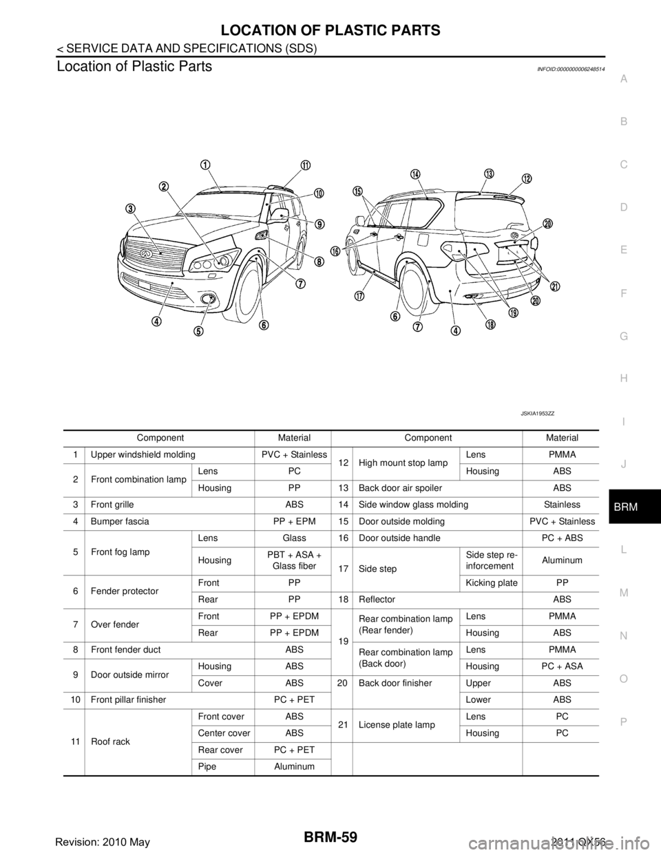
Location of Plastic PartsINFOID:0000000006248514
Component Material Component Material
1 Upper windshield molding PVC + Stainless 12 High mount stop lampLens PMMA
2 Front combination lamp Lens PC Housing ABS
Housing PP 13 Back door air spoiler ABS
3 Front grille ABS 14 Side window glass molding Stainless
4 Bumper fascia PP + EPM 15 Door outside molding PVC + Stainless
5 Front fog lamp Lens Glass 16 Door outside handle PC + ABS
Housing
PBT + ASA +
Glass fiber 17 Side step Side step re-
inforcement
Aluminum
6 Fender protector Front PP Kicking plate PP
Rear PP 18 Reflector ABS
7 Over fender Front PP + EPDM
19Rear combination lamp
(Rear fender)
Lens PMMA
Rear PP + EPDM Housing ABS
8 Front fender duct ABS Rear combination lamp
(Back door)Lens PMMA
9 Door outside mirror Housing ABS Housing PC + ASA
Cover ABS 20 Back door finisher Upper ABS
10 Front pillar finisher PC + PET Lower ABS
11 R o o f r a c k Front cover ABS
21 License plate lampLens PC
Center cover ABS Housing PC
Rear cover PC + PET
Pipe Aluminum
JSKIA1953ZZ
Revision: 2010 May2011 QX56
Page 1236 of 5598
DAS
WARNING SYSTEMS SWITCHDAS-271
< REMOVAL AND INSTALLATION > [FCW]
C
D
E
F
G H
I
J
K L
M B
N P A
REMOVAL AND INSTALLATION
WARNING SYSTEMS SWITCH
Removal and InstallationINFOID:0000000006223696
REMOVAL
1. Remove the instrument lower panel (LH). Refer to IP-14, "Removal and Installation".
2. Remove warning systems switch from instrument driver lower panel.
NOTE:
Warning systems switch and automatic back door switch are integrated.
INSTALLATION
Install in the reverse order of removal.
Revision: 2010 May2011 QX56
Page 1369 of 5598
DAS-404
< REMOVAL AND INSTALLATION >[LDW & LDP]
WARNING SYSTEMS SWITCH
WARNING SYSTEMS SWITCH
Removal and InstallationINFOID:0000000006223844
REMOVAL
1. Remove the instrument lower panel (LH). Refer to
IP-14, "Removal and Installation".
2. Remove warning systems switch from instrument driver lower panel.
NOTE:
Warning systems switch and automatic back door switch are integrated.
INSTALLATION
Install in the reverse order of removal.
Revision: 2010 May2011 QX56
Page 1492 of 5598
DAS
WARNING SYSTEMS SWITCHDAS-527
< REMOVAL AND INSTALLATION > [BSW]
C
D
E
F
G H
I
J
K L
M B
N P A
WARNING SYSTEMS SWITCH
Removal and InstallationINFOID:0000000006223984
REMOVAL
1. Remove the instrument lower panel (LH). Refer to IP-14, "Removal and Installation".
2. Remove warning systems switch from instrument driver lower panel.
NOTE:
Warning systems switch and automatic back door switch are integrated.
INSTALLATION
Install in the reverse order of removal.
Revision: 2010 May2011 QX56
Page 1499 of 5598

DIAGNOSIS SYSTEM (BCM)DEF-7
< SYSTEM DESCRIPTION >
C
DE
F
G H
I
J
K
M A
B
DEF
N
O P
DIAGNOSIS SYSTEM (BCM)
COMMON ITEM
COMMON ITEM : CONSULT-III Fu nction (BCM - COMMON ITEM)INFOID:0000000006349773
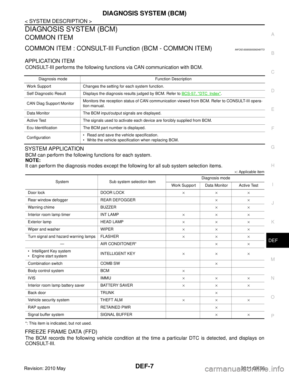
APPLICATION ITEM
CONSULT-III performs the following functions via CAN communication with BCM.
SYSTEM APPLICATION
BCM can perform the following functions for each system.
NOTE:
It can perform the diagnosis modes except the following for all sub system selection items.
×: Applicable item
*: This item is indicated, but not used.
FREEZE FRAME DATA (FFD)
The BCM records the following vehicle condition at the time a particular DTC is detected, and displays on
CONSULT-III.
Diagnosis mode Function Description
Work Support Changes the setting for each system function.
Self Diagnostic Result Displays the diagnosis results judged by BCM. Refer to BCS-57, "
DTCIndex".
CAN Diag Support Monitor Monitors the reception status of CAN communication viewed from BCM. Refer to CONSULT-III opera-
tion manual.
Data Monitor The BCM input/output signals are displayed.
Active Test The signals used to activate each device are forcibly supplied from BCM.
Ecu Identification The BCM part number is displayed.
Configuration Read and save the vehicle specification.
Write the vehicle specification when replacing BCM.
System Sub system selection item Diagnosis mode
Work Support Data Monitor Active Test
Door lock DOOR LOCK ×××
Rear window defo gger REAR DEFOGGER ××
Warning chime BUZZER ××
Interior room lamp timer INT LAMP ×××
Exterior lamp HEAD LAMP ×××
Wiper and washer WIPER ×××
Turn signal and hazard warning lamps FLASHER ×××
— AIR CONDITONER* ××
Intelligent Key system
Engine start system INTELLIGENT KEY
×××
Combination switch COMB SW ×
Body control system BCM ×
IVIS IMMU ×××
Interior room lamp battery saver BATTERY SAVER ×××
Back door TRUNK ×
Vehicle security system THEFT ALM ×××
RAP system RETAINED PWR ×
Signal buffer system SIGNAL BUFFER ××
Revision: 2010 May2011 QX56