Page 2908 of 5598
![INFINITI QX56 2011 Factory Service Manual
FAX-8
< REMOVAL AND INSTALLATION >[2WD]
FRONT WHEEL HUB AND KNUCKLE
REMOVAL AND INSTALLATION
FRONT WHEEL HUB AND KNUCKLE
Exploded ViewINFOID:0000000006225418
Removal and InstallationINFOID:0000000006 INFINITI QX56 2011 Factory Service Manual
FAX-8
< REMOVAL AND INSTALLATION >[2WD]
FRONT WHEEL HUB AND KNUCKLE
REMOVAL AND INSTALLATION
FRONT WHEEL HUB AND KNUCKLE
Exploded ViewINFOID:0000000006225418
Removal and InstallationINFOID:0000000006](/manual-img/42/57033/w960_57033-2907.png)
FAX-8
< REMOVAL AND INSTALLATION >[2WD]
FRONT WHEEL HUB AND KNUCKLE
REMOVAL AND INSTALLATION
FRONT WHEEL HUB AND KNUCKLE
Exploded ViewINFOID:0000000006225418
Removal and InstallationINFOID:0000000006225419
REMOVAL
1. Remove tires with power tool. Refer to
WT-64, "Removal and Installation".
2. Remove brake hose bracket. Refer to BR-23, "
FRONT : Removal and Installation".
3. Remove caliper assembly mounting bolts. Hang caliper assembly in a place where it will not interfere with work. Refer to BR-37, "
BRAKE CALIPER ASSEMBLY : Removal and Installation".
CAUTION:
Never depress brake pedal while brake caliper is removed.
4. Remove disc rotor. CAUTION:
Put matching marks on the wh eel hub and bearing assembly and the disc rotor before removing
the disc rotor.
Never drop disc rotor.
5. Remove wheel sensor harness. Refer to BRC-134, "
FRONT WHEEL SENSOR : Removal and Installa-
tion".
CAUTION:
Never pull on wheel sensor harness.
6. Remove steering outer socket. Refer to ST-42, "
Removal and Installation".
7. Set suitable jack under lower link.
1. Steering knuckle 2. Cotter pin 3. Splash guard
4. Hub bolt 5. Wheel hub and bearing assembly 6. Disc rotor
Refer to GI-4, "
Components" for symbols in the figure.
JPDIF0294GB
Revision: 2010 May2011 QX56
Page 2912 of 5598
![INFINITI QX56 2011 Factory Service Manual
FAX-12
< PRECAUTION >[4WD]
PRECAUTIONS
5. When the repair work is completed, re-connect bot
h battery cables. With the brake pedal released, turn
the push-button ignition switch from ACC position to INFINITI QX56 2011 Factory Service Manual
FAX-12
< PRECAUTION >[4WD]
PRECAUTIONS
5. When the repair work is completed, re-connect bot
h battery cables. With the brake pedal released, turn
the push-button ignition switch from ACC position to](/manual-img/42/57033/w960_57033-2911.png)
FAX-12
< PRECAUTION >[4WD]
PRECAUTIONS
5. When the repair work is completed, re-connect bot
h battery cables. With the brake pedal released, turn
the push-button ignition switch from ACC position to ON position, then to LOCK position. (The steering
wheel will lock when the push-button igniti on switch is turned to LOCK position.)
6. Perform self-diagnosis check of all control units using CONSULT-III.
Precautions for Drive ShaftINFOID:0000000006225390
Observe the following precautions when disassembling and assembling drive shaft.
- Never disassemble joint sub-assembly because it is non-overhaul parts.
- Perform work in a location which is as dust-free as possible.
- Clean the parts, before disassembling and assembling.
- Prevent the entry of foreign objects dur ing disassembly of the service location.
- Reassemble disassembled parts carefully in the correct order. If work is interrupted, a clean cover must be placed over parts.
- Use paper waste. Fabric shop cloths must not be used because of the danger of lint adhering to parts.
- Clean disassembled parts (except for rubber parts) with kerosene which shall be removed by blowing with
air or wiping with paper waste.
Revision: 2010 May2011 QX56
Page 2915 of 5598
![INFINITI QX56 2011 Factory Service Manual
NOISE, VIBRATION AND HARSHNESS (NVH) TROUBLESHOOTINGFAX-15
< SYMPTOM DIAGNOSIS > [4WD]
C
EF
G H
I
J
K L
M A
B
FA X
N
O P
SYMPTOM DIAGNOSIS
NOISE, VIBRATION AND HARSHN ESS (NVH) TROUBLESHOOTING
NVH Tr INFINITI QX56 2011 Factory Service Manual
NOISE, VIBRATION AND HARSHNESS (NVH) TROUBLESHOOTINGFAX-15
< SYMPTOM DIAGNOSIS > [4WD]
C
EF
G H
I
J
K L
M A
B
FA X
N
O P
SYMPTOM DIAGNOSIS
NOISE, VIBRATION AND HARSHN ESS (NVH) TROUBLESHOOTING
NVH Tr](/manual-img/42/57033/w960_57033-2914.png)
NOISE, VIBRATION AND HARSHNESS (NVH) TROUBLESHOOTINGFAX-15
< SYMPTOM DIAGNOSIS > [4WD]
C
EF
G H
I
J
K L
M A
B
FA X
N
O P
SYMPTOM DIAGNOSIS
NOISE, VIBRATION AND HARSHN ESS (NVH) TROUBLESHOOTING
NVH Troubleshooting ChartINFOID:0000000006225393
Use chart below to find the cause of the symptom. If necessary, repair or replace these parts.
×: ApplicableReference
—
FAX-28—
FAX-18—
FAX-16
NVH in FAX and FSU sections
Refer to FRONT AXLE in this chart.
NVH in WT section
NVH in WT section
Refer to DRIVE SHAFT in this chart.
NVH in BR section
NVH in ST section
Possible cause and SUSPECTED PARTS
Excessive joint angle
Joint sliding resistance
Imbalance
Improper installation, looseness
Parts interference
Wheel bearing damage
FRONT AXLE AND FRONT SUSPENSION
FRONT AXLE
TIRE
ROAD WHEEL
DRIVE SHAFT
BRAKE
STEERING
Symptom DRIVE
SHAFT
Noise
×× ××××× ××
Shake × × ××××× ××
FRONT
AXLE Noise
×××× ×××××
Shake ×××× ×××××
Vibration ×××× × × ×
Shimmy ×× × ×× ××
Judder × × ×× ××
Poor quality ride or handling ×× × ××
Revision: 2010 May2011 QX56
Page 2918 of 5598
![INFINITI QX56 2011 Factory Service Manual
FAX-18
< REMOVAL AND INSTALLATION >[4WD]
FRONT WHEEL HUB AND KNUCKLE
REMOVAL AND INSTALLATION
FRONT WHEEL HUB AND KNUCKLE
Exploded ViewINFOID:0000000006225396
Removal and InstallationINFOID:000000000 INFINITI QX56 2011 Factory Service Manual
FAX-18
< REMOVAL AND INSTALLATION >[4WD]
FRONT WHEEL HUB AND KNUCKLE
REMOVAL AND INSTALLATION
FRONT WHEEL HUB AND KNUCKLE
Exploded ViewINFOID:0000000006225396
Removal and InstallationINFOID:000000000](/manual-img/42/57033/w960_57033-2917.png)
FAX-18
< REMOVAL AND INSTALLATION >[4WD]
FRONT WHEEL HUB AND KNUCKLE
REMOVAL AND INSTALLATION
FRONT WHEEL HUB AND KNUCKLE
Exploded ViewINFOID:0000000006225396
Removal and InstallationINFOID:0000000006225397
REMOVAL
1. Remove tires.
2. Remove brake hose bracket. Refer to
BR-23, "
FRONT : Removal and Installation".
3. Remove caliper assembly mounting bolts. Hang caliper assembly in a place where it will not interfere with work. Refer to BR-37, "
BRAKE CALIPER ASSEMBLY : Removal and Installation".
CAUTION:
Never depress brake pedal while brake caliper is removed.
4. Remove disc rotor. CAUTION:
Put matching marks on the wh eel hub and bearing assembly and the disc rotor before removing
the disc rotor.
Never drop disc rotor.
5. Remove wheel sensor harness. Refer to BRC-134, "
FRONT WHEEL SENSOR : Removal and Installa-
tion".
CAUTION:
Never pull on wheel sensor harness.
6. Remove steering outer socket. Refer to ST-42, "
Removal and Installation".
1. Steering knuckle 2. Cotter pin 3. Splash guard
4. Hub bolt 5. Wheel hub and bearing assembly 6. Disc rotor
7. Wheel hub lock nut
A. Tightening must be done following the installation procedure. Refer to FA X - 1 8 , "
Removal and Installation".
Refer to GI-4, "
Components" for symbols in the figure.
JPDIF0298GB
Revision: 2010 May2011 QX56
Page 2922 of 5598
![INFINITI QX56 2011 Factory Service Manual
FAX-22
< REMOVAL AND INSTALLATION >[4WD]
FRONT DRIVE SHAFT
FRONT DRIVE SHAFT
Exploded ViewINFOID:0000000006225402
Removal and InstallationINFOID:0000000006225403
REMOVAL
1. Remove tires.
2. Remove br INFINITI QX56 2011 Factory Service Manual
FAX-22
< REMOVAL AND INSTALLATION >[4WD]
FRONT DRIVE SHAFT
FRONT DRIVE SHAFT
Exploded ViewINFOID:0000000006225402
Removal and InstallationINFOID:0000000006225403
REMOVAL
1. Remove tires.
2. Remove br](/manual-img/42/57033/w960_57033-2921.png)
FAX-22
< REMOVAL AND INSTALLATION >[4WD]
FRONT DRIVE SHAFT
FRONT DRIVE SHAFT
Exploded ViewINFOID:0000000006225402
Removal and InstallationINFOID:0000000006225403
REMOVAL
1. Remove tires.
2. Remove brake hose bracket. Refer to
BR-23, "
FRONT : Removal and Installation".
3. Remove caliper assembly mounting bolts. Hang caliper assembly in a place where it will not interfere with work. Refer to BR-37, "
BRAKE CALIPER ASSEMBLY : Removal and Installation".
CAUTION:
Never depress brake pedal while brake caliper is removed.
4. Remove disc rotor. Refer to FAX-18, "
Removal and Installation".
5. Remove wheel sensor harness. Refer to BRC-134, "
FRONT WHEEL SENSOR : Removal and Installa-
tion".
CAUTION:
Never pull on wheel sensor harness.
6. Remove height sensor from upper link (right side). Refer to EXL-136, "
Removal and Installation".
7. Remove steering outer socket. Refer to ST-42, "
Removal and Installation".
8. Set suitable jack under lower link.
9. Remove shock absorber mounting bolt from lower link. Refer to FSU-10, "
Removal and Installation".
10. Separate upper link from steering knuckle, using t he ball joint remover (commercial service tool), and
remove upper link.
CAUTION:
Temporarily tighten the nut to prevent damage to threads and to prevent the ball joint remover
from suddenly coming off.
1. Circular clip 2. Dust shield 3. Housing
4. Snap ring 5. Ball cage/steel ball/inner race assem-
bly6. Stopper ring
7. Boot band 8. Boot 9. Shaft
10. Circular clip 11. Joint sub-assembly : Wheel side
: NISSAN genuine grease or an equivalent.
Refer to GI-4, "
Components" for symbols not described on the above.
JPDIF0279ZZ
Revision: 2010 May2011 QX56
Page 2945 of 5598

PRECAUTIONSFSU-3
< PRECAUTION >
C
DF
G H
I
J
K L
M A
B
FSU
N
O P
5. When the repair work is completed, re-connect both battery cables. With the brake pedal released, turn
the push-button ignition switch from ACC position to ON position, then to LOCK position. (The steering
wheel will lock when the push-button ignition switch is turned to LOCK position.)
6. Perform self-diagnosis check of a ll control units using CONSULT-III.
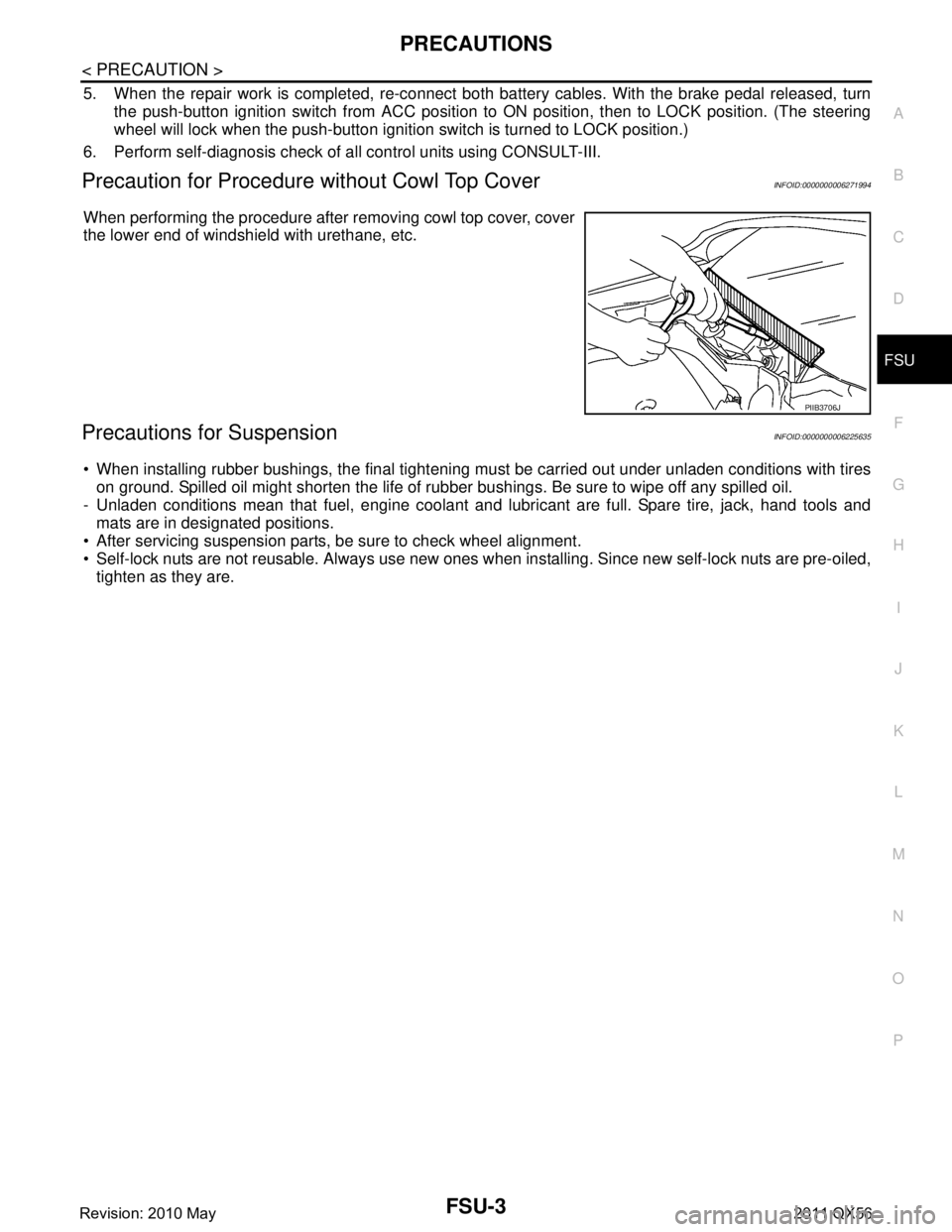
Precaution for Procedure without Cowl Top CoverINFOID:0000000006271994
When performing the procedure after removing cowl top cover, cover
the lower end of windshield with urethane, etc.
Precautions for SuspensionINFOID:0000000006225635
When installing rubber bushings, the final tightening mu st be carried out under unladen conditions with tires
on ground. Spilled oil might shorten the life of rubb er bushings. Be sure to wipe off any spilled oil.
- Unladen conditions mean that fuel, engine coolant and l ubricant are full. Spare tire, jack, hand tools and
mats are in designated positions.
After servicing suspension parts, be sure to check wheel alignment.
Self-lock nuts are not reusable. Always use new ones w hen installing. Since new self-lock nuts are pre-oiled,
tighten as they are.
PIIB3706J
Revision: 2010 May2011 QX56
Page 2947 of 5598

NOISE, VIBRATION AND HARSHNESS (NVH) TROUBLESHOOTINGFSU-5
< SYMPTOM DIAGNOSIS >
C
DF
G H
I
J
K L
M A
B
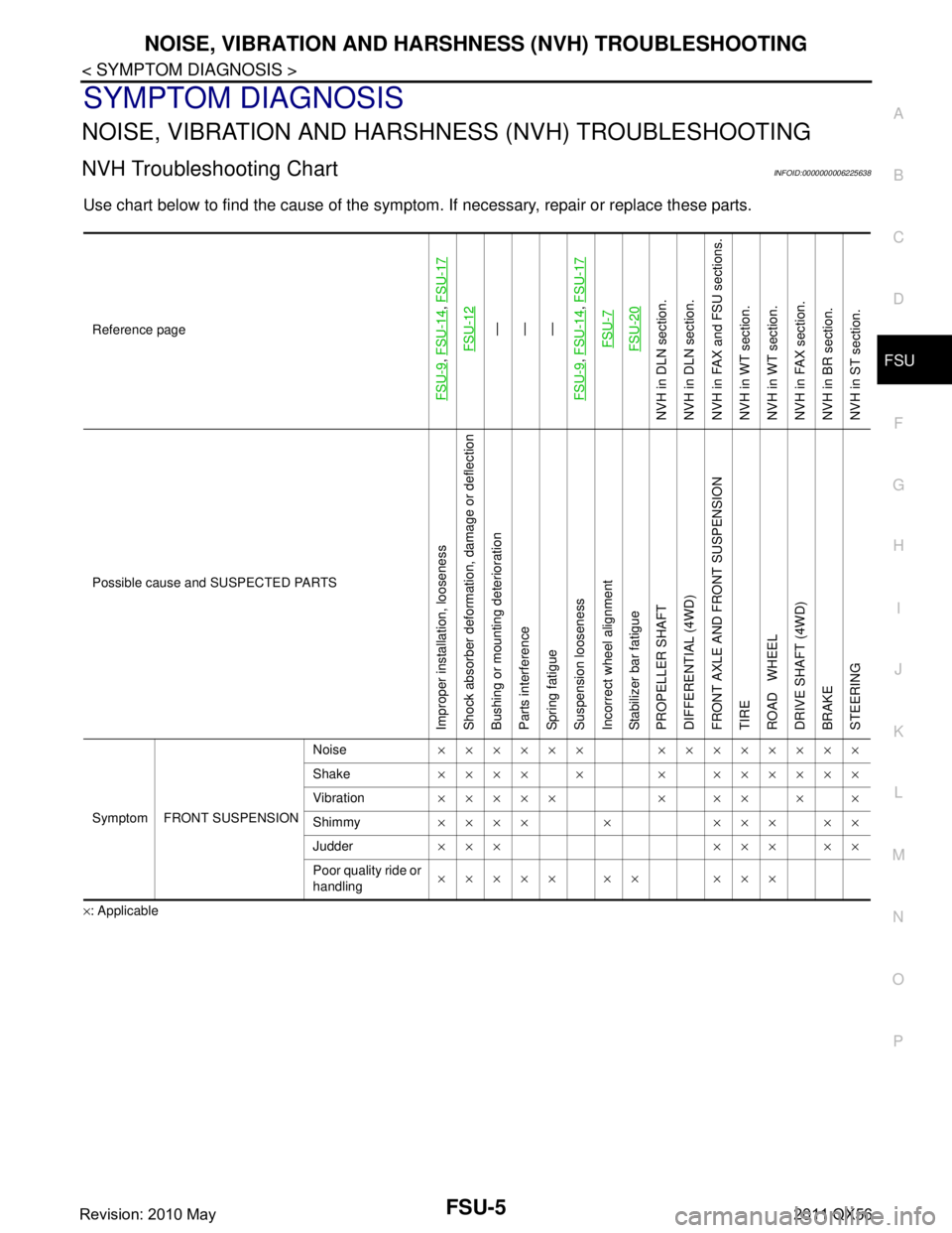
FSU
N
O P
SYMPTOM DIAGNOSIS
NOISE, VIBRATION AND HARSHN ESS (NVH) TROUBLESHOOTING
NVH Troubleshooting ChartINFOID:0000000006225638
Use chart below to find the cause of the symptom. If necessary, repair or replace these parts.
×: ApplicableReference page
FSU-9
,
FSU-14
, FSU-17
FSU-12
—
—
—
FSU-9
, FSU-14
, FSU-17
FSU-7FSU-20
NVH in DLN section.
NVH in DLN section.
NVH in FAX and FSU sections.
NVH in WT section.
NVH in WT section.
NVH in FAX section.
NVH in BR section.
NVH in ST section.
Possible cause and SUSPECTED PARTS
Improper installation, looseness
Shock absorber deformation, damage or deflection
Bushing or mounting deterioration
Parts interference
Spring fatigue
Suspension looseness
Incorrect wheel alignment
Stabilizer bar fatigue
PROPELLER SHAFT
DIFFERENTIAL (4WD)
FRONT AXLE AND FRONT SUSPENSION
TIRE
ROAD WHEEL
DRIVE SHAFT (4WD)
BRAKE
STEERING
Symptom FRONT SUSPENSION Noise
×××××× ××××××××
Shake ×××× × × ××××××
Vibration ××××× × ×× × ×
Shimmy ×××× × ××× ××
Judder ××× ××× ××
Poor quality ride or
handling ××××× ×× ×××
Revision: 2010 May2011 QX56
Page 2948 of 5598
FSU-6
< PERIODIC MAINTENANCE >
FRONT SUSPENSION ASSEMBLY
PERIODIC MAINTENANCE
FRONT SUSPENSION ASSEMBLY
InspectionINFOID:0000000006225639
MOUNTING INSPECTION
Check the mounting conditions (looseness, backlash) of each component and component conditions (wear,
damage) are normal.
BALL JOINT AXIAL END PLAY
1. Set front wheels in a straight-ahead position.
2. Measure axial end play by playing and moving up/dow n with iron bar or equivalent between lower link or
upper link and steering knuckle.
CAUTION:
Never depress brake pedal when measuring.
Never perform with tires on level ground.
Be careful not to damage ball joint boot. Never damage the installation position by applying
excessive force.
Shock absorber
Check for oil leakage, damage. Replace it if necessary. Axial end play : Refer to
FSU-21, "
Ball Joint".
Revision: 2010 May2011 QX56