2011 INFINITI QX56 Fuel
[x] Cancel search: FuelPage 3813 of 5598
MWI-70
< DTC/CIRCUIT DIAGNOSIS >
FUEL LEVEL SENSOR SIGNAL CIRCUIT
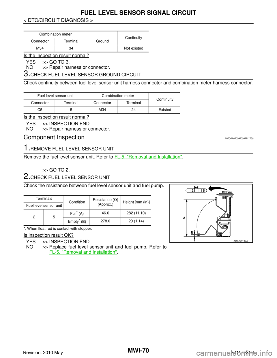
Is the inspection result normal?
YES >> GO TO 3.
NO >> Repair harness or connector.
3.CHECK FUEL LEVEL SENSOR GROUND CIRCUIT
Check continuity between fuel level sensor unit harness connector and combination meter harness connector.
Is the inspection result normal?
YES >> INSPECTION END
NO >> Repair harness or connector.
Component InspectionINFOID:0000000006221750
1.REMOVE FUEL LEVEL SENSOR UNIT
Remove the fuel level sensor unit. Refer to FL-5, "
Removal and Installation".
>> GO TO 2.
2.CHECK FUEL LEVEL SENSOR UNIT
Check the resistance between fuel level sensor unit and fuel pump.
*: When float rod is contact with stopper.
Is inspection result OK?
YES >> INSPECTION END
NO >> Replace fuel level sensor unit and fuel pump. Refer to FL-5, "
Removal and Installation".
Combination meter
GroundContinuity
Connector Terminal
M34 34 Not existed
Fuel level sensor unit Combination meter Continuity
Connector Terminal Connector Terminal
C5 5 M34 24 Existed
Te r m i n a l s ConditionResistance (
Ω)
(Approx.) Height [mm (in)]
Fuel level sensor unit
25 Full
* (A)
46.0 282 (11.10)
Empty
* (B) 278.0 29 (1.14)
JSNIA3018ZZ
Revision: 2010 May2011 QX56
Page 3818 of 5598
MWI
THE FUEL GAUGE INDICATOR DOES NOT OPERATE
MWI-75
< SYMPTOM DIAGNOSIS >
C
D E
F
G H
I
J
K L
M B A
O P
SYMPTOM DIAGNOSIS
THE FUEL GAUGE INDICA TOR DOES NOT OPERATE
DescriptionINFOID:0000000006221757
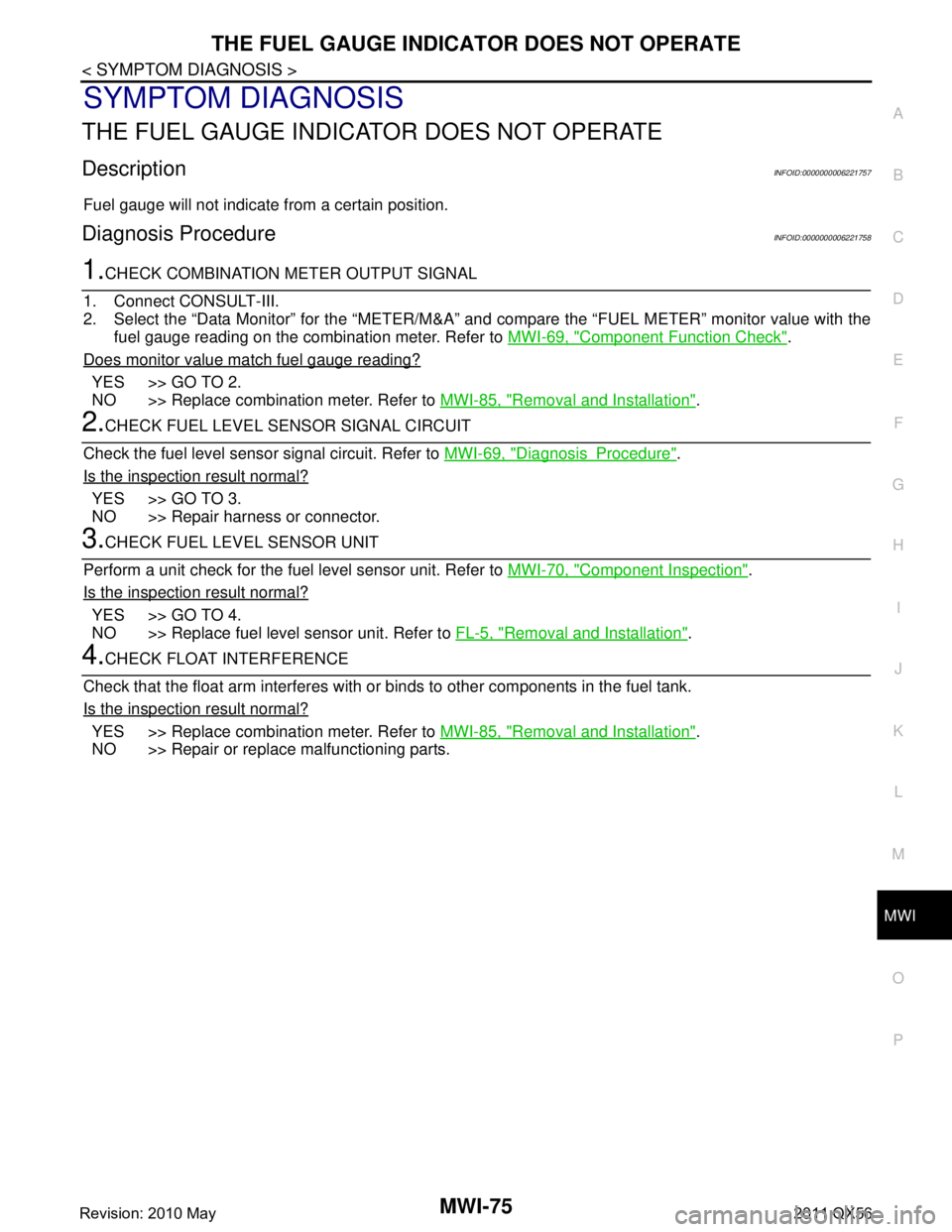
Fuel gauge will not indicate from a certain position.
Diagnosis ProcedureINFOID:0000000006221758
1.CHECK COMBINATION METER OUTPUT SIGNAL
1. Connect CONSULT-III.
2. Select the “Data Monitor” for the “METER/M&A” and compare the “FUEL METER” monitor value with the
fuel gauge reading on the combination meter. Refer to MWI-69, "
Component Function Check".
Does monitor value match fuel gauge reading?
YES >> GO TO 2.
NO >> Replace combination meter. Refer to MWI-85, "
Removal and Installation".
2.CHECK FUEL LEVEL SENSOR SIGNAL CIRCUIT
Check the fuel level sensor signal circuit. Refer to MWI-69, "
DiagnosisProcedure".
Is the inspection result normal?
YES >> GO TO 3.
NO >> Repair harness or connector.
3.CHECK FUEL LEVEL SENSOR UNIT
Perform a unit check for the fuel level sensor unit. Refer to MWI-70, "
Component Inspection".
Is the inspection result normal?
YES >> GO TO 4.
NO >> Replace fuel level sensor unit. Refer to FL-5, "
Removal and Installation".
4.CHECK FLOAT INTERFERENCE
Check that the float arm interferes with or binds to other components in the fuel tank.
Is the inspection result normal?
YES >> Replace combination meter. Refer to MWI-85, "Removal and Installation".
NO >> Repair or replace malfunctioning parts.
Revision: 2010 May2011 QX56
Page 3827 of 5598
MWI-84
< SYMPTOM DIAGNOSIS >
NORMAL OPERATING CONDITION
NORMAL OPERATING CONDITION
INFORMATION DISPLAY
INFORMATION DISPLAY : DescriptionINFOID:0000000006221775
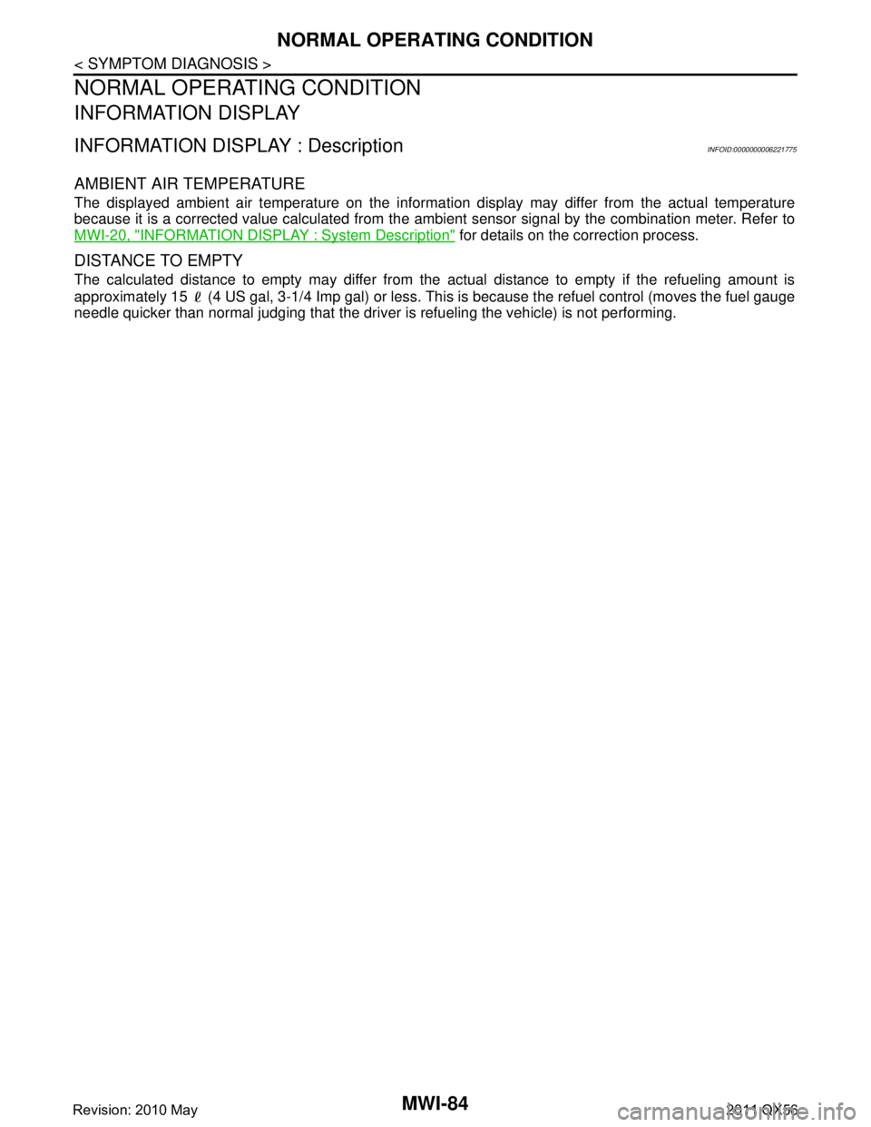
AMBIENT AIR TEMPERATURE
The displayed ambient air temperature on the information display may differ from the actual temperature
because it is a corrected value calculated from the ambi ent sensor signal by the combination meter. Refer to
MWI-20, "
INFORMATION DISPLAY : System Description" for details on the correction process.
DISTANCE TO EMPTY
The calculated distance to empty may differ from the actual distance to empty if the refueling amount is
approximately 15 (4 US gal, 3-1/4 Imp gal) or less. Th is is because the refuel control (moves the fuel gauge
needle quicker than normal judging that the driver is refueling the vehicle) is not performing.
Revision: 2010 May2011 QX56
Page 4257 of 5598

RSU-2
< PRECAUTION >
PRECAUTIONS
PRECAUTION
PRECAUTIONS
Precautions for SuspensionINFOID:0000000006225656
• When installing rubber bushings, the final tightening must be carried out under unladen conditions with tires
on ground. Spilled oil might shorten the life of rubber bushings. Be sure to wipe off any spilled oil.
- Unladen conditions mean that fuel, engine coolant and l ubricant are full. Spare tire, jack, hand tools and
mats are in designated positions.
After servicing suspension parts, be sure to check wheel alignment.
Self-lock nuts are not reusable. Always use new ones when installing. Since new self-lock nuts are pre-oiled,
tighten as they are.
Revision: 2010 May2011 QX56
Page 4261 of 5598
RSU-6
< PERIODIC MAINTENANCE >
WHEEL ALIGNMENT
WHEEL ALIGNMENT
InspectionINFOID:0000000006225661
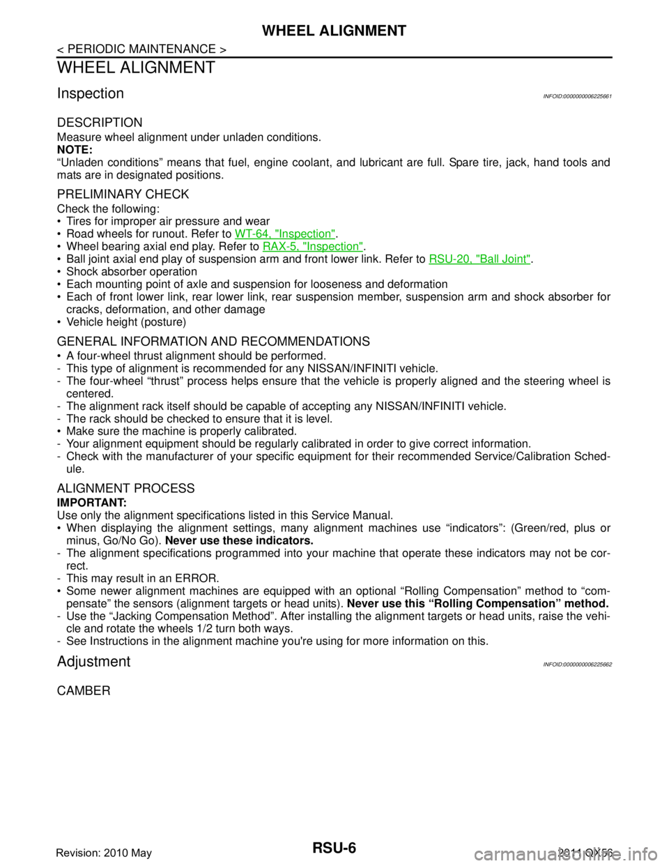
DESCRIPTION
Measure wheel alignment under unladen conditions.
NOTE:
“Unladen conditions” means that fuel, engine coolant, and lubricant are full. Spare tire, jack, hand tools and
mats are in designated positions.
PRELIMINARY CHECK
Check the following:
Tires for improper air pressure and wear
Road wheels for runout. Refer to WT-64, "
Inspection".
Wheel bearing axial end play. Refer to RAX-5, "
Inspection".
Ball joint axial end play of suspension arm and front lower link. Refer to RSU-20, "
Ball Joint".
Shock absorber operation
Each mounting point of axle and suspension for looseness and deformation
Each of front lower link, rear lower link, rear suspension member, suspension arm and shock absorber for
cracks, deformation, and other damage
Vehicle height (posture)
GENERAL INFORMATION AND RECOMMENDATIONS
A four-wheel thrust alignment should be performed.
- This type of alignment is recomm ended for any NISSAN/INFINITI vehicle.
- The four-wheel “thrust” process helps ensure that t he vehicle is properly aligned and the steering wheel is
centered.
- The alignment rack itself should be capable of accepting any NISSAN/INFINITI vehicle.
- The rack should be checked to ensure that it is level.
Make sure the machine is properly calibrated.
- Your alignment equipment should be regularly calib rated in order to give correct information.
- Check with the manufacturer of your specific equi pment for their recommended Service/Calibration Sched-
ule.
ALIGNMENT PROCESS
IMPORTANT:
Use only the alignment specifications listed in this Service Manual.
When displaying the alignment settings, many alignment machines use “indicators”: (Green/red, plus or
minus, Go/No Go). Never use these indicators.
- The alignment specifications programmed into your machine that operate these indicators may not be cor-
rect.
- This may result in an ERROR.
Some newer alignment machines are equipped with an optional “Rolling Compensation” method to “com- pensate” the sensors (alignment targets or head units). Never use this “Rolling Compensation” method.
- Use the “Jacking Compensation Method”. After installi ng the alignment targets or head units, raise the vehi-
cle and rotate the wheels 1/2 turn both ways.
- See Instructions in the alignment machine you're using for more information on this.
AdjustmentINFOID:0000000006225662
CAMBER
Revision: 2010 May2011 QX56
Page 4275 of 5598
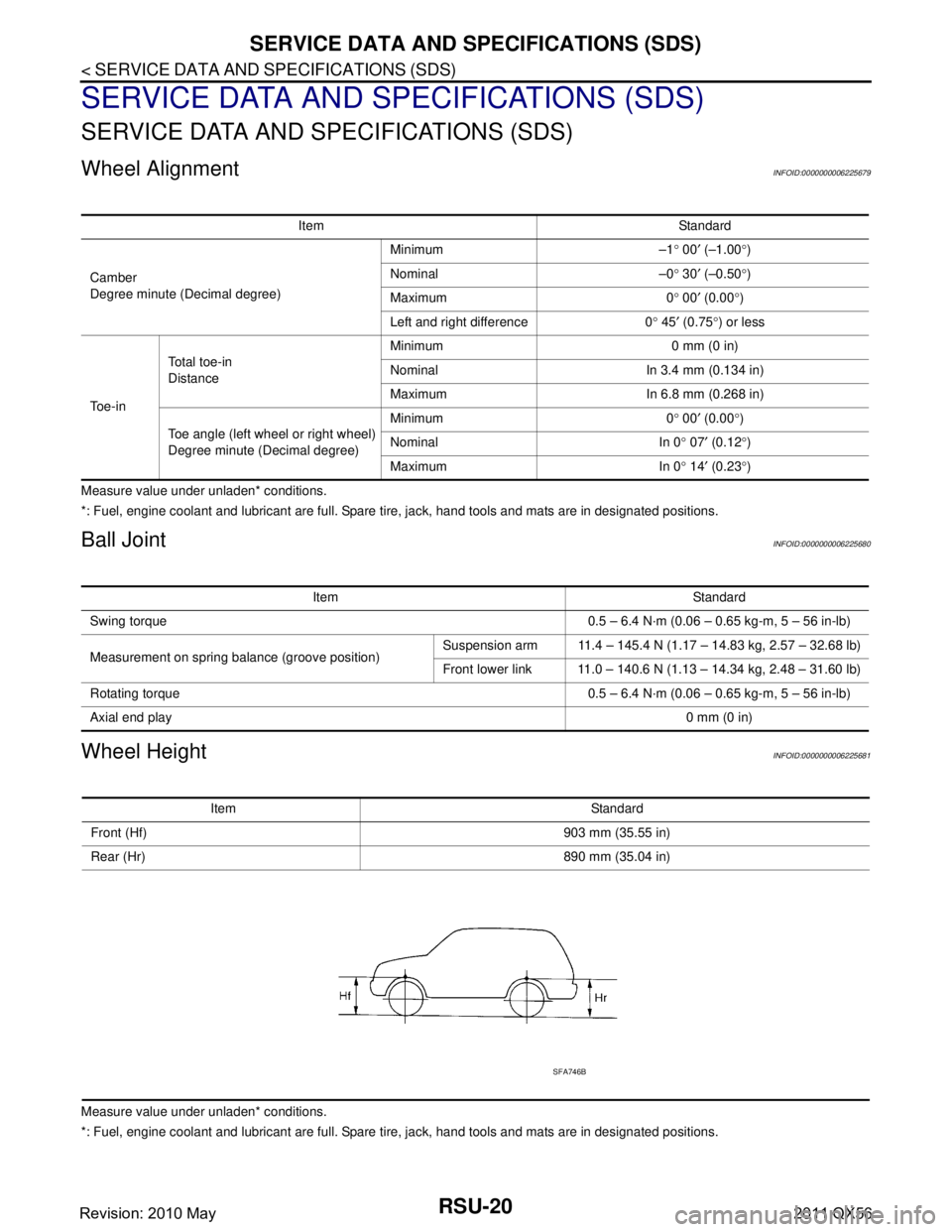
RSU-20
< SERVICE DATA AND SPECIFICATIONS (SDS)
SERVICE DATA AND SPECIFICATIONS (SDS)
SERVICE DATA AND SPECIFICATIONS (SDS)
SERVICE DATA AND SPECIFICATIONS (SDS)
Wheel AlignmentINFOID:0000000006225679
Measure value under unladen* conditions.
*: Fuel, engine coolant and lubricant are full. Spare tire, jack, hand tools and mats are in designated positions.
Ball JointINFOID:0000000006225680
Wheel HeightINFOID:0000000006225681
Measure value under unladen* conditions.
*: Fuel, engine coolant and lubricant are full. Spare tire, jack, hand tools and mats are in designated positions.Item Standard
Camber
Degree minute (Decimal degree) Minimum –1
° 00 ′ (–1.00 °)
Nominal –0 ° 30 ′ (–0.50 °)
Maximum 0 ° 00 ′ (0.00 °)
Left and right difference 0 ° 45 ′ (0.75 °) or less
To e - i n Total toe-in
Distance
Minimum 0 mm (0 in)
Nominal In 3.4 mm (0.134 in)
Maximum In 6.8 mm (0.268 in)
Toe angle (left wheel or right wheel)
Degree minute (Decimal degree) Minimum 0
° 00 ′ (0.00 °)
Nominal In 0 ° 07 ′ (0.12 °)
Maximum In 0 ° 14 ′ (0.23 °)
Item Standard
Swing torque 0.5 – 6.4 N·m (0.06 – 0.65 kg-m, 5 – 56 in-lb)
Measurement on spring balance (groove position) Suspension arm 11.4 – 145.4 N (1.17 – 14.83 kg, 2.57 – 32.68 lb)
Front lower link 11.0 – 140.6 N (1.13 – 14.34 kg, 2.48 – 31.60 lb)
Rotating torque 0.5 – 6.4 N·m (0.06 – 0.65 kg-m, 5 – 56 in-lb)
Axial end play 0 mm (0 in)
Item Standard
Front (Hf) 903 mm (35.55 in)
Rear (Hr) 890 mm (35.04 in)
SFA746B
Revision: 2010 May2011 QX56
Page 5082 of 5598
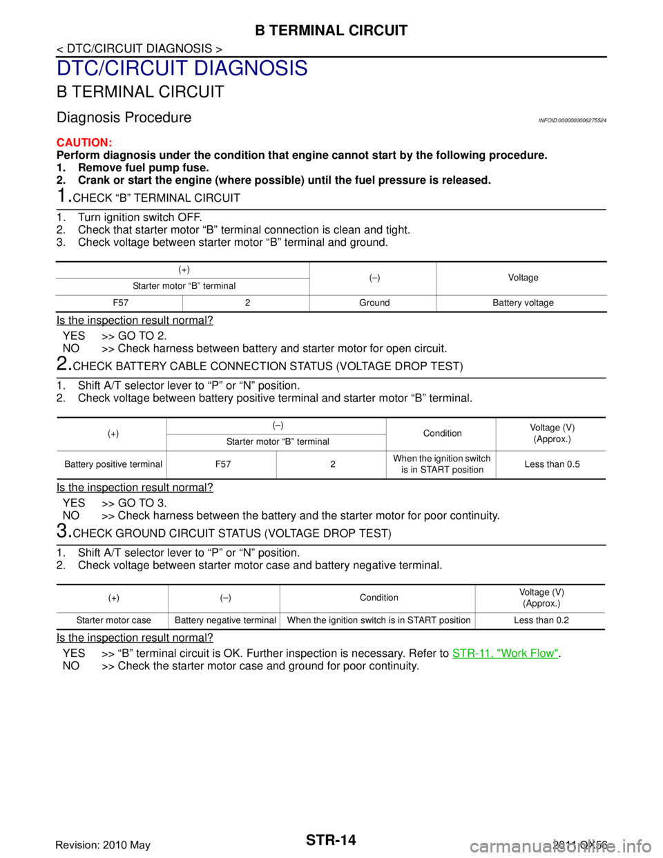
STR-14
< DTC/CIRCUIT DIAGNOSIS >
B TERMINAL CIRCUIT
DTC/CIRCUIT DIAGNOSIS
B TERMINAL CIRCUIT
Diagnosis ProcedureINFOID:0000000006275524
CAUTION:
Perform diagnosis under the condition that engine cannot start by the following procedure.
1. Remove fuel pump fuse.
2. Crank or start the engine (where possi ble) until the fuel pressure is released.
1.CHECK “B” TERMINAL CIRCUIT
1. Turn ignition switch OFF.
2. Check that starter motor “B” terminal connection is clean and tight.
3. Check voltage between starter motor “B” terminal and ground.
Is the inspection result normal?
YES >> GO TO 2.
NO >> Check harness between battery and starter motor for open circuit.
2.CHECK BATTERY CABLE CONNECTION STATUS (VOLTAGE DROP TEST)
1. Shift A/T selector lever to “P” or “N” position.
2. Check voltage between battery positive terminal and starter motor “B” terminal.
Is the inspection result normal?
YES >> GO TO 3.
NO >> Check harness between the battery and the starter motor for poor continuity.
3.CHECK GROUND CIRCUIT STATUS (VOLTAGE DROP TEST)
1. Shift A/T selector lever to “P” or “N” position.
2. Check voltage between starter motor case and battery negative terminal.
Is the inspection result normal?
YES >> “B” terminal circuit is OK. Further inspection is necessary. Refer to STR-11, "Work Flow".
NO >> Check the starter motor case and ground for poor continuity.
(+) (–) Voltage
Starter motor “B” terminal
F57 2 Ground Battery voltage
(+) (–)
ConditionVoltage (V)
(Approx.)
Starter motor “B” terminal
Battery positive terminal F57 2 When the ignition switch
is in START position Less than 0.5
(+) (–) Condition Voltage (V)
(Approx.)
Starter motor case Battery negative terminal When the ignition switch is in START position Less than 0.2
Revision: 2010 May2011 QX56
Page 5083 of 5598
S CONNECTOR CIRCUITSTR-15
< DTC/CIRCUIT DIAGNOSIS >
C
DE
F
G H
I
J
K L
M A
STR
NP
O
S CONNECTOR CIRCUIT
Diagnosis ProcedureINFOID:0000000006275525
CAUTION:
Perform diagnosis under the cond
ition that engine cannot start by the following procedure.
1. Remove fuel pump fuse.
2. Crank or start the engine (where possi ble) until the fuel pressure is released.
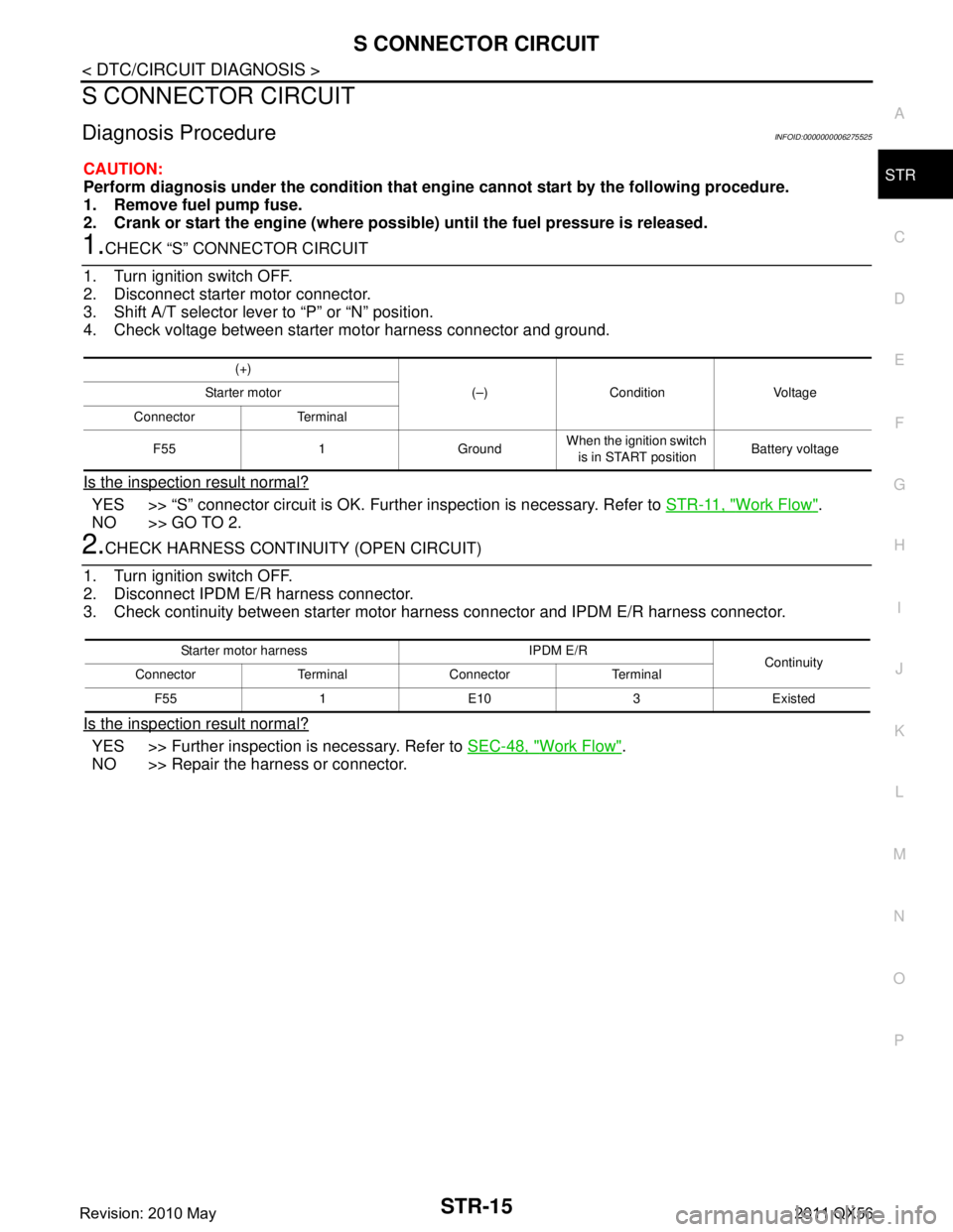
1.CHECK “S” CONNECTOR CIRCUIT
1. Turn ignition switch OFF.
2. Disconnect starter motor connector.
3. Shift A/T selector lever to “P” or “N” position.
4. Check voltage between starter motor harness connector and ground.
Is the inspection result normal?
YES >> “S” connector circuit is OK. Furt her inspection is necessary. Refer to STR-11, "Work Flow".
NO >> GO TO 2.
2.CHECK HARNESS CONTI NUITY (OPEN CIRCUIT)
1. Turn ignition switch OFF.
2. Disconnect IPDM E/R harness connector.
3. Check continuity between starter motor harness connector and IPDM E/R harness connector.
Is the inspection result normal?
YES >> Further inspection is necessary. Refer to SEC-48, "Work Flow".
NO >> Repair the harness or connector.
(+)
(–) Condition Voltage
Starter motor
Connector Terminal
F55 1 Ground When the ignition switch
is in START position Battery voltage
Starter motor harness IPDM E/R
Continuity
Connector Terminal Connector Terminal
F55 1 E10 3 Existed
Revision: 2010 May2011 QX56