2011 INFINITI QX56 remote control
[x] Cancel search: remote controlPage 1539 of 5598
DLK-3
C
DE
F
G H
I
J
L
M A
B
DLK
N
O P
Diagnosis Procedure ...........................................
....
98
B2423 AUTOMATIC BACK DOOR MOTOR
OPERATION TIME .............................................
99
DTC Logic ........................................................... ....99
Diagnosis Procedure ...............................................99
B2424 CLOSURE CONDITION ........................100
DTC Logic ........................................................... ..100
Diagnosis Procedure .............................................100
Component Inspection ..........................................101
B2425 AUTOMATIC BACK DOOR CONTROL
UNIT ..................................................................
103
DTC Logic ........................................................... ..103
Diagnosis Procedure .............................................103
B2621 INSIDE ANTENNA ................................104
DTC Logic ........................................................... ..104
Diagnosis Procedure .............................................104
B2622 INSIDE ANTENNA ................................106
DTC Logic ........................................................... ..106
Diagnosis Procedure .............................................106
B2623 INSIDE ANTENNA ................................108
DTC Logic ........................................................... ..108
Diagnosis Procedure .............................................108
B2626 OUTSIDE ANTENNA ............................110
DTC Logic ........................................................... ..110
Diagnosis Procedure .............................................110
B2627 OUTSIDE ANTENNA ............................112
DTC Logic ........................................................... ..112
Diagnosis Procedure .............................................112
B2628 OUTSIDE ANTENNA ............................114
DTC Logic ........................................................... ..114
Diagnosis Procedure .............................................114
POWER SUPPLY AND GROUND CIRCUIT ....116
AUTOMATIC BACK DOOR CONTROL UNIT ...... ..116
AUTOMATIC BACK DOOR CONTROL UNIT : Di-
agnosis Procedure ................................................
116
DOOR SWITCH ................................................117
Component Function Check .............................. ..117
Diagnosis Procedure .............................................117
Component Inspection ..........................................119
BACK DOOR SWITCH .....................................120
Component Function Check .............................. ..120
Diagnosis Procedure .............................................120
Component Inspection ..........................................121
DOOR LOCK AND UNLOCK SWITCH ............122
DRIVER SIDE ........................................................ ..122
DRIVER SIDE : Component Function Check ......122
DRIVER SIDE : Diagnosis Procedure ...................122
PASSENGER SIDE ..................................................122
PASSENGER SIDE :
Component Function Check .............................. ..
122
PASSENGER SIDE : Diagnosis Procedure ..........122
DOOR LOCK ACTUATOR ..............................123
DRIVER SIDE ......................................................... ..123
DRIVER SIDE : Component Function Check ......123
DRIVER SIDE : Diagnosis Procedure ...................123
PASSENGER SIDE ..................................................124
PASSENGER SIDE :
Component Function Check .............................. ..
124
PASSENGER SIDE : Diagnosis Procedure ..........124
REAR LH ................................................................ ..125
REAR LH : Component Function Check ..............125
REAR LH : Diagnosis Procedure ...........................125
REAR RH ............................................................... ..126
REAR RH : Component Function Check .............126
REAR RH : Diagnosis Procedure ..........................126
FUEL LID LOCK ACTUATOR ........................128
Component Function Check ................................128
Diagnosis Procedure .............................................128
UNLOCK SENSOR .........................................130
Component Function Check ................................130
Diagnosis Procedure .............................................130
Component Inspection ...........................................131
DOOR KEY CYLINDER SWITCH ...................132
Component Function Check ..................................132
Diagnosis Procedure .............................................132
Component Inspection ...........................................133
REMOTE KEYLESS ENTRY RECEIVER .......134
Component Function Check ................................134
Diagnosis Procedure .............................................134
DOOR REQUEST SWITCH ............................137
Component Function Check ................................137
Diagnosis Procedure .............................................137
Component Inspection ...........................................138
BACK DOOR REQUEST SWITCH .................139
Component Function Check ................................139
Diagnosis Procedure .............................................139
Component Inspection ...........................................140
BACK DOOR OPENER SWITCH ...................141
Component Function Check ................................141
Diagnosis Procedure .............................................141
Component Inspection ...........................................142
INTELLIGENT KEY WARNING BUZZER .......143
Component Function Check ................................143
Diagnosis Procedure .............................................143
Component Inspection ...........................................144
INTELLIGENT KEY .........................................145
Revision: 2010 May2011 QX56
Page 1543 of 5598
DLK-7
C
DE
F
G H
I
J
L
M A
B
DLK
N
O P
Exploded View ....................................................
..
243
DOOR LOCK ......................................................... ..243
DOOR LOCK : Removal and Installation ..............243
INSIDE HANDLE ................................................... ..243
INSIDE HANDLE : Removal and Installation ........244
OUTSIDE HANDLE ............................................... ..244
OUTSIDE HANDLE : Removal and Installation ....244
BACK DOOR LOCK .........................................246
Exploded View .................................................... ..246
DOOR LOCK ......................................................... ..246
DOOR LOCK : Removal and Installation ..............246
TOUCH SENSOR .................................................. ..246
TOUCH SENSOR : Removal and Installation .......246
BACK DOOR SUPPORT ROD .............................. ..247
BACK DOOR SUPPORT ROD : Removal and In-
stallation ................................................................
247
EMERGENCY LEVER ........................................... ..247
EMERGENCY LEVER : Unlock procedures .........247
FUEL FILLER LID OPENER ............................248
Exploded View .................................................... ..248
Removal and Installation .......................................248
KEY CYLINDER ...............................................250
GLOVE BOX LID KEY CYLINDER ....................... ..250
GLOVE BOX LID KEY CYLINDER : Removal and
Installation .............................................................
250
CAB MOUNTING INSULATOR ........................251
Exploded View .................................................... ..251
Removal and Installation .......................................251
DOOR SWITCH ................................................254
Removal and Installation ..................................... ..254
DOOR REQUEST SWITCH ..............................255
DRIVER SIDE ........................................................ ..255
DRIVER SIDE : Removal and Installation .............255
PASSENGER SIDE .................................................255
PASSENGER SIDE : Removal and Installation .. ..255
BACK DOOR ......................................................... ..255
BACK DOOR : Removal and Installation ..............255
INSIDE KEY ANTENNA ..................................256
INSTRUMENT CENTER ........................................ ..256
INSTRUMENT CENTER : Removal and Installa-
tion .........................................................................
256
CONSOLE .............................................................. ..256
CONSOLE : Removal and Installation ...................256
LUGGAGE ROOM ................................................. ..256
LUGGAGE ROOM : Removal and Installation ......256
OUTSIDE KEY ANTENNA ..............................257
DRIVER SIDE ......................................................... ..257
DRIVER SIDE : Removal and Installation .............257
PASSENGER SIDE ..................................................257
PASSENGER SIDE : Removal and Installation .. ..257
BACK DOOR ......................................................... ..257
BACK DOOR : Removal and Installation ...............257
INTELLIGENT KEY WARNING BUZZER .......258
Removal and Installation .......................................258
REMOTE KEYLESS ENTRY RECEIVER .......259
Removal and Installation .......................................259
INTELLIGENT KEY BATTERY .......................260
Removal and Installation .......................................260
BACK DOOR CONTROL UNIT ......................261
Removal and Installation ..................................... ..261
AUTOMATIC BACK DOOR CONTROL MOD-
ULE ..................................................................
262
Removal and Installation .......................................262
AUTOMATIC BACK DOOR WARNING BUZZ-
ER ....................................................................
263
Removal and Installation .......................................263
AUTOMATIC BACK DOOR MAIN SWITCH ...264
Removal and Installation .......................................264
AUTOMATIC BACK DOOR CLOSE SWITCH .265
Removal and Installation ..................................... ..265
AUTOMATIC BACK DOOR SWITCH .............266
Removal and Installation .......................................266
Revision: 2010 May2011 QX56
Page 1548 of 5598
DLK-12
< SYSTEM DESCRIPTION >
COMPONENT PARTS
DOOR LOCK SYSTEM : Component Description
INFOID:0000000006225834
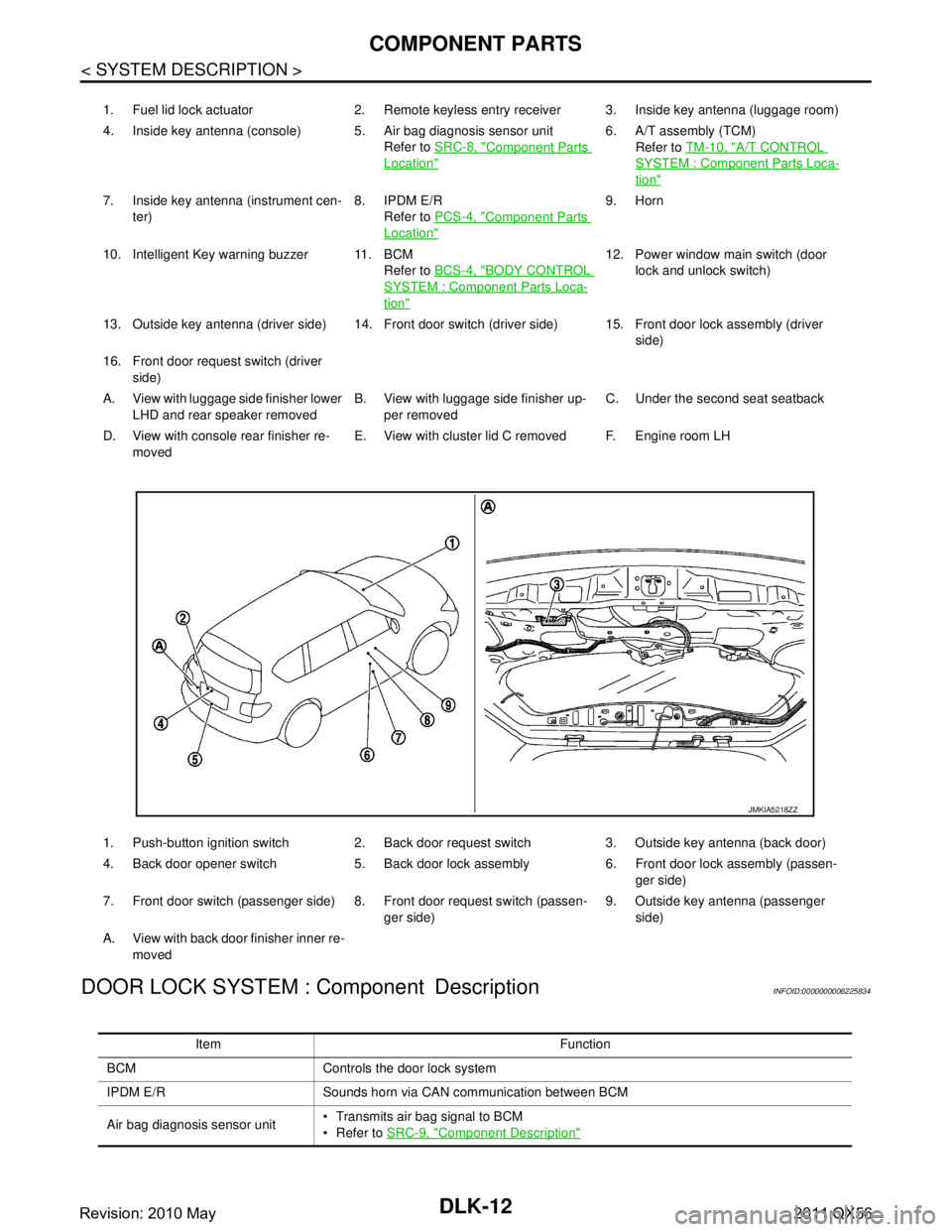
1. Fuel lid lock actuator 2. Remote keyless entry receiver 3. Inside key antenna (luggage room)
4. Inside key antenna (console) 5. Air bag diagnosis sensor unit Refer to SRC-8, "
Component Parts
Location"
6. A/T assembly (TCM)
Refer to TM-10, "
A/T CONTROL
SYSTEM : Component Parts Loca-
tion"
7. Inside key antenna (instrument cen-
ter) 8. IPDM E/R
Refer to PCS-4, "
Component Parts
Location"
9. Horn
10. Intelligent Key warning buzzer 11. BCM Refer to BCS-4, "
BODY CONTROL
SYSTEM : Component Parts Loca-
tion"
12. Power window main switch (door
lock and unlock switch)
13. Outside key antenna (driver side) 14. Front door switch (driver side) 15. Front door lock assembly (driver side)
16. Front door request switch (driver side)
A. View with luggage side finisher lower LHD and rear speaker removed B. View with luggage side finisher up-
per removed C. Under the second seat seatback
D. View with console rear finisher re- moved E. View with cluster lid C removed F. Engine room LH
1. Push-button ignition switch 2. Back door request switch 3. Outside key antenna (back door)
4. Back door opener switch 5. Back door lock assembly 6. Front door lock assembly (passen- ger side)
7. Front door switch (passenger side) 8. Front door request switch (passen- ger side)9. Outside key antenna (passenger
side)
A. View with back door finisher inner re- moved
JMKIA5218ZZ
Item Function
BCM Controls the door lock system
IPDM E/R Sounds horn via CAN communication between BCM
Air bag diagnosis sensor unit Transmits air bag signal to BCM
Refer to
SRC-9, "
Component Description"
Revision: 2010 May2011 QX56
Page 1549 of 5598
COMPONENT PARTSDLK-13
< SYSTEM DESCRIPTION >
C
DE
F
G H
I
J
L
M A
B
DLK
N
O P
AUTOMATIC BACK DOOR SYSTEM
Combination meter Displays each operation method guide and warning for system malfunction
Performs operation method guide and warning with buzzer
Transmits vehicle speed signal to CAN communication line
TCM Transmits shift position signal to BCM via CAN communication line
Remote keyless entry receiver Receives Intelligent Key operation and transmits to BCM
Inside key antenna Detects if Intelligent Key is inside the vehicle
Outside key antenna Detects if Intelligent Key is outside the vehicle
Push-button ignition switch Inputs push-button ignition switch ON/OFF condition to BCM
Door switch Inputs door open/close condition to BCM
Door lock and unlock switch Detects if door lock and unlock switch is press/release
Integrated in the power window main switch and front power window switch (passenger
side)
Door request switch Detects if each door request switch is press/release
Integrated in the outside handle (driver side, passenger side) and back door opener
switch assembly
Intelligent Key warning buzzer Warns the user of the lock/unlock condition and inappropriate operations with the buzzer
sound
Intelligent Key The following functions are available when having and carrying electronic ID
Door lock/unlock
Engine start
Remote control entry function is available when operating on button
Hazard warning lamp Warns the user of the lock/unlock condition and inappropriate operations with the lamps
blink
Door lock actuator Output lock/unlock signal from BCM and locks/unlocks each door
Fuel lid lock actuator Output lock/unlock signal from BCM and locks/unlocks fuel filler lid Item Function
Revision: 2010 May2011 QX56
Page 1554 of 5598
DLK-18
< SYSTEM DESCRIPTION >
SYSTEM (INTELLIGENT KEY SYSTEM)
SYSTEM (INTELLIGENT KEY SYSTEM)
INTELLIGENT KEY SYSTEM
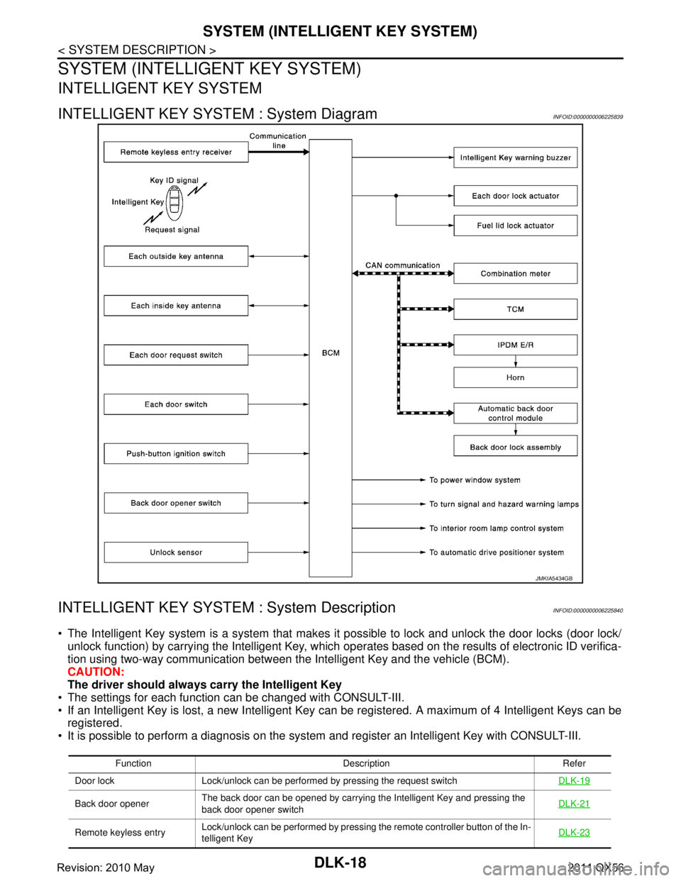
INTELLIGENT KEY SYSTEM : System DiagramINFOID:0000000006225839
INTELLIGENT KEY SYSTEM : System DescriptionINFOID:0000000006225840
The Intelligent Key system is a syste m that makes it possible to lock and unlock the door locks (door lock/
unlock function) by carrying the Intelligent Key, which operates based on the results of electronic ID verifica-
tion using two-way communication between the Intelligent Key and the vehicle (BCM).
CAUTION:
The driver should always carry the Intelligent Key
The settings for each function can be changed with CONSULT-III.
If an Intelligent Key is lost, a new Intelligent Key can be registered. A maximum of 4 Intelligent Keys can be
registered.
It is possible to perform a diagnosis on the system and register an Intelligent Key with CONSULT-III.
JMKIA5434GB
Function Description Refer
Door lock Lock/unlock can be performed by pressing the request switch DLK-19
Back door openerThe back door can be opened by carrying the Intelligent Key and pressing the
back door opener switch DLK-21
Remote keyless entry
Lock/unlock can be performed by pressing the remote controller button of the In-
telligent Key DLK-23
Revision: 2010 May2011 QX56
Page 1555 of 5598

SYSTEM (INTELLIGENT KEY SYSTEM)
DLK-19
< SYSTEM DESCRIPTION >
C
D E
F
G H
I
J
L
M A
B
DLK
N
O P
DOOR LOCK FUNCTION
DOOR LOCK FUNCTION : System DiagramINFOID:0000000006225841
DOOR LOCK FUNCTION : System DescriptionINFOID:0000000006225842
Only when pressing the door request switch, it is possi ble to lock and unlock the door by carrying the Intelli-
gent Key.
OPERATION DESCRIPTION
When the BCM detects that each door request switch is pressed, it activates the outside key antenna and
inside key antenna corresponding to the pressed door reques t switch and transmits the request signal to the
Intelligent Key. And then, check that the Intelligent Key is near the door.
If the Intelligent Key is within the outside key ant enna detection area, it receives the request signal and
transmits the key ID signal to the BCM via remote keyless entry receiver.
BCM receives the key ID signal and compares it with the registered key ID.
BCM locks/unlocks each doors (except back door).
BCM sounds Intelligent Key warning buzzer (lock: 2 ti mes, unlock: 1 time) and blinks hazard warning lamps
(lock: 2 times, unlock: 1 time) at the same time as a reminder.
Key reminder The key reminder buzzer sounds a warning if the door is locked with the key left
inside the vehicle DLK-26
Welcome lightWhen the Intelligent Key is carried, and vehicle doors are approached, the BCM
illuminates interior room lamps and operates heart beat operation of the push-
button ignition switch DLK-26
Warning
If an action that does not meet the operating condition of the Intelligent Key sys-
tem is taken, the buzzer sounds to inform the driver DLK-27
Engine start The engine can be turned on while carrying the Intelligent Key
SEC-12
Interior room lamp control Interior room lamp is controlled according to door lock/unlock state INL-6
Power window Power window can be operated by Intelligent Key button operationPWC-8
Automatic drive positioner Automatic drive positioner system can be operated by door unlock operationADP-11
Panic alarm When Intelligent Key panic alarm button is pressed, horn soundsSEC-18
Function Description Refer
JMKIA5068GB
Revision: 2010 May2011 QX56
Page 1558 of 5598
DLK-22
< SYSTEM DESCRIPTION >
SYSTEM (INTELLIGENT KEY SYSTEM)
The back door open function can open the back door by pressing the back door opener switch while carryingthe Intelligent Key and all doors (except back door) are locked.
The back door open function enables the back door to be opened by pressing back door opener switch after
BCM transmits UNLOCK signal to each door.Refer to DLK-31, "
System Description".
BACK DOOR OPEN
While back door open in the permitted state, back door opens when back door opener switch is pressed after
back door request switch is operated. Back door open also can be operated according to the following proce-
dure.
When the BCM detects that back door opener switch is pressed, it activates the outside key antenna (back
door) and inside key antenna and transmits the request signal to the Intelligent Key. And then, check that the
Intelligent Key is near the back door.
If the Intelligent Key is within the outside key ant enna detection area, it receives the request signal and
transmits the key ID signal to the BCM via remote keyless entry receiver.
BCM receives the key ID signal and compares it with the registered key ID.
If the verification result is OK, BCM transmits the back door open request signal to automatic back door con- trol unit via CAN communication.
Automatic back door control unit transmits back door open request signal to back door lock assembly and
back door is open.
When the back door is open, automatic back door sys tem performs waiting operation for next back door
close operation.
The operation of then back door open is the same as the automatic back door system, refer to DLK-31,
"System Description".
OPERATION CONDITION
If the following conditions are not satisfied, ba ck door open operation is not performed even if the back door
opener switch is operated.
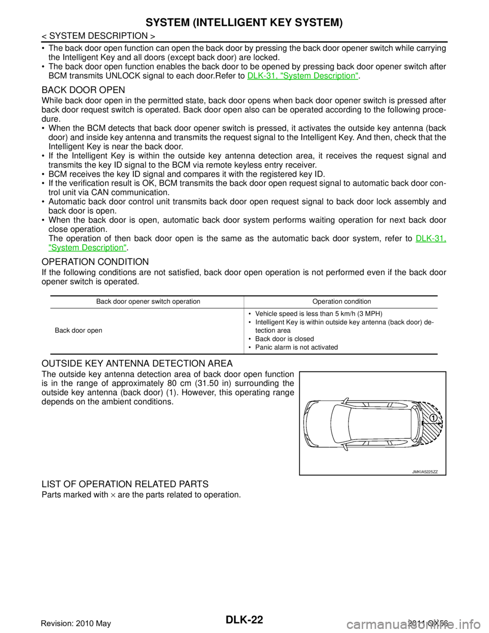
OUTSIDE KEY ANTENNA DETECTION AREA
The outside key antenna detection area of back door open function
is in the range of approximately 80 cm (31.50 in) surrounding the
outside key antenna (back door) (1). However, this operating range
depends on the ambient conditions.
LIST OF OPERATION RELATED PARTS
Parts marked with × are the parts related to operation.
Back door opener switch operation Operation condition
Back door open Vehicle speed is less than 5 km/h (3 MPH)
Intelligent Key is within outside key antenna (back door) de-
tection area
Back door is closed
Panic alarm is not activated
JMKIA5225ZZ
Revision: 2010 May2011 QX56
Page 1559 of 5598
SYSTEM (INTELLIGENT KEY SYSTEM)
DLK-23
< SYSTEM DESCRIPTION >
C
D E
F
G H
I
J
L
M A
B
DLK
N
O P
REMOTE KEYLESS ENTRY FUNCTION
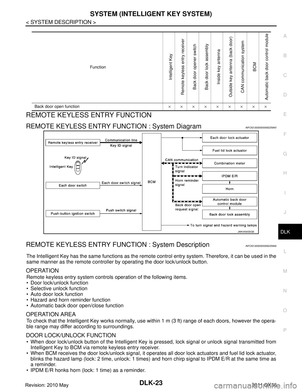
REMOTE KEYLESS ENTRY F UNCTION : System DiagramINFOID:0000000006225845
REMOTE KEYLESS ENTRY FUNCT ION : System DescriptionINFOID:0000000006225846
The Intelligent Key has the same functions as the remote control entry system. Therefore, it can be used in the
same manner as the remote controller by operating the door lock/unlock button.
OPERATION
Remote keyless entry system controls operation of the following items.
Door lock/unlock function
Selective unlock function
Auto door lock function
Hazard and horn reminder function
Automatic back door open/close function
OPERATION AREA
To check that the Intelligent Key works normally, use within 1 m (3 ft) range of each doors, however the opera-
ble range may differ according to surroundings.
DOOR LOCK/UNLOCK FUNCTION
When door lock/unlock button of the Intelligent Key is pr essed, lock signal or unlock signal transmitted from
Intelligent Key to BCM via remote keyless entry receiver.
When BCM receives the door lock/unlock signal, it operates all door lock actuators and fuel lid lock actuator,
blinks the hazard lamp (lock: 2 time, unlock: 1 times) and horn chirp signal to IPDM E/R at the same time as
a reminder.
IPDM E/R honks horn (lock: 1 time) as a reminder.
Function
Intelligent Key
Remote keyless entry receiver Back door opener switch
Back door lock assembly Inside key antenna
Outside key antenna (back door) CAN communication system BCM
Automatic back door control module
Back door open function ×××××××××
JMKIA5435GB
Revision: 2010 May2011 QX56