2011 INFINITI QX56 change time
[x] Cancel search: change timePage 1561 of 5598

SYSTEM (INTELLIGENT KEY SYSTEM)
DLK-25
< SYSTEM DESCRIPTION >
C
D E
F
G H
I
J
L
M A
B
DLK
N
O P
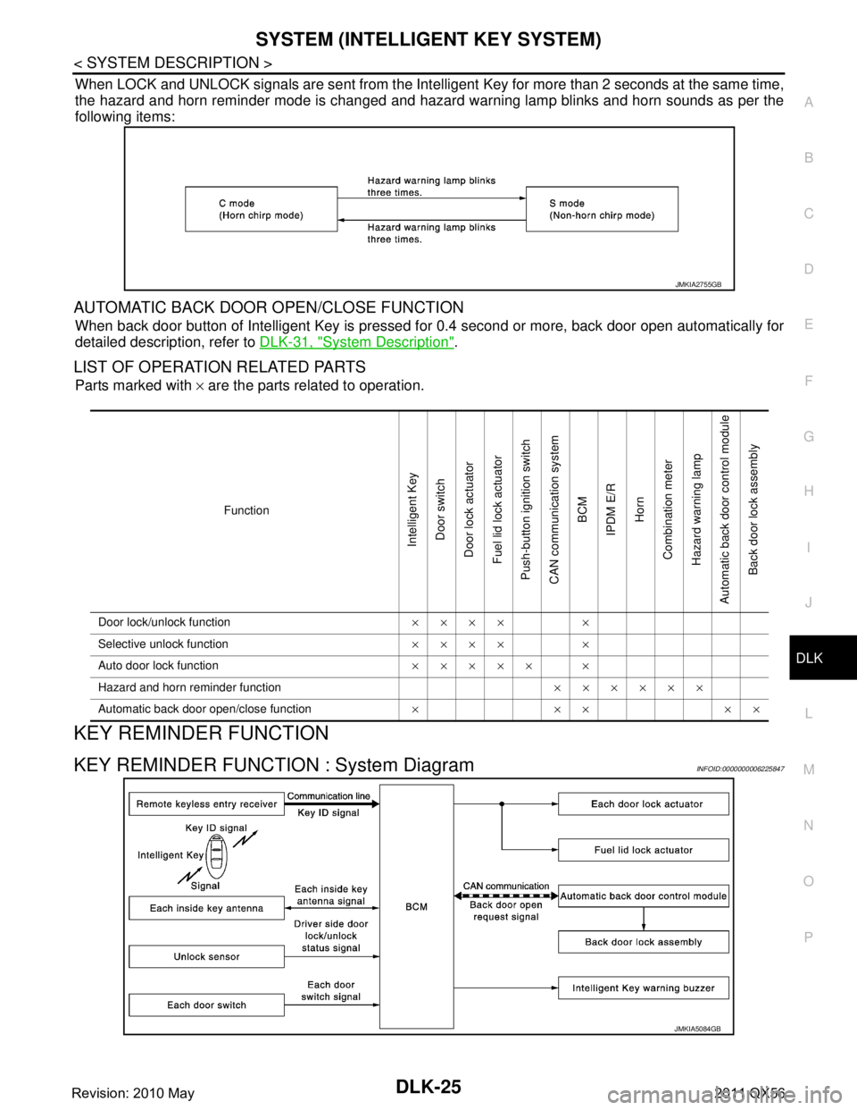
When LOCK and UNLOCK signals are sent from the Intelligent Key for more than 2 seconds at the same time,
the hazard and horn reminder mode is changed and hazard warning lamp blinks and horn sounds as per the
following items:
AUTOMATIC BACK DOOR OPEN/CLOSE FUNCTION
When back door button of Intelligent Key is pressed fo r 0.4 second or more, back door open automatically for
detailed description, refer to DLK-31, "
System Description".
LIST OF OPERATION RELATED PARTS
Parts marked with × are the parts related to operation.
KEY REMINDER FUNCTION
KEY REMINDER FUNCTION : System DiagramINFOID:0000000006225847
JMKIA2755GB
Function
Intelligent Key
Door switch
Door lock actuator
Fuel lid lock actuator
Push-button ignition switch
CAN communication system BCM
IPDM E/R
Horn
Combination meter
Hazard warning lamp
Automatic back door control module
Back door lock assembly
Door lock/unlock function ×××× ×
Selective unlock function ×××× ×
Auto door lock function ××××× ×
Hazard and horn reminder function ××××××
Automatic back door open/close function ×××××
JMKIA5084GB
Revision: 2010 May2011 QX56
Page 1563 of 5598

SYSTEM (INTELLIGENT KEY SYSTEM)
DLK-27
< SYSTEM DESCRIPTION >
C
D E
F
G H
I
J
L
M A
B
DLK
N
O P
When the BCM detects that the Intelligent Key is within the outside key antenna detection area. BCM trans-
mits the request signal to the Intelligent Key and check it is near the door.
Intelligent Key receives the request signal and transmits the key ID signal to the BCM via remote keyless
entry receiver.
BCM receives the key ID signal and compares it with the registered key ID.
BCM illuminates lamps that are set, when key ID verification is OK.
TIMER FUNCTION
BCM can operate welcome light function, using the timer function, for 9 days, after key switch is turned OFF.
The timer function resets when the engine is started
*.Operating period of timer function may differ depending
on battery size.
*: Timer function does not stop if another Intelligent Key that has a different key ID is detected within the inte-
rior antenna detection area, when starting the engine.
OPERATION CONDITION
If the following condition are satisfi ed, welcome light function is operated.
OUTSIDE KEY ANTENNA DETECTION AREA
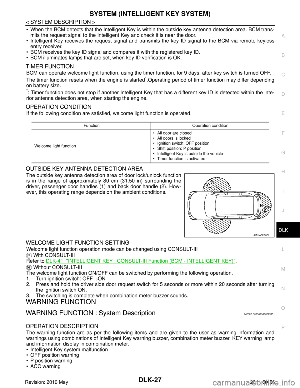
The outside key antenna detection area of door lock/unlock function
is in the range of approximately 80 cm (31.50 in) surrounding the
driver, passenger door handles (1) and back door handle (2). How-
ever, this operating range depends on the ambient conditions.
WELCOME LIGHT FUNCTION SETTING
Welcome light function operation mode can be changed using CONSULT-III
With CONSULT-III
Refer to DLK-41, "
INTELLIGENT KEY : CONSULT-III F unction (BCM - INTELLIGENT KEY)".
Without CONSULT-III
The welcome light function ON/OFF can be s witched by performing the following operation.
1. Turn ignition switch: OFF →ON
2. Press and hold the driver side door request switch for 5 seconds or more within 20 seconds after turning the ignition switch ON.
3. The switching is complete when combination meter buzzer sounds.
WARNING FUNCTION
WARNING FUNCTION : System DescriptionINFOID:0000000006225851
OPERATION DESCRIPTION
The warning function are as per the following items and are given to the user as warning information and
warnings using combinations of Intelligent Key warning buzzer, combination meter buzzer, KEY warning lamp
and information display in combination meter.
Intelligent Key system malfunction
OFF position warning
P position warning
ACC warning
Function Operation condition
Welcome light function All door are closed
All doors is locked
Ignition switch: OFF position
Shift position: P position
Intelligent Key is outside the vehicle
Timer function is activated
JMKIA5224ZZ
Revision: 2010 May2011 QX56
Page 1574 of 5598

DLK-38
< SYSTEM DESCRIPTION >
DIAGNOSIS SYSTEM (BCM)
DIAGNOSIS SYSTEM (BCM)
COMMON ITEM
COMMON ITEM : CONSULT-III Function (BCM - COMMON ITEM)INFOID:0000000006307583
APPLICATION ITEM
CONSULT-III performs the following functions via CAN communication with BCM.
SYSTEM APPLICATION
BCM can perform the following functions for each system.
NOTE:
It can perform the diagnosis modes except the following for all sub system selection items.
×: Applicable item
*: This item is indicated, but not used.
FREEZE FRAME DATA (FFD)
The BCM records the following vehicle condition at the time a particular DTC is detected, and displays on
CONSULT-III.
Diagnosis mode Function Description
Work Support Changes the setting for each system function.
Self Diagnostic Result Displays the diagnosis results judged by BCM. Refer to BCS-57, "
DTCIndex".
CAN Diag Support Monitor Monitors the reception status of CAN communication viewed from BCM. Refer to CONSULT-III opera-
tion manual.
Data Monitor The BCM input/output signals are displayed.
Active Test The signals used to activate ea ch device are forcibly supplied from BCM.
Ecu Identification The BCM part number is displayed.
Configuration Read and save the vehicle specification.
Write the vehicle specification when replacing BCM.
System Sub system selection item Diagnosis mode
Work Support Data Monitor Active Test
Door lock DOOR LOCK ×××
Rear window defogger REAR DEFOGGER ××
Warning chime BUZZER ××
Interior room lamp timer INT LAMP ×××
Exterior lamp HEAD LAMP ×××
Wiper and washer WIPER ×××
Turn signal and hazard warning lamps FLASHER ×××
— AIR CONDITONER* ××
Intelligent Key system
Engine start system INTELLIGENT KEY
×××
Combination switch COMB SW ×
Body control system BCM ×
IVIS IMMU ×××
Interior room lamp battery saver BATTERY SAVER ×××
Back door TRUNK ×
Vehicle security system THEFT ALM ×××
RAP system RETAINED PWR ×
Signal buffer system SIGNAL BUFFER ××
Revision: 2010 May2011 QX56
Page 1577 of 5598

DIAGNOSIS SYSTEM (BCM)DLK-41
< SYSTEM DESCRIPTION >
C
DE
F
G H
I
J
L
M A
B
DLK
N
O P
INTELLIGENT KEY : CONSULT-III Fu nction (BCM - INTELLIGENT KEY)INFOID:0000000006225856
WORK SUPPORT
Monitor item Description
INSIDE ANT DIAGNOSIS This function allows inside key antenna self-diagnosis
LOCK/UNLOCK BY I-KEY Door lock/unlock function by door request switch mode can be changed to operation in this
mode
On: Operate
Off: Non-operation
ENGINE START BY I-KEY Engine start function mode can be changed to operation with this mode
On: Operate
Off: Non-operation
TRUNK/GLASS HATCH OPEN Buzzer reminder function mode by back door opener switch can be changed to operation with
this mode
On: Operate
Off: Non-operation
PANIC ALARM SET Panic alarm button pressing time on Intelligent Key button can be selected from the following
with this mode
MODE 1: 0.5 sec
MODE 2: Non-operation
MODE 3: 1.5 sec
TRUNK OPEN DELAY Back door open button pressing to Intelligent Key button can be selected as per the following
in this mode
MODE 1: Press and hold
MODE 2: Press twice
MODE 3: Press and hold, or press twice
LO- BATT OF KEY FOB WARN Intelligent Key low battery warning mode can be changed to operation with this mode
On: Operate
Off: Non-operation
ANTI KEY LOCK IN FUNCTI Key reminder function mode can be changed to operation with this mode
On: Operate
Off: Non-operation
HAZARD ANSWER BACK Hazard reminder function mode by door request switch and Intelligent Key button can be se-
lected from the following with this mode
Lock Only: Door lock operation only
Unlock Only: Door unlock operation only
Lock/Unlock: Lock and unlock operation
Off: Non-operation
ANS BACK I-KEY LOCK Buzzer reminder function (lock operation) mode by door request switch can be selected from
the following with this mode
Horn Chirp: Sound horn
Buzzer: Sound Intelligent Key warning buzzer
Off: Non-operation
ANS BACK I-KEY UNLOCK Buzzer reminder function (unlock operation) mode by door request switch can be changed to
operation with this mode
On: Operate
Off: Non-operation
SHORT CRANKING OUTPUT Starter motor can operate during the times below
70 msec
100 msec
200 msec
CONFIRM KEY FOB ID It can be checked wh ether Intelligent Key ID code is registered or not in this mode
Revision: 2010 May2011 QX56
Page 1578 of 5598

DLK-42
< SYSTEM DESCRIPTION >
DIAGNOSIS SYSTEM (BCM)
SELF-DIAG RESULT
Refer to BCS-57, "DTCIndex".
DATA MONITOR
AUTO LOCK SET Auto door lock operation time can be changed in this mode
MODE 1: OFF
MODE 2: 30 sec
MODE 3: 1 minute
MODE 4: 2 minutes
MODE 5: 3 minutes
MODE 6: 4 minutes
MODE 7: 5 minutes
HORN WITH KEYLESS LOCK Horn reminder function mode by Intelligent Key button can be selected from the following with
this mode
On: Operate
Off: Non-operation
PW DOWN SET Unlock button pressing time on Intelligent Key button can be selected from the following with
this mode
MODE 1: 3 sec
MODE 2: Non-operation
MODE 3: 5 sec
WELCOME LIGHT SELECT Welcome light function mode can be selected from the following with this mode
Puddle/Outside Handle
Room lamp
Head & Tail Lamps (this item is displayed, but cannot be used)
Heart Beat
WELCOME LIGHT OP SET Welcome light function mode can be changed to operation with this mode
On: Operate
Off: Non-operation
Monitor item Description
Monitor Item Condition
REQ SW -DR Indicates [On/Off] condition of door request switch (driver side)
REQ SW -AS Indicates [On/Off] condition of door request switch (passenger side)
REQ SW -BD/TR Indicates [On/Off] condition of back door request switch
PUSH SW Indicates [On/Off] condition of push-button ignition switch
CLUTCH SW NOTE:
This item is displayed, but cannot be monitored
BRAKE SW 1 Indicates [On/Off]* condition of stop lamp switch power supply
BRAKE SW 2 Indicates [On/Off] condition of stop lamp switch
DETE/CANCL SW Indicates [On/Off] condition of P position
SFT PN/N SW Indicates [On/Off] condition of P or N position
S/L -LOCK Indicates [On/Off] condition of steering lock unit (LOCK)
S/L -UNLOCK Indicates [On/Off] condition of steering lock unit (UNLOCK)
S/L RELAY -F/B Indicates [On/Off] condition of steering lock relay
UNLK SEN -DR Indicates [On/Off] condition of driver door UNLOCK status
PUSH SW -IPDM Indicates [On/Off] condition of push-button ignition switch
IGN RLY1 -F/B Indicates [On/Off] condition of ignition relay 1
DETE SW -IPDM Indicates [On/Off] condition of P position
SFT PN -IPDM Indicates [On/Off] condition of P or N position
SFT P -MET Indicates [On/Off] condition of P position
SFT N -MET Indicates [On/Off] condition of N position
ENGINE STATE Indicates [Stop/Stall/Crank/Run] condition of engine states
Revision: 2010 May2011 QX56
Page 1628 of 5598

DLK-92
< DTC/CIRCUIT DIAGNOSIS >
B2419 OPEN SWITCH
B2419 OPEN SWITCH
DTC LogicINFOID:0000000006225891
DTC DETECTION LOGIC
DTC CONFIRMATION PROCEDURE
1.PERFORM DTC CONFIRMATION PROCEDURE
1. Turn ignition switch ON.
2. Check “Self Diagnostic Result” mode of “AUTOMAT IC BACK DOOR CONTROL UNIT” using CONSULT-
III.
Is DTC detected?
YES >> Refer to DLK-92, "Diagnosis Procedure".
NO >> INSPECTION END
Diagnosis ProcedureINFOID:0000000006225892
1.CHECK OPEN SWITCH SIGNAL
1. Select “AUTOMATIC BACK DOOR CONTROL UNIT” using CONSULT-III.
2. Select “OPEN SW” in “DATA MONITOR” mode.
3. Check that the function operates normall y according to the following conditions.
Is the inspection result normal?
YES >> GO TO 6.
NO >> GO TO 2.
2.CHECK AUTOMATIC BACK DOOR CONTROL MODULE OUTPUT SIGNAL
1. Turn ignition switch OFF.
2. Disconnect back door lock assembly connector.
3. Check voltage between back door lock assembly harness connector and ground.
Is the inspection result normal?
YES >> GO TO 4.
NO >> GO TO 3.
DTC CONSULT-III display
description DTC detecting condition Possible cause
B2419 OPEN SW When the automatic back door control unit detects
any of the following conditions
The change of open switch cannot be detected
for 1 second or more after starting the closure
open output for the 3rd time in a row
The change of open switch cannot be detected for 0.5 second or more after starting the closure
close output for the 3rd time in a row
The condition that the open switch is in the ON position and the close switch is in the OFF posi-
tion is detected when starting the closure open/
close output for the 3rd time in a row Open switch
Harness or connectors
(Open switch circuit is open or
shorted)
Automatic back door control mod- ule
Monitor item Condition Status
OPEN SW Back door Fully closed/Half latch OFF
Open ON
(+)
(–)Voltag e
(Approx.)
Back door lock assembly
Connector Terminal D157 4 Ground Battery voltage
Revision: 2010 May2011 QX56
Page 1631 of 5598

B2420 CLOSE SWITCHDLK-95
< DTC/CIRCUIT DIAGNOSIS >
C
DE
F
G H
I
J
L
M A
B
DLK
N
O P
B2420 CLOSE SWITCH
DTC LogicINFOID:0000000006225894
DTC DETECTION LOGIC
DTC CONFIRMATION PROCEDURE
1.PERFORM DTC CONFIRMATION PROCEDURE
1. Turn ignition switch ON.
2. Check “Self Diagnostic Result” mode of “AUTOMAT IC BACK DOOR CONTROL UNIT” using CONSULT-
III.
Is DTC detected?
YES >> Refer to DLK-95, "Diagnosis Procedure".
NO >> INSPECTION END
Diagnosis ProcedureINFOID:0000000006225895
1.CHECK CLOSE SWITCH SIGNAL
1. Select “AUTOMATIC BACK DOOR CONTROL UNIT” using CONSULT-III.
2. Select “CLOSE SW” in “DATA MONITOR” mode.
3. Check that the function operates normall y according to the following conditions.
Is the inspection result normal?
YES >> GO TO 6.
NO >> GO TO 2.
2.CHECK AUTOMATIC BACK DOOR CONTROL MODULE OUTPUT SIGNAL
1. Turn ignition switch OFF.
2. Disconnect back door lock assembly connector.
3. Check voltage between back door lock assembly harness connector and ground.
Is the inspection result normal?
YES >> GO TO 4.
NO >> GO TO 3.
3.CHECK CLOSE SWITCH CIRCUIT
1. Disconnect automatic back door control module connector.
2. Check continuity between automatic back door control module harness connector and back door lock
assembly harness connector.
DTC CONSULT-III display
description DTC detecting condition Possible cause
B2420 CLOSE SW When the automatic back door control unit detects
any of the following conditions
The change of close switch cannot be detected
for 3 second or more after starting the closure
close output for the 3rd time in a row Close switch
Harness or connectors
(Close switch circuit is open or
shorted)
Automatic back door control mod- ule
Monitor item Condition Status
CLOSE SW Back door Open/Half latch OFF
Fully closed ON
(+)
(–)Voltag e
(Approx.)
Back door lock assembly
Connector Terminal D157 5 Ground Battery voltage
Revision: 2010 May2011 QX56
Page 1748 of 5598

DLK-212
< SYMPTOM DIAGNOSIS >
SQUEAK AND RATTLE TROUBLE DIAGNOSES
Most of these incidents can be repaired by adjusting, securing or insulating the item(s) or component(s) caus-
ing the noise.
SUNROOF/HEADLINING
Noises in the sunroof/headlining area c an often be traced to one of the following:
1. Sunroof lid, rail, linkage or seals making a rattle or light knocking noise
2. Sunvisor shaft shaking in the holder
3. Front or rear windshield touching headlining and squeaking
Again, pressing on the components to stop the noise while duplicating the conditions can isolate most of these
incidents. Repairs usually consist of insulating with felt cloth tape.
SEATS
When isolating seat noise it is important to note t he position the seat is in and the load placed on the seat
when the noise is present. These conditions should be duplicated when verifying and isolating the cause of
the noise.
Cause of seat noise include:
1. Headrest rods and holder
2. A squeak between the seat pad cushion and frame
3. Rear seatback lock and bracket
These noises can be isolated by moving or pressing on the suspected components while duplicating the con-
ditions under which the noise occurs. Most of thes e incidents can be repaired by repositioning the component
or applying urethane tape to the contact area.
UNDERHOOD
Some interior noise may be caused by components under the hood or on the engine wall. The noise is then
transmitted into the passenger compartment.
Causes of transmitted underhood noise include:
1. Any component mounted to the engine wall
2. Components that pass through the engine wall
3. Engine wall mounts and connectors
4. Loose radiator mounting pins
5. Hood bumpers out of adjustment
6. Hood striker out of adjustment
These noises can be difficult to isolate since they cannot be reached from the interior of the vehicle. The best
method is to secure, move or insulate one component at a time and test drive the \
vehicle. Also, engine RPM
or load can be changed to isolate the noise. Repairs can usually be made by moving, adjusting, securing, or
insulating the component causing the noise.
Revision: 2010 May2011 QX56