2011 INFINITI QX56 Fuel
[x] Cancel search: FuelPage 1560 of 5598
DLK-24
< SYSTEM DESCRIPTION >
SYSTEM (INTELLIGENT KEY SYSTEM)
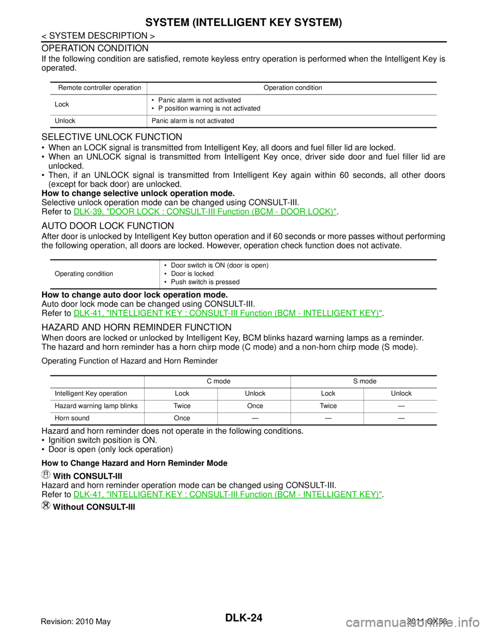
OPERATION CONDITION
If the following condition are satisfied, remote keyless entry operation is performed when the Intelligent Key is
operated.
SELECTIVE UNLOCK FUNCTION
When an LOCK signal is transmitted from Intelligent Key, all doors and fuel filler lid are locked.
When an UNLOCK signal is transmitted from Intelligent Key once, driver side door and fuel filler lid are
unlocked.
Then, if an UNLOCK signal is transmitted from Inte lligent Key again within 60 seconds, all other doors
(except for back door) are unlocked.
How to change selective unlock operation mode.
Selective unlock operation mode can be changed using CONSULT-III.
Refer to DLK-39, "
DOOR LOCK : CONSULT-III Function (BCM - DOOR LOCK)".
AUTO DOOR LOCK FUNCTION
After door is unlocked by Intelligent Key button operati on and if 60 seconds or more passes without performing
the following operation, all doors are locked. Howe ver, operation check function does not activate.
How to change auto door lock operation mode.
Auto door lock mode can be changed using CONSULT-III.
Refer to DLK-41, "
INTELLIGENT KEY : CONSULT-III Function (BCM - INTELLIGENT KEY)".
HAZARD AND HORN REMINDER FUNCTION
When doors are locked or unlocked by Intelligent Key, BCM blinks hazard warning lamps as a reminder.
The hazard and horn reminder has a horn chirp mode (C mode) and a non-horn chirp mode (S mode).
Operating Function of Hazard and Horn Reminder
Hazard and horn reminder does not operate in the following conditions.
Ignition switch position is ON.
Door is open (only lock operation)
How to Change Hazard and Horn Reminder Mode
With CONSULT-III
Hazard and horn reminder operation mode can be changed using CONSULT-III.
Refer to DLK-41, "
INTELLIGENT KEY : CONSULT-III Function (BCM - INTELLIGENT KEY)".
Without CONSULT-III
Remote controller operation Operation condition
Lock Panic alarm is not activated
P position warning is not activated
Unlock Panic alarm is not activated
Operating condition Door switch is ON
(door is open)
Door is locked
Push switch is pressed
C mode S mode
Intelligent Key operation Lock Unlock Lock Unlock
Hazard warning lamp blinks Twice Once Twice —
Horn sound Once — — —
Revision: 2010 May2011 QX56
Page 1561 of 5598
SYSTEM (INTELLIGENT KEY SYSTEM)
DLK-25
< SYSTEM DESCRIPTION >
C
D E
F
G H
I
J
L
M A
B
DLK
N
O P
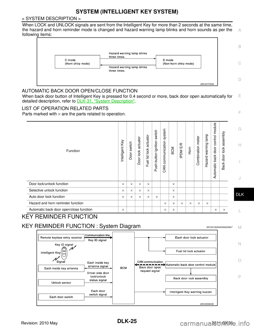
When LOCK and UNLOCK signals are sent from the Intelligent Key for more than 2 seconds at the same time,
the hazard and horn reminder mode is changed and hazard warning lamp blinks and horn sounds as per the
following items:
AUTOMATIC BACK DOOR OPEN/CLOSE FUNCTION
When back door button of Intelligent Key is pressed fo r 0.4 second or more, back door open automatically for
detailed description, refer to DLK-31, "
System Description".
LIST OF OPERATION RELATED PARTS
Parts marked with × are the parts related to operation.
KEY REMINDER FUNCTION
KEY REMINDER FUNCTION : System DiagramINFOID:0000000006225847
JMKIA2755GB
Function
Intelligent Key
Door switch
Door lock actuator
Fuel lid lock actuator
Push-button ignition switch
CAN communication system BCM
IPDM E/R
Horn
Combination meter
Hazard warning lamp
Automatic back door control module
Back door lock assembly
Door lock/unlock function ×××× ×
Selective unlock function ×××× ×
Auto door lock function ××××× ×
Hazard and horn reminder function ××××××
Automatic back door open/close function ×××××
JMKIA5084GB
Revision: 2010 May2011 QX56
Page 1562 of 5598
DLK-26
< SYSTEM DESCRIPTION >
SYSTEM (INTELLIGENT KEY SYSTEM)
KEY REMINDER FUNCTION : System Description
INFOID:0000000006225848
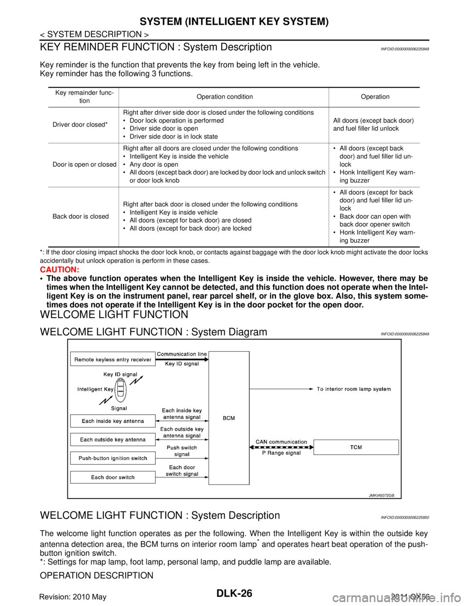
Key reminder is the function that prevents the key from being left in the vehicle.
Key reminder has the following 3 functions.
*: If the door closing impact shocks the door lock knob, or contacts against baggage with the door lock knob might activate the door locks
accidentally but unlock operation is perform in these cases.
CAUTION:
The above function operates when the Intelligent Key is inside the vehicle. However, there may be
times when the Intelligent Key cannot be detected, and this function does not operate when the Intel-
ligent Key is on the instrument panel, rear parcel shelf, or in the glove box. Also, this system some-
times does not operate if the Intelligent Key is in the door pocket for the open door.
WELCOME LIGHT FUNCTION
WELCOME LIGHT FUNCTION : System DiagramINFOID:0000000006225849
WELCOME LIGHT FUNCTION : System DescriptionINFOID:0000000006225850
The welcome light function operates as per the following. When the Intelligent Key is within the outside key
antenna detection area, the BCM turns on interior room lamp
* and operates heart beat operation of the push-
button ignition switch.
*: Settings for map lamp, foot lamp, personal lamp, and puddle lamp are available.
OPERATION DESCRIPTION
Key remainder func-
tion Operation condition Operation
Driver door closed* Right after driver side door is closed under the following conditions
Door lock operation is performed
Driver side door is open
Driver side door is in lock state All doors (except back door)
and fuel filler lid unlock
Door is open or closed Right after all doors are closed under the following conditions
Intelligent Key is inside the vehicle
Any door is open
All doors (except back door) are locked by door lock and unlock switch
or door lock knob All doors (except back
door) and fuel filler lid un-
lock
Honk Intelligent Key warn- ing buzzer
Back door is closed Right after back door is closed under the following conditions
Intelligent Key is inside vehicle
All doors (except for back door) are closed
All doors (except for back door) are locked All doors (except for back
door) and fuel filler lid un-
lock
Back door can open with back door opener switch
Honk Intelligent Key warn-
ing buzzer
JMKIA5072GB
Revision: 2010 May2011 QX56
Page 1659 of 5598
DOOR LOCK ACTUATORDLK-123
< DTC/CIRCUIT DIAGNOSIS >
C
DE
F
G H
I
J
L
M A
B
DLK
N
O P
DOOR LOCK ACTUATOR
DRIVER SIDE
DRIVER SIDE : Comp onent Function CheckINFOID:0000000006225931
1.CHECK FUNCTION
1. Select “DOOR LOCK” of “BCM” using CONSULT-III.
2. Select “DOOR LOCK” in “ACTIVE TEST” mode.
3. Touch “ALL LOCK” or “ALL UNLK” to check that it works normally.
Is the inspection result normal?
YES >> Door lock actuator is OK.
NO >> Refer to DLK-123, "
DRIVER SIDE : Diagnosis Procedure".
DRIVER SIDE : Diag nosis ProcedureINFOID:0000000006225932
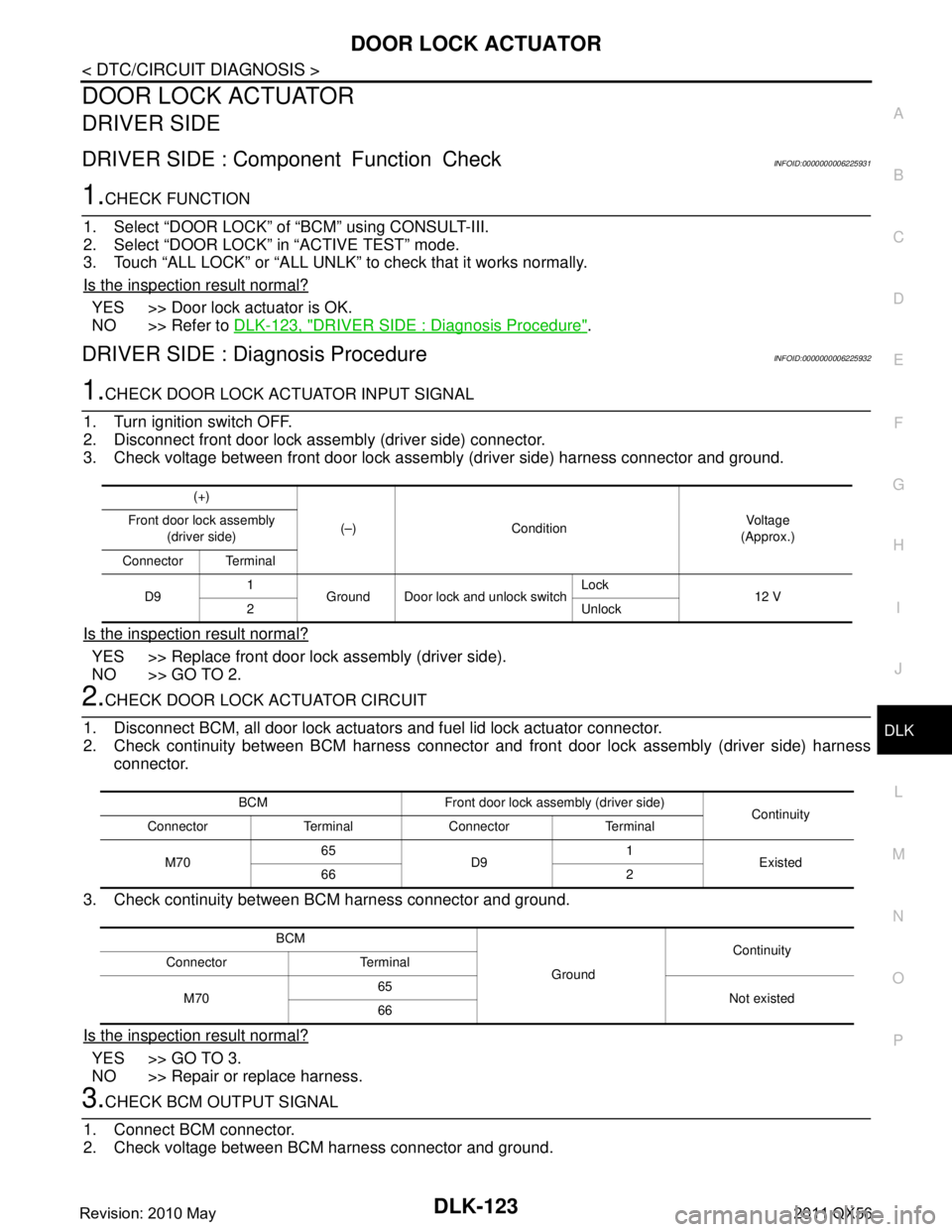
1.CHECK DOOR LOCK ACTUATOR INPUT SIGNAL
1. Turn ignition switch OFF.
2. Disconnect front door lock assembly (driver side) connector.
3. Check voltage between front door lock assembly (driver side) harness connector and ground.
Is the inspection result normal?
YES >> Replace front door lock assembly (driver side).
NO >> GO TO 2.
2.CHECK DOOR LOCK ACTUATOR CIRCUIT
1. Disconnect BCM, all door lock actuator s and fuel lid lock actuator connector.
2. Check continuity between BCM harness connector and front door lock assembly (driver side) harness
connector.
3. Check continuity between BCM harness connector and ground.
Is the inspection result normal?
YES >> GO TO 3.
NO >> Repair or replace harness.
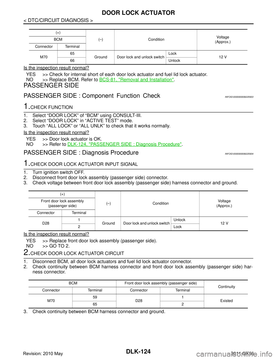
3.CHECK BCM OUTPUT SIGNAL
1. Connect BCM connector.
2. Check voltage between BCM harness connector and ground.
(+)
(–) Condition Vo l ta g e
(Approx.)
Front door lock assembly
(driver side)
Connector Terminal
D9 1
Ground Door lock and unlock switch Lock
12 V
2 Unlock
BCM Front door lock assembly (driver side) Continuity
Connector Terminal Connector Terminal
M70 65
D9 1
Existed
66 2
BCM GroundContinuity
Connector Terminal
M70 65
Not existed
66
Revision: 2010 May2011 QX56
Page 1660 of 5598
DLK-124
< DTC/CIRCUIT DIAGNOSIS >
DOOR LOCK ACTUATOR
Is the inspection result normal?
YES >> Check for internal short of each door lock actuator and fuel lid lock actuator.
NO >> Replace BCM. Refer to BCS-81, "
Removal and Installation".
PASSENGER SIDE
PASSENGER SIDE : Component Function CheckINFOID:0000000006225933
1.CHECK FUNCTION
1. Select “DOOR LOCK” of “BCM” using CONSULT-III.
2. Select “DOOR LOCK” in “ACTIVE TEST” mode.
3. Touch “ALL LOCK” or “ALL UNLK” to check that it works normally.
Is the inspection result normal?
YES >> Door lock actuator is OK.
NO >> Refer to DLK-124, "
PASSENGER SIDE : Diagnosis Procedure".
PASSENGER SIDE : Diagnosis ProcedureINFOID:0000000006225934
1.CHECK DOOR LOCK ACTUATOR INPUT SIGNAL
1. Turn ignition switch OFF.
2. Disconnect front door lock assembly (passenger side) connector.
3. Check voltage between front door lock assembly (passenger side) harness connector and ground.
Is the inspection result normal?
YES >> Replace front door lock assembly (passenger side).
NO >> GO TO 2.
2.CHECK DOOR LOCK ACTUATOR CIRCUIT
1. Disconnect BCM, all door lock actuators and fuel lid lock actuator connector.
2. Check continuity between BCM harness connector and front door lock assembly (passenger side) har-
ness connector.
3. Check continuity between BCM harness connector and ground.
(+) (–) Condition Vo l ta g e
(Approx.)
BCM
Connector Terminal
M70 65
Ground Door lock and unlock switch Lock
12 V
66 Unlock
(+)
(–) Condition Vol tag e
(Approx.)
Front door lock assembly
(passenger side)
Connector Terminal
D28 1
Ground Door lock and unlock switch Unlock
12 V
2Lock
BCM Front door lock assembly (passenger side) Continuity
Connector Terminal Connector Terminal
M70 59
D28 1
Existed
65 2
Revision: 2010 May2011 QX56
Page 1661 of 5598
DOOR LOCK ACTUATORDLK-125
< DTC/CIRCUIT DIAGNOSIS >
C
DE
F
G H
I
J
L
M A
B
DLK
N
O P
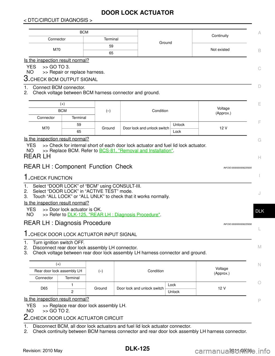
Is the inspection result normal?
YES >> GO TO 3.
NO >> Repair or replace harness.
3.CHECK BCM OUTPUT SIGNAL
1. Connect BCM connector.
2. Check voltage between BCM harness connector and ground.
Is the inspection result normal?
YES >> Check for internal short of each door lo ck actuator and fuel lid lock actuator.
NO >> Replace BCM. Refer to BCS-81, "
Removal and Installation".
REAR LH
REAR LH : Component Function CheckINFOID:0000000006225935
1.CHECK FUNCTION
1. Select “DOOR LOCK” of “BCM” using CONSULT-III.
2. Select “DOOR LOCK” in “ACTIVE TEST” mode.
3. Touch “ALL LOCK” or “ALL UNLK” to check that it works normally.
Is the inspection result normal?
YES >> Door lock actuator is OK.
NO >> Refer to DLK-125, "
REAR LH : Diagnosis Procedure".
REAR LH : Diagnosis ProcedureINFOID:0000000006225936
1.CHECK DOOR LOCK ACTUATOR INPUT SIGNAL
1. Turn ignition switch OFF.
2. Disconnect rear door lock assembly LH connector.
3. Check voltage between rear door lock assembly LH harness connector and ground.
Is the inspection result normal?
YES >> Replace rear door lock assembly LH.
NO >> GO TO 2.
2.CHECK DOOR LOCK ACTUATOR CIRCUIT
1. Disconnect BCM, all door lock actuator s and fuel lid lock actuator connector.
2. Check continuity between BCM harness connector and rear door lock assembly LH harness connector.
BCM
GroundContinuity
Connector Terminal
M70 59
Not existed
65
(+)
(–) Condition Vo l ta g e
(Approx.)
BCM
Connector Terminal
M70 59
Ground Door lock and unlock switch Unlock
12 V
65 Lock
(+)
(–) Condition Vo l ta g e
(Approx.)
Rear door lock assembly LH
Connector Terminal
D65 1
Ground Door lock and unlock switch Lock
12 V
2 Unlock
Revision: 2010 May2011 QX56
Page 1662 of 5598
DLK-126
< DTC/CIRCUIT DIAGNOSIS >
DOOR LOCK ACTUATOR
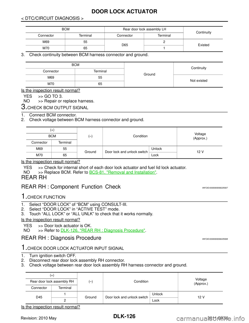
3. Check continuity between BCM harness connector and ground.
Is the inspection result normal?
YES >> GO TO 3.
NO >> Repair or replace harness.
3.CHECK BCM OUTPUT SIGNAL
1. Connect BCM connector.
2. Check voltage between BCM harness connector and ground.
Is the inspection result normal?
YES >> Check for internal short of each door lock actuator and fuel lid lock actuator.
NO >> Replace BCM. Refer to BCS-81, "
Removal and Installation".
REAR RH
REAR RH : Component Function CheckINFOID:0000000006225937
1.CHECK FUNCTION
1. Select “DOOR LOCK” of “BCM” using CONSULT-III.
2. Select “DOOR LOCK” in “ACTIVE TEST” mode.
3. Touch “ALL LOCK” or “ALL UNLK” to check that it works normally.
Is the inspection result normal?
YES >> Door lock actuator is OK.
NO >> Refer to DLK-126, "
REAR RH : Diagnosis Procedure".
REAR RH : Diagnosis ProcedureINFOID:0000000006225938
1.CHECK DOOR LOCK ACTUATOR INPUT SIGNAL
1. Turn ignition switch OFF.
2. Disconnect rear door lock assembly RH connector.
3. Check voltage between rear door lock assembly RH harness connector and ground.
Is the inspection result normal?
BCM Rear door lock assembly LH Continuity
Connector Terminal Connector Terminal
M69 55 D652
Existed
M70 65 1
BCM GroundContinuity
Connector Terminal
M69 55 Not existed
M70 65
(+)
(–) Condition Vo l ta g e
(Approx.)
BCM
Connector Terminal M69 55 Ground Door lock and unlock switch Unlock
12 V
M70 65 Lock
(+)
(–) Condition Vol tag e
(Approx.)
Rear door lock assembly RH
Connector Terminal
D45 1
Ground Door lock and unlock switch Unlock
12 V
2Lock
Revision: 2010 May2011 QX56
Page 1663 of 5598
DOOR LOCK ACTUATORDLK-127
< DTC/CIRCUIT DIAGNOSIS >
C
DE
F
G H
I
J
L
M A
B
DLK
N
O P
YES >> Replace rear door lock assembly RH.
NO >> GO TO 2.
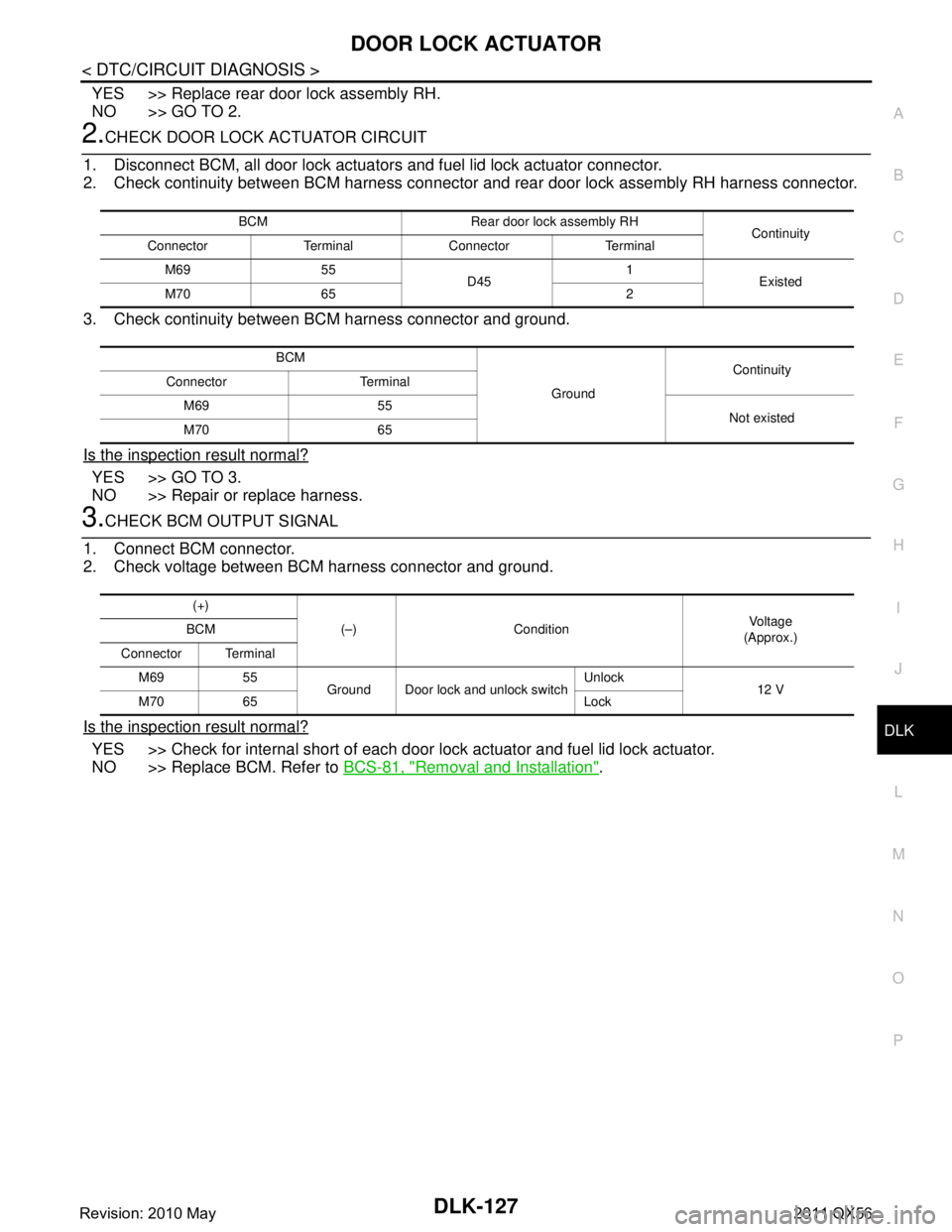
2.CHECK DOOR LOCK ACTUATOR CIRCUIT
1. Disconnect BCM, all door lock actuator s and fuel lid lock actuator connector.
2. Check continuity between BCM harness connector and rear door lock assembly RH harness connector.
3. Check continuity between BCM harness connector and ground.
Is the inspection result normal?
YES >> GO TO 3.
NO >> Repair or replace harness.
3.CHECK BCM OUTPUT SIGNAL
1. Connect BCM connector.
2. Check voltage between BCM harness connector and ground.
Is the inspection result normal?
YES >> Check for internal short of each door lo ck actuator and fuel lid lock actuator.
NO >> Replace BCM. Refer to BCS-81, "
Removal and Installation".
BCM Rear door lock assembly RH
Continuity
Connector Terminal Connector Terminal
M69 55 D451
Existed
M70 65 2
BCM GroundContinuity
Connector Terminal
M69 55 Not existed
M70 65
(+)
(–) Condition Vo l ta g e
(Approx.)
BCM
Connector Terminal M69 55 Ground Door lock and unlock switch Unlock
12 V
M70 65 Lock
Revision: 2010 May2011 QX56