Page 5049 of 5598

STC-4
< SYSTEM DESCRIPTION >
COMPONENT PARTS
SYSTEM DESCRIPTION
COMPONENT PARTS
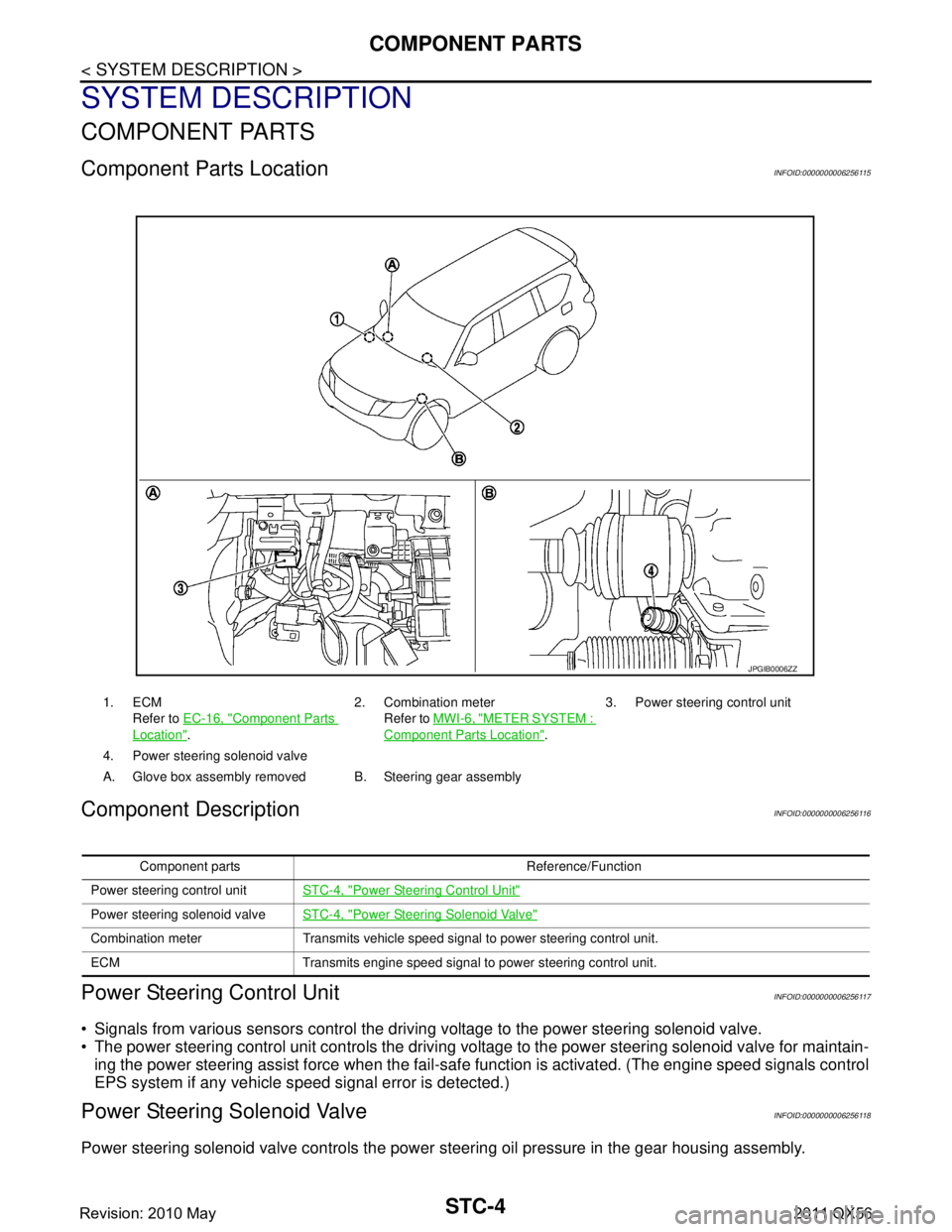
Component Parts LocationINFOID:0000000006256115
Component DescriptionINFOID:0000000006256116
Power Steering Control UnitINFOID:0000000006256117
Signals from various sensors control the driving voltage to the power steering solenoid valve.
The power steering control unit controls the driving vo ltage to the power steering solenoid valve for maintain-
ing the power steering assist force when the fail-safe function is activated. (The engine speed signals control
EPS system if any vehicle s peed signal error is detected.)
Power Steering Solenoid ValveINFOID:0000000006256118
Power steering solenoid valve controls the power steering oil pressure in the gear housing assembly.
1. ECM
Refer to EC-16, "
Component Parts
Location". 2. Combination meter
Refer to MWI-6, "
METER SYSTEM :
Component Parts Location". 3. Power steering control unit
4. Power steering solenoid valve
A. Glove box assembly removed B. Steering gear assembly
JPGIB0006ZZ
Component parts Reference/Function
Power steering control unit STC-4, "
Power Steering Control Unit"
Power steering solenoid valveSTC-4, "Power Steering Solenoid Valve"
Combination meter Transmits vehicle speed signal to power steering control unit.
ECM Transmits engine speed signal to power steering control unit.
Revision: 2010 May2011 QX56
Page 5403 of 5598
IN-CABIN MICROFILTERVTL-17
< REMOVAL AND INSTALLATION >
C
DE
F
G H
J
K L
M A
B
VTL
N
O P
IN-CABIN MICROFILTER
Exploded ViewINFOID:0000000006276313
Refer to VTL-14, "Exploded View".
Removal and InstallationINFOID:0000000006276314
REMOVAL
1. Remove glove box assembly. Refer to IP-14, "Removal and Installation".
2. Remove filter cover, and then remove air conditioner filter.
CAUTION:
If the filter is deformed/damaged when removing , replace it with a new one. Deformed/damaged filter
may deteriorate the dust collecting performance.
INSTALLATION
Note the following item, and install in the reverse order of removal.
CAUTION:
When installing, handle the filter with ext reme care to avoid deforming/damaging.
ReplacementINFOID:0000000006276315
Replace in-cabin microfilter.
Refer to MA-6, "
Schedule 1" and MA-8, "Schedule 2".
Affix a caution label inside the glove box when replacing filter.
Revision: 2010 May2011 QX56
Page 5456 of 5598
WT-6
< SYSTEM DESCRIPTION >
COMPONENT PARTS
SYSTEM DESCRIPTION
COMPONENT PARTS
Component Parts LocationINFOID:0000000006225488
1. BCMRefer to BCS-4, "
BODY CONTROL
SYSTEM : Component Parts Loca-
tion". 2. AV control unit
Refer to AV- 9 , "
Component Parts Lo-
cation". 3. ABS actuator and electric unit (con-
trol unit)
Refer to BRC-10, "Component Parts
Location".
4. TCM
*
Refer to TM-10, "A/T CONTROL SYS-
TEM : Component Parts Location" .5. Low tire pressure warning control
unit 6. Transmitter
7. Front tire pressure receiver 8. Rear tire pressure receiver
A. Glove box assembly removed B. Wheel C. Fender protector (rear side)
D. Low tire pressure warning lamp (in
combination meter) E. Inside rear wheel house protector
*: Mainly used for the tire inflation indicator function.
JPEIC0069ZZ
Revision: 2010 May2011 QX56
Page 5515 of 5598
LOW TIRE PRESSURE WARNING CONTROL UNIT
WT-65
< REMOVAL AND INSTALLATION >
C
D F
G H
I
J
K L
M A
B
WT
N
O P
LOW TIRE PRESSURE WA RNING CONTROL UNIT
Exploded ViewINFOID:0000000006225550
Removal and InstallationINFOID:0000000006225551
REMOVAL
1. Remove the glove box assembly. Refer to IP-14, "Removal and Installation".
2. Remove the instrument lower panel RH. Refer to IP-14, "
Removal and Installation".
3. Disconnect low tire pressure warning control unit connector.
4. Remove the low tire pressure warning control unit control unit.
INSTALLATION
Note the following, install in the reverse order of removal.
Perform ID registration after replacing low tire pressure warning control unit. Refer to WT-29, "
Work Proce-
dure".
1. Low tire pressure warning control unit 2. Bracket
: Vehicle front
Refer to GI-4, "
Components" for symbols in the figure.
JPEIC0072ZZ
Revision: 2010 May2011 QX56
Page:
< prev 1-8 9-16 17-24